In modern structural engineering, truss systems serve as the backbone of long-span architecture. Among the various configurations, the N-Truss—characterized by parallel top and bottom chords and diagonally arranged web members—remains a cornerstone of efficiency and stability. Originally designed to simplify load transfer and minimize material usage, the N-Truss (also known as the Pratt truss) continues to play a pivotal role in contemporary steel construction, from factory roofs to railway bridges. Its systematic geometry allows engineers to achieve maximum strength with minimal weight, representing an ideal balance between design simplicity and structural reliability.
1. Understanding the N-Truss System
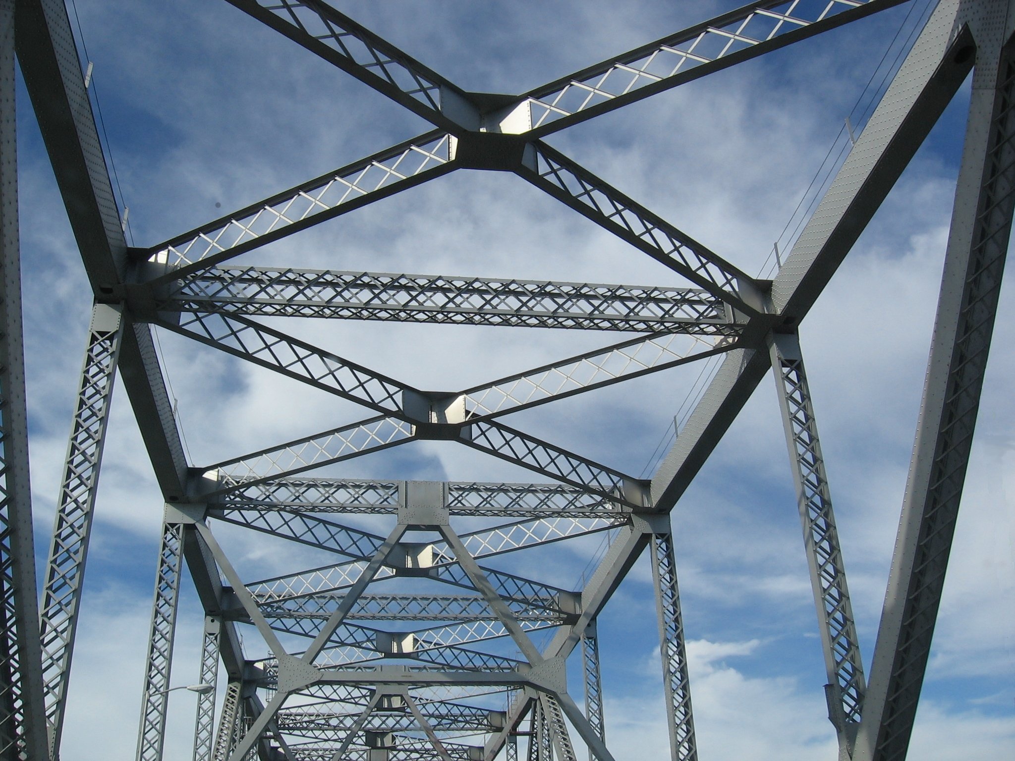
1.1 Definition and Geometry
An N-Truss is a triangulated framework consisting of two parallel chords—the upper chord under compression and the lower chord under tension—connected by vertical and diagonal web members. The diagonals are typically in tension while the verticals resist compression. The resulting pattern resembles a series of capital “N” letters repeated along the span. This geometry efficiently channels loads to the supports and ensures stability even under dynamic conditions.
1.2 Historical Background
The N-Truss concept originated in the 1840s through the pioneering work of Thomas and Caleb Pratt, whose Pratt truss design revolutionized bridge engineering. Its configuration minimized the need for heavy compression diagonals, enabling the use of slender tension members that reduced overall weight. The system quickly became the preferred choice for railway and highway bridges across Europe and North America. Over time, advancements in steel fabrication transformed the traditional timber-and-iron Pratt truss into the all-steel N-Truss used today in factories, warehouses, and public infrastructure.
1.3 Engineering Significance
Engineers favor the N-Truss due to its predictable load behavior, economy of materials, and modular adaptability. The parallel chords simplify detailing, while the repetitive geometry allows prefabrication in standard units. Whether used for industrial roofs or pedestrian bridges, the N-Truss ensures structural integrity with reduced deflection and optimal stiffness-to-weight ratio.
2. Structural Behavior and Load Distribution
2.1 How Loads Are Transferred
In an N-Truss structure, vertical loads from the roof deck or bridge deck are transmitted first to the top chord, then distributed through the web members to the bottom chord and finally to the supports. Diagonal members primarily carry tensile forces, while verticals handle compression. The result is an even distribution of stress that minimizes bending moments in the chords and improves efficiency under live and dead loads.
2.2 Key Parameters in Design
| Parameter | Description | Typical Range/Value |
|---|---|---|
| Span Length | Distance between supports | 20–80 m (roof), 30–120 m (bridge) |
| Depth-to-Span Ratio | Determines stiffness and economy | 1:10 to 1:15 |
| Chord Member Type | Main load-carrying elements | H-section, box, or tubular |
| Web Member Type | Tension/Compression members | Angle or round bar |
| Connection Type | Joins members at nodes | Bolted or welded with gusset plates |
2.3 Advantages of the N-Truss Configuration
- Lightweight structure with excellent stiffness.
- Efficient material utilization with minimal waste.
- Easy to prefabricate and assemble on site.
- Superior load-carrying performance for long spans.
- Good resistance to vertical and moderate lateral loads.
3. Design Considerations for Steel N-Truss Structures
Designing a reliable and efficient N-Truss structure requires a comprehensive understanding of materials, load behavior, design codes, and connection detailing. Each of these factors directly influences the truss’s overall stability, durability, and economic feasibility. An optimized design balances safety, material efficiency, and constructability, ensuring that the system performs predictably under both static and dynamic conditions. The following subsections outline the main design considerations essential for successful implementation of an N-Truss in steel structure projects.
3.1 Material Selection
The performance of any N-Truss system is closely tied to the properties of its materials. Structural steel is the preferred choice due to its high strength-to-weight ratio, uniform quality, and ductile behavior under load. Modern high-strength, low-alloy steels—such as Q355B, S355JR, ASTM A572, and SM490A—offer superior tensile strength while maintaining excellent weldability and toughness, even at low temperatures.
When selecting materials, engineers must consider both mechanical and environmental factors. Mechanical requirements include yield strength, ultimate tensile strength, elongation, and impact resistance, while environmental considerations cover corrosion exposure, temperature variations, and humidity levels. For projects in coastal or industrial zones, enhanced corrosion protection is critical. Common surface treatments include:
- Hot-Dip Galvanizing: Immersing steel in molten zinc provides a metallurgical bond, forming a long-lasting corrosion-resistant coating suitable for marine or outdoor conditions.
- Epoxy Coating: A thick protective barrier that offers excellent resistance to moisture, salt, and chemical exposure.
- Zinc-Rich Primers: Applied as a base coat in multi-layer painting systems, these primers provide cathodic protection to steel surfaces.
In certain designs, composite materials or hybrid systems may be introduced to improve performance. For example, combining steel with reinforced concrete or fiber-reinforced polymer (FRP) components can enhance durability and stiffness while reducing overall weight. Ultimately, the material choice must align with structural demands, lifecycle expectations, and maintenance strategies.
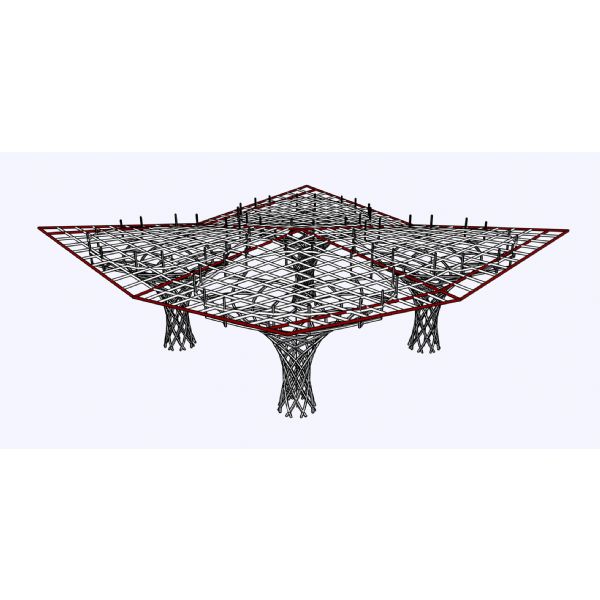
3.2 Structural Analysis and Modelling
The analysis of an N-Truss involves evaluating its response to various load conditions and ensuring that each member operates within its safe stress limits. Designers employ both traditional analytical methods and advanced computational modeling to assess behavior accurately.
Manual calculations based on the method of joints or method of sections remain essential for conceptual design and validation. However, for complex geometries and long spans, engineers rely on Finite Element Analysis (FEA) software such as ANSYS, SAP2000, or STAAD.Pro to model three-dimensional behavior. FEA allows precise simulation of:
- Axial forces and bending moments in truss members.
- Deflection and deformation under different load cases.
- Vibration and dynamic responses for bridges and cranes.
- Stress concentrations near connections and gusset plates.
Accurate modeling requires defining realistic load combinations according to international standards. Common load categories include:
- Dead Load (DL): The self-weight of the truss, roof cladding, purlins, and permanent fixtures.
- Live Load (LL): Loads from occupancy, maintenance activities, or movable objects.
- Wind Load (WL): Horizontal and uplift pressures as per local wind codes.
- Seismic Load (EQ): Horizontal and vertical forces induced by ground motion.
- Temperature and Shrinkage Effects: Differential expansion or contraction of steel components.
To ensure safety and economy, each member’s slenderness ratio, buckling length, and allowable stress must be carefully checked. Optimization studies may also be conducted to minimize weight while satisfying all strength and serviceability requirements.
3.3 Design Standards and Codes
Adherence to recognized design codes ensures that an N-Truss meets structural integrity and safety expectations. Different regions apply specific standards, each providing detailed rules for member sizing, load factors, and connection design. The most widely used standards include:
- Eurocode 3 (EN 1993): Comprehensive guidance on the design of steel structures, covering both ultimate and serviceability limit states. It emphasizes load combinations, stability analysis, and member classification based on cross-sectional behavior.
- AISC 360 (U.S.): Provides design and construction criteria for structural steel buildings using both Allowable Strength Design (ASD) and Load and Resistance Factor Design (LRFD) methods.
- GB50017 (China): National standard for steel structure design, incorporating load reduction factors and resistance checks tailored for regional seismic and wind conditions.
These codes define critical performance requirements, including:
- Allowable stresses and load factors.
- Deflection limits to control serviceability (typically span/240 for roof trusses).
- Stability verification for compression and tension members.
- Fatigue analysis for members subjected to cyclic loads, such as in bridges or cranes.
Following these standards ensures uniformity in design methodology, facilitates peer review, and simplifies approval by local authorities. In international projects, engineers often perform comparative checks between codes to align safety margins and material grades.
3.4 Connection Design
In an N-Truss, connections are the most critical elements affecting performance and constructability. Even if individual members are perfectly designed, poor connection detailing can compromise overall stability. Connections serve to transmit axial forces between chords and web members while maintaining geometric accuracy under load.
The two primary types of truss connections are welded and bolted. Welded connections are typically used in shop fabrication, offering high strength and rigidity, while bolted joints provide flexibility for on-site assembly and maintenance. Each connection must be designed to handle both tension and compression forces without causing eccentric stress concentrations.
The connection layout typically includes gusset plates—flat steel plates used to join members at a node. Proper gusset plate design considers the following parameters:
- Thickness sufficient to resist shear and bending forces.
- Adequate edge and end distances for bolt placement.
- Hole spacing and diameter compliant with code specifications.
- Avoidance of overlapping welds or bolt interference between members.
In bridges or dynamic structures, fatigue resistance is a key concern. Engineers analyze stress ranges and apply detail category classifications to ensure connections remain crack-free over millions of load cycles. Techniques such as full-penetration groove welds, double-shear connections, and pre-tensioned high-strength bolts (Grade 10.9 or ASTM A490) are commonly applied to enhance fatigue life.
Another important aspect is constructability. Connections must be designed for easy alignment during erection, minimizing the need for field adjustments. Use of standardized bolt-hole patterns and modular connection kits can accelerate installation and reduce errors. All connections are subject to strict inspection procedures, including visual checks, magnetic particle testing, and ultrasonic testing for weld integrity.
Ultimately, a well-designed connection system transforms the N-Truss into a continuous, integrated framework capable of carrying large loads efficiently and safely throughout its service life.
4. Architectural and Functional Applications
The N-Truss is not merely a structural component but a versatile system that integrates function, form, and efficiency across diverse architectural and engineering domains. Its modular geometry, lightweight configuration, and clear load paths make it suitable for a wide range of structures—from industrial complexes and bridges to public buildings and aesthetic architectural forms. The following sections examine its principal areas of application.
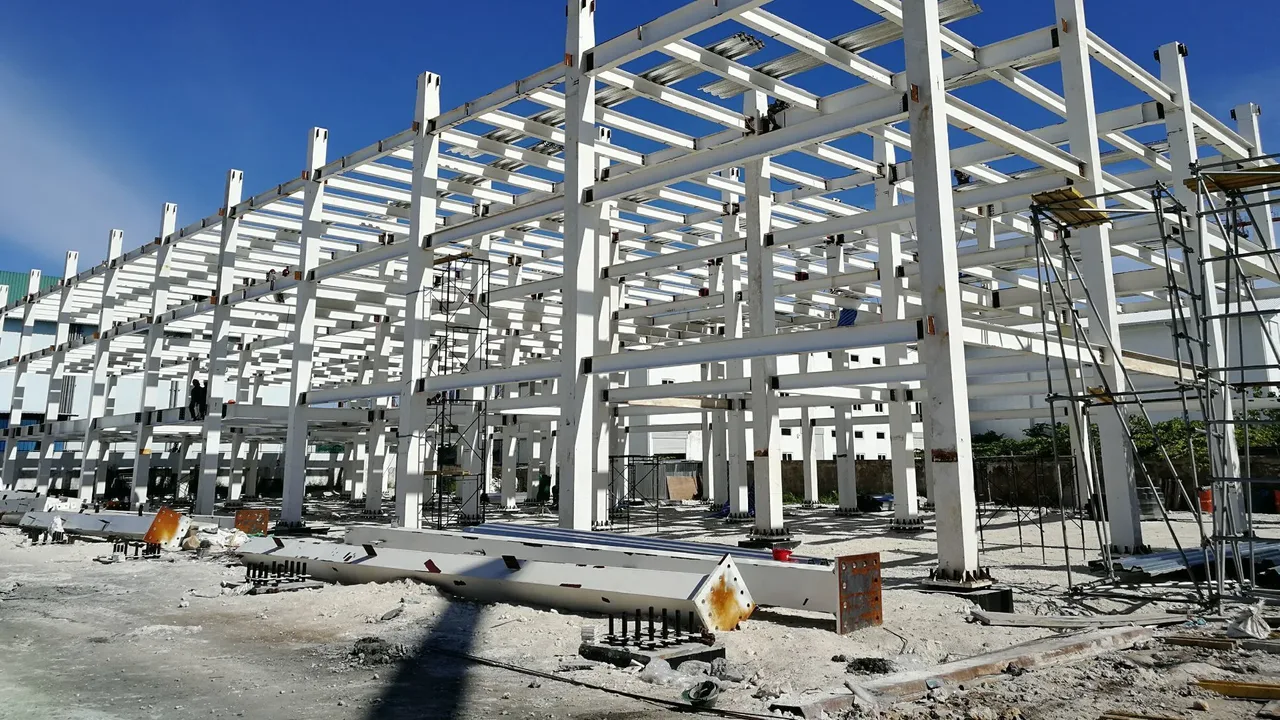
4.1 Industrial and Commercial Buildings
In industrial and commercial construction, the N-Truss stands out for its ability to provide large, unobstructed interior spaces with minimal material consumption. These open spaces are essential in facilities such as manufacturing plants, logistics warehouses, aircraft hangars, and assembly halls where uninterrupted floor area is critical for equipment movement, production lines, and storage efficiency.
The symmetrical pattern of the N-Truss allows for uniform load distribution and reduces bending moments in beams and columns. Its repetitive geometry simplifies both design and construction, allowing for standardized fabrication and rapid on-site assembly. Additionally, the system can easily accommodate overhead cranes, HVAC ducts, skylights, and photovoltaic panels without significant modifications to the structure.
Another important advantage is flexibility of roof design. Engineers can adapt the truss spacing, height, and chord thickness to meet varying load demands and architectural styles. For example, low-slope trusses are ideal for logistics centers, while high-pitched configurations enhance ventilation and daylighting in manufacturing buildings.
Energy efficiency also plays a role in modern N-Truss building designs. By integrating insulation panels and reflective roof coatings, steel truss structures can maintain interior temperature stability and reduce operational energy costs. The combination of prefabrication and modularity ensures consistent quality while minimizing construction waste—an important factor in green building certification.
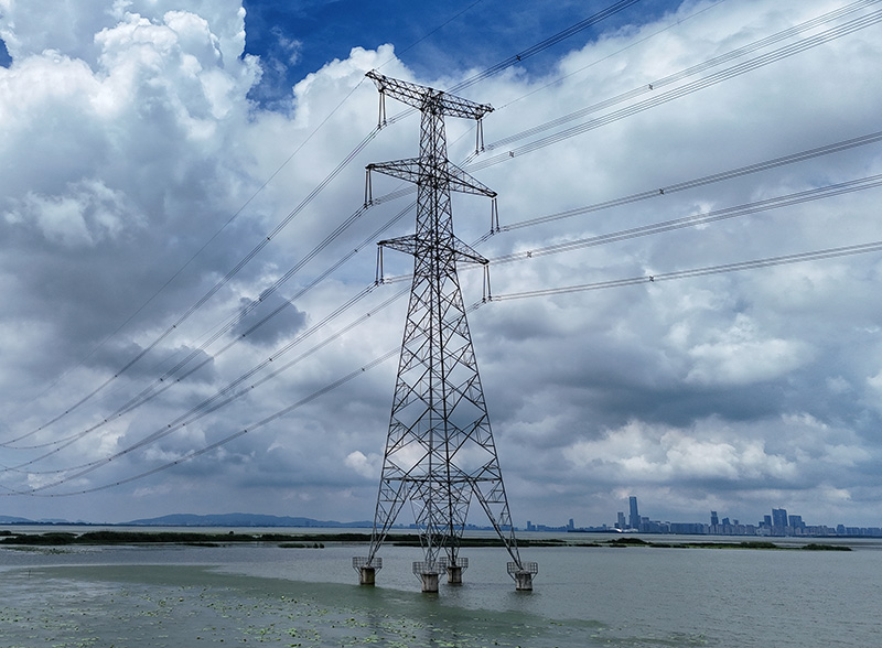
4.2 Bridges and Infrastructure
The N-Truss has long been a staple in bridge engineering, where it provides a balance between weight, strength, and constructability. Commonly referred to as a Pratt truss bridge in traditional terminology, this configuration efficiently manages the alternating compression and tension forces generated by moving loads such as trains, trucks, and pedestrians.
Steel truss bridges built with the N-Truss arrangement can span anywhere from 30 to 120 meters, depending on the material strength and truss depth. The design’s linear load transfer ensures that stress concentrations remain low, minimizing fatigue and extending service life. Moreover, prefabricated truss panels allow for modular construction—segments can be assembled on-site and joined using high-strength bolts or welded splices, accelerating project timelines.
Compared with other truss types like the Warren or Howe, the N-Truss offers superior performance under variable live loads because the diagonal tension members efficiently resist dynamic forces. This makes it ideal for applications such as railway bridges, pedestrian overpasses, and vehicular crossings where continuous load variation occurs.
Additionally, its open web configuration reduces wind resistance and material consumption, improving aerodynamic performance and cost-effectiveness. Regular inspection access is also simplified by the predictable geometry, allowing maintenance crews to reach key joints and gusset plates with ease.
4.3 Architectural Aesthetics
While the N-Truss is rooted in engineering functionality, it has increasingly become a design statement in modern architecture. Its rhythmic triangulation and visual transparency communicate both structural integrity and artistic precision. Architects often expose trusses in public spaces—such as airports, sports arenas, exhibition centers, and terminals—to celebrate the beauty of structural honesty.
Exposed N-Trusses can be finished with high-performance coatings, polished metal finishes, or integrated lighting systems to enhance the architectural expression. When combined with glass, aluminum, or membrane roofs, they create a striking visual rhythm that emphasizes both depth and openness. In interior spaces, trusses can even serve as support systems for catwalks, lighting rigs, and acoustic panels.
The combination of structural logic and aesthetic appeal positions the N-Truss as a symbol of industrial modernism—where strength, efficiency, and elegance coexist harmoniously.
5. From Design to Fabrication
The journey from conceptual design to fabrication is a critical phase in the lifecycle of any N-Truss project. Precision, coordination, and adherence to quality standards ensure that each truss component functions exactly as intended. The process involves several key steps—from technical detailing to workshop fabrication and surface treatment.
5.1 Detailing and Shop Drawings
Detailing is the foundation of truss fabrication accuracy. Engineers produce comprehensive shop drawings that define every aspect of the structure—member identification, geometry, material specifications, bolt grades, and welding symbols. These drawings serve as the blueprint for manufacturing and assembly.
Advanced Building Information Modeling (BIM) tools are employed to generate 3D models that integrate structural, mechanical, and architectural systems. BIM coordination ensures that ducts, piping, and electrical conduits do not clash with truss members. It also allows automatic generation of bills of materials and cutting lists, improving workflow efficiency.
Tolerance management is another critical component. Each joint and member must be dimensionally consistent with the 3D model to ensure seamless assembly on site. Dimensional deviations beyond ±2 mm in key nodes can result in misalignment or load imbalance, emphasizing the importance of digital precision in modern fabrication workflows.
5.2 Cutting, Welding, and Assembly
The fabrication process begins with CNC-based cutting machines that achieve high accuracy and smooth edges, minimizing material waste. After cutting, members are assembled into subframes using jigs and fixtures to maintain geometry. Welding follows approved procedures in compliance with AWS D1.1 or ISO 3834 standards, depending on the project location.
Non-destructive testing (NDT), such as ultrasonic testing (UT) and magnetic particle inspection (MPI), ensures weld integrity and detects hidden flaws before assembly proceeds. Once welding and inspection are complete, a trial assembly is often conducted within the workshop. This step verifies that bolt holes align correctly and that the truss geometry conforms to the design before the structure is disassembled for shipping.
5.3 Surface Treatment and Coating
To protect against environmental degradation, fabricated components undergo surface cleaning via shot blasting to achieve a Sa 2.5 cleanliness level. Following this, a multi-layer coating system is applied:
- Primer Coat: Zinc-rich epoxy providing corrosion protection.
- Intermediate Coat: High-build epoxy for mechanical durability.
- Top Coat: Polyurethane or fluorocarbon for UV and weather resistance.
In high-humidity or coastal regions, hot-dip galvanizing or duplex systems (galvanizing + paint) are preferred to achieve service lifespans exceeding 30 years with minimal maintenance. Each coating layer is verified for thickness and adhesion through standardized testing procedures.
6. Transportation and On-Site Installation
After fabrication, the next challenge lies in safely transporting and erecting the N-Truss on site. Proper logistics, handling, and sequencing are vital to maintain precision and avoid structural damage during this phase.
6.1 Logistics and Handling
Given the large dimensions of truss segments, transportation is typically modularized. Each segment is fabricated to fit within the transport constraints (commonly less than 12 meters in length for road shipping). Special lifting points are designated in the shop drawings to ensure safe crane handling during loading and unloading.
Temporary stiffeners and bracings may be attached to prevent warping or torsional deformation. During shipping, truss segments are securely fastened using padded supports and tie-downs to minimize vibration and impact damage. The logistics team must coordinate with local authorities for oversized load permits and transport escorts where necessary.
6.2 Site Preparation
Before erection begins, the foundation and anchor bolts must be thoroughly checked for position, level, and alignment. Any deviation at this stage can lead to assembly difficulties later. Surveying equipment such as total stations or laser scanners is used to ensure millimeter accuracy. Temporary scaffolding, lifting equipment, and rigging systems are then installed to facilitate a safe working environment.
6.3 Erection Methods
Erection of N-Truss structures follows a planned sequence designed to maintain stability throughout construction. For smaller trusses, members are assembled in place using cranes to lift components one by one. For larger spans, the entire truss may be pre-assembled on the ground and lifted in a single operation—a technique known as the “mega-lift” method. This approach significantly reduces the duration of high-elevation work and minimizes safety risks.
All on-site connections are inspected during assembly. Bolted joints are tightened to the specified torque, and welded joints undergo visual and NDT inspections before approval. Temporary supports are only removed after structural stability has been verified.
6.4 Safety and Quality Control
Safety during erection is paramount. All lifting operations follow certified rigging plans, and site workers must be equipped with appropriate PPE. Compliance with international standards such as ISO 45001 and local occupational safety laws ensures proper risk management. Documentation including inspection checklists, load certificates, and alignment reports must be maintained for each truss section.
Quality assurance personnel perform dimensional checks, coating inspections, and bolt-tightness verifications. Only after full compliance with the project quality plan is the truss structure released for final acceptance.
7. Performance Evaluation and Maintenance
Once the N-Truss structure is erected, its long-term reliability depends on systematic performance evaluation and ongoing maintenance. Monitoring ensures that the truss continues to function as designed throughout its service life.
7.1 Load Testing and Commissioning
Upon completion, engineers conduct load testing to confirm that the truss behaves according to design predictions. Controlled loads, often using water tanks or calibrated weights, are applied to simulate service conditions. Deflections and stresses are measured with strain gauges or laser displacement sensors and compared to theoretical values. Any discrepancies are analyzed and corrected before final commissioning.
For critical infrastructure like bridges or airport terminals, structural health monitoring systems (SHM) are installed. These sensors continuously record parameters such as strain, vibration, and temperature, allowing engineers to detect potential issues early and plan preventive maintenance.
7.2 Maintenance and Inspection Routine
Regular inspection is vital for ensuring the durability of N-Truss systems. Maintenance programs should include:
- Visual inspection of welds, bolts, and coatings for corrosion or fatigue cracks.
- Cleaning of debris and drainage channels to prevent moisture accumulation.
- Re-coating or touch-up painting of damaged surfaces to restore corrosion resistance.
Detailed inspections every 3–5 years may involve non-destructive testing such as ultrasonic or magnetic particle methods, particularly at high-stress nodes and gusset plates. Keeping accurate maintenance records enables trend analysis of structural performance over time.
7.3 Service Life and Sustainability
A well-designed and maintained steel N-Truss can achieve a service life exceeding 50 years. The recyclability of steel makes it one of the most sustainable construction materials available. At the end of its lifecycle, truss components can be dismantled, reused, or fully recycled without loss of material integrity.
The system’s lightweight nature also contributes to sustainability by reducing foundation mass and embodied carbon. Combined with energy-efficient coatings and modular fabrication, N-Truss structures align perfectly with global green building initiatives such as LEED and BREEAM.
Ultimately, the N-Truss represents more than a structural form—it embodies an engineering philosophy of efficiency, adaptability, and longevity that continues to shape the future of modern steel construction.
8. Case Study Example: Industrial Warehouse Roof System
To illustrate practical implementation, consider an industrial warehouse project employing an N-Truss roof system.
| Parameter | Details |
|---|---|
| Project Location | Batam, Indonesia |
| Span Length | 40 meters |
| Steel Usage | 280 tons of Q355B steel |
| Structural System | N-Truss roof supported by rigid portal frames |
| Completion Time | 8 months from design to commissioning |
| Performance Outcome | Material savings of 15% and 25% faster installation compared to standard frames |
The project demonstrated that using prefabricated N-Truss modules can significantly enhance efficiency without compromising safety or structural performance. The lightweight configuration reduced crane requirements and allowed faster roof enclosure under tropical conditions.
9. Emerging Innovations and Future Trends
9.1 Integration with Digital Design Tools
Building Information Modeling (BIM) and parametric design are transforming how engineers approach truss geometry. Digital twins allow real-time analysis and optimization of each member for weight and cost reduction. Artificial intelligence algorithms can propose optimal configurations based on load patterns and fabrication constraints.
9.2 Advanced Materials
New steel alloys and hybrid materials enhance the traditional N-Truss. High-strength steels (up to 700 MPa yield strength) permit longer spans with smaller sections. Composite systems combining steel with concrete or FRP panels further improve stiffness and durability while maintaining lightweight characteristics.
9.3 Modular and Prefabricated Systems
Prefabrication and modular assembly continue to shape the future of N-Truss applications. Factory-produced modules ensure quality consistency, reduce on-site labor, and support rapid deployment for emergency or remote construction. The approach aligns with global trends toward sustainable, lean, and industrialized building methods.
Conclusion
From its 19th-century origins to modern digital fabrication, the N-Truss remains a symbol of engineering elegance and efficiency. Its rational geometry, material economy, and proven load-bearing capacity make it indispensable in steel structure projects worldwide. When properly designed, fabricated, and maintained, the N-Truss delivers enduring performance, aesthetic appeal, and sustainability. As technology advances, this timeless structural form continues to evolve—bridging the gap between concept and construction, and setting the standard for efficient steel design in the 21st century.