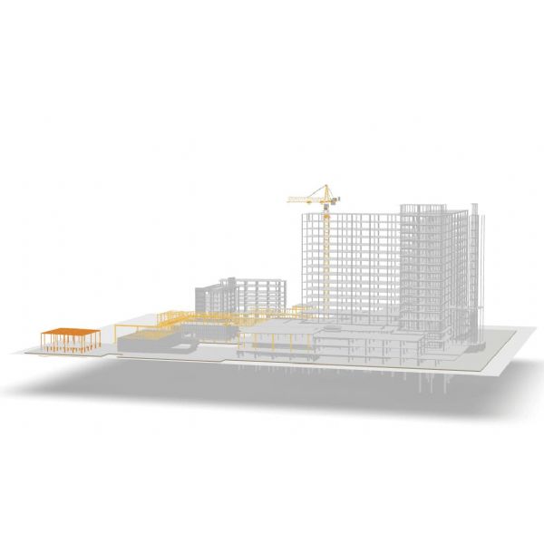

As Turkey expands its low-carbon generation capacity, the Kazan Combined Cycle Power Plant (CCPP) required grid-ready Power Transmission & Substation Facilities that could be engineered, fabricated, and erected on an aggressive schedule without compromising safety, seismic performance, or long-term maintainability. This case study presents the structural concept, engineering approach, and construction methodology behind a 845-ton truss tube steel structure package designed to support high-voltage equipment, cable routing, and control infrastructure. Completed in December 2024, the scope delivers a robust, inspection-friendly steel system with clear load paths, superior torsional stiffness, and ample reserve capacity for future expansion—helping the Kazan CCPP achieve reliable, grid-compliant export of power with minimized outage risk.
Project Snapshot
| Location | Turkey (Kazan district) |
|---|---|
| Plant Type | Combined Cycle Power Plant (CCPP) |
| Scope | Power Transmission & Substation Facilities (steel superstructures, gantries, equipment skids, cable bridges, control building frame) |
| Steel Usage | 845 tons (fabricated and erected) |
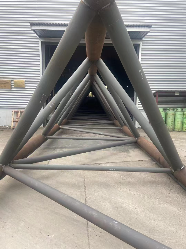
| Steel Structure Type | Truss tube steel structure (multi-bay configuration) |
| Completion | December 2024 |
Context and Objectives
The Kazan CCPP integrates high-efficiency gas turbines with heat recovery to deliver flexible baseload power. To ensure stable grid interconnection, the owner required Power Transmission & Substation Facilities with:
- High stiffness for heavy equipment support (transformers, reactors, GIS/AIS bays, bus ducts).
- Seismic and wind robustness aligned with Turkish and EN/IEC norms.
- Efficient cable management via long-span cable bridges and multi-tier trays.
- Fast erection to synchronize with commissioning windows and minimize outage risk.
- Low life-cycle cost via corrosion protection, access platforms, and replaceable components.
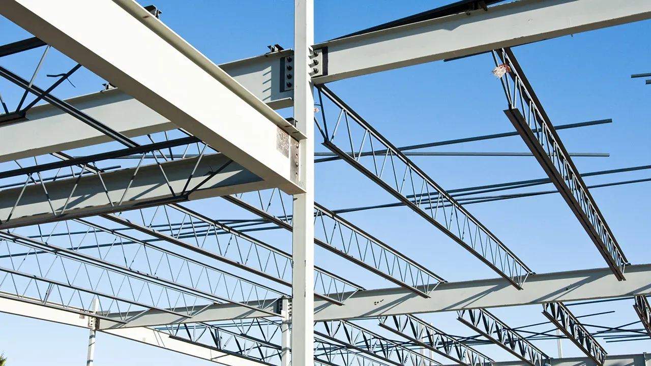
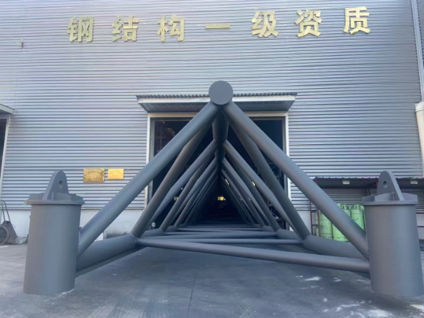
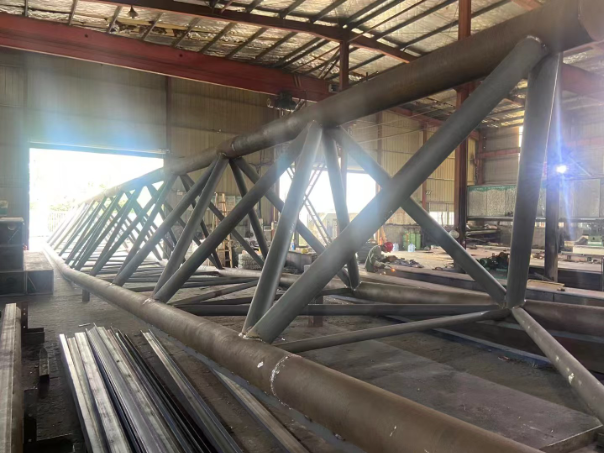
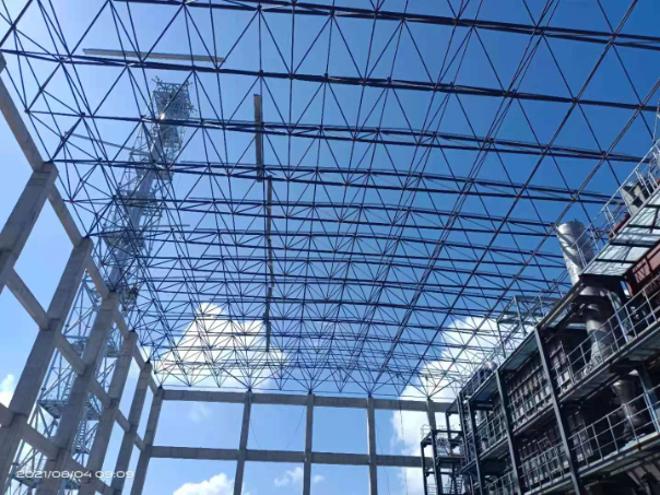
Structural Concept: Truss Tube Steel Structure
The backbone of the package is a modular truss tube steel structure system. Closed-section chords (e.g., circular or square hollow sections) combined with slender web members create a lightweight but very stiff frame, ideal for dynamic areas near transformers and bus ducts.
Why truss tube for Power Transmission & Substation Facilities ?
- Torsional stiffness & vibration control: Tubular trusses limit twist under asymmetric equipment loads and short-circuit forces.
- Long spans: Clear spans over equipment bays and cable alleys reduce foundations and interferences.
- Compact nodes: Efficient welded K- and N-joint detailing simplifies connection geometry and inspection.
- Aesthetics & maintainability: Clean lines, integrated walkways, and removable grating improve inspection and O&M access.
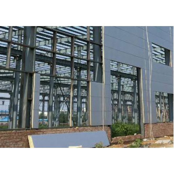
Scope of the Power Transmission & Substation Facilities
The multi-disciplinary steel scope covers the structural envelope needed to mount, protect, and access electrical equipment:
- High-Voltage Gantries & Equipment Frames: Steel gantries for incoming/outgoing lines, breaker supports, CT/VT stands, surge arrester posts, and bus duct pedestals.
- GIS/AIS Bays: Structural frames for switchgear enclosures, integrated crane beams where applicable, and embedded plates for equipment skids.
- Cable Bridges and Racks: Long-span truss walkways with multi-tier tray supports, drop-outs, and cable seal management at building penetrations.
- Control & Relay Building Frame: Steel frame for the electrical/control building, including mezzanine, equipment rooms, and HVAC platforms.
- Access & Safety: Stair towers, ladders, guardrails, kick plates, and grated platforms for safe, code-compliant access.
- Earthing & Lightning Interfaces: Steel interfaces coordinated with earthing grids and air terminals (by E&I), providing welded lugs and test points.
Design Criteria and Codes
Design aligns with relevant Turkish requirements and widely accepted EN/IEC practices for power facilities. Typical criteria include:
- Structural: EN 1990/1991 (basis & actions), EN 1993 (steel), EN 1090 (execution), with seismic and wind parameters calibrated to the site.
- Electrical Interfaces: Clearances and short-circuit loadings per project E&I specs and applicable IEC guidance for substations.
- Serviceability: Deflection limits protecting cable integrity and alignment of bus ducts and sensitive apparatus.
- Fatigue/Dynamic: Consideration of transformer vibrations and switching-induced loads on supports.
Materials, Fabrication, and Corrosion Protection
The 845-ton package uses certified structural steel grades (e.g., S355/S420 equivalents per project spec), with traceability maintained from mill certificate to installed member. Key quality controls:
- Welding: WPS/PQR qualified; welder qualifications tracked; NDT coverage per criticality (VT, MT/PT, UT where required).
- Geometry Control: Jigs for repeating nodes; camber, sweep, and twist checks prior to coating.
- Surface Prep & Coating: Sa 2.5 blast profile; duplex protection tailored to environment (e.g., hot-dip galvanizing for outdoor trusses plus topcoat system for C4–C5 conditions).
- Bolting: Pre-load bolts to class per EN 14399 where slip-critical behavior is specified; torque verification documented.
Foundations and Interfaces
Pinned baseplates on reinforced concrete pedestals minimize moment transfer and simplify leveling. Embedded anchor plans are coordinated early with civil works to ensure hold-down spacing suits truss node geometry. Interface tolerances are clearly defined between steel, switchgear skids, and cable sealing systems. Expansion joints and flexible couplings are provided at building penetrations to avoid load transfer to equipment casings.
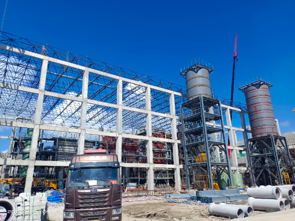
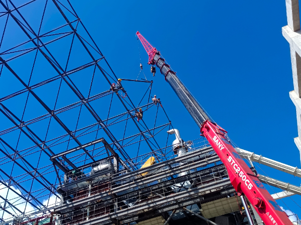
Erection Strategy and Construction Sequencing
To meet the December 2024 completion target, erection relied on modularization and parallel work fronts:
- Pre-assembly: Ground assembly of truss panels and stair modules with trial-fit of key connections.
- Lifting & Setting: Mobile cranes sized for reach around energized or restricted zones; controlled tailing for long trusses.
- Progressive Bolting & Welding: Temporary bracing to control geometry; final torqueing after plumb/line checks.
- Cable Tray Fit-out: Tray tiers installed before energized works; drop-outs verified against E&I routing.
- Punch-list & Turnover: Walkdowns by civil/steel/E&I; tagging of welds, coatings, and as-built surveys for O&M.
Safety, Access, and Maintainability
Because Power Transmission & Substation Facilities concentrate live equipment and heavy apparatus, the steel layout prioritizes safe, intuitive access:
- Access Planning: Stair towers provide vertical circulation away from high-EMF zones; grated platforms ensure drainage and grip.
- Fall Protection: Permanent lifelines and anchor points; compliant guardrails and toe boards throughout.
- Isolation & Permitting: Hot-work control, exclusion zones, and LOTO interfaces coordinated with the plant’s permit-to-work system.
- Inspection Paths: Clear 360° access to connections; removable handrails where equipment swaps are expected.
Power Transmission & Substation Facilities Cable Management and Electromagnetic Considerations
Steel cable bridges are configured to segregate power, control, and fiber, reducing interference and simplifying future adds. Longitudinal and transverse stiffness limits deflection under full cable load. Bonding lugs at intervals allow reliable earthing continuity, while cable tray supports incorporate slotted connection details to fine-tune alignment and maintain minimum bending radii.
Quality Assurance and Commissioning Support
Quality documentation covers material certificates, weld maps, NDT reports, coating DFT logs, bolt torque records, and as-built surveys. Prior to energization, joint walkdowns verify clearance envelopes, earthing continuity of steel, and free-from-snag cable routes. The steel team supports cold commissioning by providing temporary access solutions and rapid punch-list closure to keep E&I testing on track.
Sustainability and Life-Cycle Value
The truss tube scheme reduces total tonnage versus equivalent plate-girder solutions while achieving the target stiffness. Hot-dip galvanizing, compatible topcoats, and well-placed drip edges prolong coating life. Bolted splices at logical maintenance break points facilitate component replacement without full demobilization. All major members are recyclable at end-of-life, in line with the plant’s sustainability commitments.
Outcomes and Performance
- On-time completion: Steel superstructures delivered and handed over in December 2024, synchronized with plant commissioning windows.
- Operational reliability: Stiff, low-deflection support of HV apparatus and cable systems reduces maintenance interventions.
- Future-proofing: Reserve capacity and modular bays allow additional feeders or equipment to be added with minimal rework.
- Owner value: A clean, maintainable steel system that supports safe operations and consistent grid availability.
Lessons Learned
- Front-loaded coordination: Early, detailed interface control between steel and E&I reduced late-stage clashes.
- Modularization pays off: Pre-assembling truss segments and stair towers accelerated erection and improved quality.
- Access is design, not an add-on: Built-in platforms and clear inspection paths lowered O&M risk.
Recommended O&M Practices
- Annual coating inspections at connections, drip lines, and splash zones; touch-up per coating system guidelines.
- Torque sampling of critical bolted joints after major thermal cycles during the first year, then per O&M plan.
- Verification of earthing jumpers across expansion joints and removable rail sections.
- Routine checks for cable tray loading and sag, particularly after retrofits or seasonal temperature swings.
FAQs
Q1: Why choose a truss tube steel structure for Power Transmission & Substation Facilities?
It provides high stiffness-to-weight, excellent torsional behavior, and long spans for clear equipment bays—ideal for HV gantries, cable bridges, and switchgear frames.
Q2: How does the steel design manage seismic and wind loads?
Member sizing, bracing layout, and connection detailing follow applicable Turkish/EN provisions, with serviceability checks to protect cable alignments and equipment interfaces.
Q3: What corrosion protection is used outdoors?
Typically hot-dip galvanizing plus a compatible topcoat in higher-exposure zones, ensuring long coating life and reduced O&M cost.
Q4: Can the system be expanded later?
Yes. The modular bay layout and reserved connection points allow additional feeders, trays, or equipment with minimal disruption.
Q5: What documentation is handed over at completion?
Material certificates, weld/NDT records, coating DFT reports, torque logs, as-built drawings, and a recommended inspection and maintenance plan.
Conclusion
The Kazan CCPP’s Power Transmission & Substation Facilities showcase how a 845-ton truss tube steel structure can provide high stiffness, rapid constructability, and lifetime maintainability within a compact footprint. Delivered in December 2024, the solution balances structural efficiency with operational needs—ensuring safe access, robust cable management, and future-ready capacity so the plant can export reliable power to Turkey’s grid for decades to come.