In modern steel construction, beam performance is not only defined by strength but also by geometric precision. One of the most critical yet often misunderstood aspects of this precision is camber. Steel beam camber control plays a fundamental role in ensuring that structural members perform as intended once they are subjected to real-world loads. Without proper control, even a well-designed beam can exhibit excessive deflection, alignment issues, or long-term structural inefficiencies.
Camber refers to the intentional upward curvature introduced into a beam during fabrication. This curvature is designed to offset the expected downward deflection caused by dead loads such as self-weight, floor systems, and permanent equipment. When executed correctly, camber allows beams to appear straight or level under service conditions. However, when camber is poorly controlled, it can lead to installation difficulties, uneven load distribution, and costly on-site corrections.
Understanding how camber behaves during fabrication—and how to control it effectively—is essential for engineers, fabricators, and project managers alike. From residual stresses in raw materials to distortion caused by welding heat, multiple variables influence camber throughout the production process. This article explores these factors and outlines practical methods for achieving consistent and reliable camber results.
Understanding Camber in Steel Beams
What is Camber in Structural Steel?
Camber is a deliberate upward curvature introduced into a steel beam during fabrication. Unlike accidental bending or deformation, camber is engineered and calculated based on expected loading conditions. Its purpose is to counteract deflection so that the beam settles into a level position once loads are applied.
There are two general conditions to distinguish:
- Positive camber: An upward curvature designed to offset anticipated downward deflection
- Negative camber: A downward curvature, typically undesirable unless specified for special cases
It is important to differentiate camber from straightness. While straightness refers to how linear a beam is along its axis, camber refers to a controlled deviation from that straight line. Both parameters must be managed carefully, especially in long-span or high-load applications.
Why Camber is Required in Steel Structures
In most structural systems, beams are subjected to constant loads over their lifetime. Without camber, these loads would cause visible sagging, particularly in long-span members. By introducing camber during fabrication, engineers ensure that the beam compensates for these forces in advance.
Key reasons for implementing camber include:
- Compensating for dead load deflection
- Maintaining level floor and roof systems
- Improving aesthetic alignment in exposed structures
- Reducing long-term structural deformation
In complex projects, camber values are often specified in design drawings and must be strictly followed during fabrication to ensure proper structural behavior.
Causes of Camber Variation During Steel Structure Fabrication
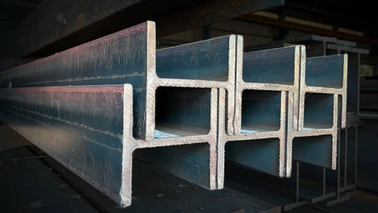
Residual Stress from Rolling and Cutting
Steel beams are typically produced through hot rolling processes, which introduce residual stresses within the material. These internal stresses may not be visible initially but can manifest during cutting, handling, or welding.
For example, flame cutting or CNC cutting can release these stresses unevenly, causing slight curvature changes along the beam. Over long lengths, these small deviations can accumulate and significantly affect camber.
Fabricators must account for these internal forces when implementing steel beam camber control, especially in precision-driven projects.
Welding-Induced Distortion
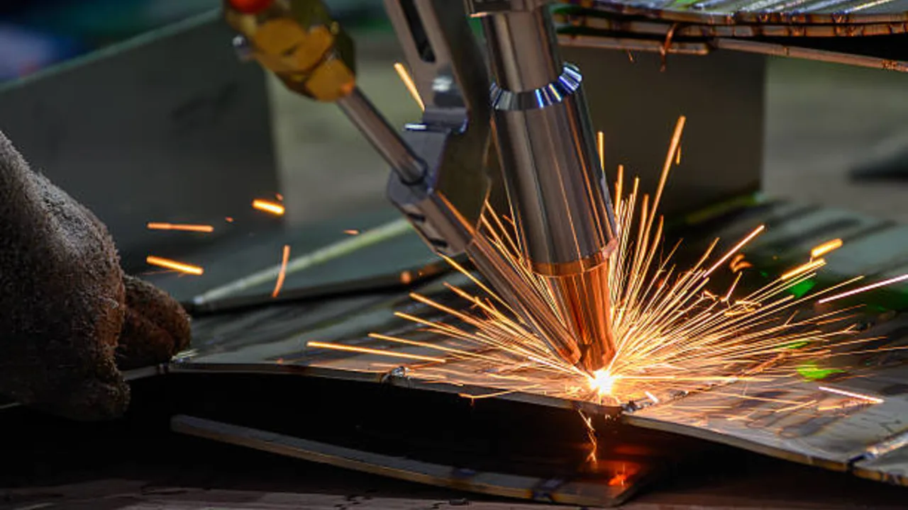
Welding is one of the most influential factors affecting camber. When heat is applied to steel, it expands locally. As it cools, it contracts, often unevenly. This thermal cycle introduces distortion, which can either increase or reduce the intended camber.
Factors that influence welding distortion include:
- Weld size and length
- Heat input and welding sequence
- Material thickness
- Restraint conditions during welding
Improper welding procedures can lead to unpredictable camber deviations, making post-fabrication correction necessary.
Improper Handling and Storage
Even if camber is correctly introduced during fabrication, it can be compromised during handling and storage. Steel beams are often lifted, transported, and stacked multiple times before installation.
Common issues include:
- Improper lifting points causing temporary bending
- Lack of support during storage leading to gradual deformation
- Stacking methods that introduce additional stress
Maintaining beam geometry requires careful handling procedures and proper support systems throughout the supply chain.
Steel Beam Camber Control Methods
Pre-Cambering During Fabrication
Pre-cambering is the most widely used method for achieving the desired curvature. In this approach, beams are intentionally bent upward during fabrication based on calculated deflection values.
The required camber is typically determined using structural analysis that considers:
- Beam span length
- Load magnitude and distribution
- Material properties
- Support conditions
By applying this calculated camber in advance, the beam is expected to level out once installed and loaded.
Mechanical Cambering Techniques
Mechanical cambering involves physically bending the beam using controlled force. This is usually performed with specialized equipment such as hydraulic presses or roller systems.
Common mechanical methods include:
- Hydraulic press cambering for localized adjustment
- Three-point bending systems for uniform curvature
- Roller cambering for continuous shaping
These methods allow precise control over curvature but require skilled operators to avoid over-bending or inducing unintended stress.
Thermal Cambering (Heat Straightening)
Thermal cambering uses controlled heat application to induce shrinkage in specific مناطق of the beam. By heating targeted zones and allowing them to cool, fabricators can manipulate the beam’s geometry.
This method is particularly useful for correcting camber deviations after welding. However, it must be executed carefully to avoid material damage or metallurgical changes.
Key considerations include:
- Temperature control
- Heating pattern
- Cooling rate
When applied correctly, thermal methods provide a flexible solution for fine-tuning camber.
Camber Measurement and Tolerance Standards
Common Measurement Techniques
Accurate measurement is a critical component of effective steel beam camber control. Without reliable measurement methods, even well-executed fabrication processes cannot guarantee compliance with design specifications. Fabricators typically rely on a combination of traditional and advanced measurement techniques depending on project complexity and required precision.
Common measurement methods include:
- String line method: A simple and widely used approach where a taut line is stretched along the beam to measure deviation
- Laser measurement systems: Provide high precision and are commonly used in large-scale or high-tolerance projects
- Dial gauges: Used for localized measurement of camber at specific نقاط along the beam
Each method has its advantages, but consistency in measurement procedures is essential to ensure reliable results across multiple components.
Typical Camber Tolerance Standards
Camber tolerances define the acceptable deviation between the specified and actual curvature of a beam. These tolerances vary depending on project requirements, beam length, and applicable standards.
| Beam Length | Typical Camber Tolerance | Notes |
|---|---|---|
| < 10 m | ±3 mm | Standard fabrication conditions |
| 10–20 m | ±5 mm | Moderate span structures |
| > 20 m | ±8–10 mm | Long-span beams requiring higher control |
Maintaining camber within these tolerances ensures that beams perform as expected during installation and service.
Straightness vs Camber
One of the most common sources of confusion in fabrication is the distinction between camber and straightness. While both relate to beam geometry, they serve different purposes and must be controlled independently.
- Camber: Intentional curvature introduced to counteract deflection
- Straightness: The linear alignment of the beam along its longitudinal axis
A beam can meet camber requirements but still fail straightness criteria, leading to alignment issues during erection. Therefore, both parameters must be monitored simultaneously throughout the fabrication process.
Impact of Poor Camber Control
Structural Performance Issues
Improper camber directly affects how loads are distributed across a structure. When camber is insufficient, beams may sag under load, resulting in unexpected deflection and increased stress in connected elements.
Conversely, excessive camber can create upward forces that alter load paths, potentially causing instability or uneven stress distribution. These issues compromise structural efficiency and may require additional reinforcement.
Installation Problems On Site
Camber inaccuracies often become most visible during erection. Beams that do not align properly can create significant challenges for installation teams.
Typical on-site issues include:
- Difficulty aligning bolt holes and connection points
- Uneven floor or roof surfaces
- Additional time required for adjustments
Such problems can delay project timelines and increase labor costs, especially in large-scale construction projects.
Increased Rework and Cost
When camber deviations exceed acceptable limits, corrective measures become necessary. These may involve mechanical re-cambering, thermal straightening, or even complete component replacement.
Consequences include:
- Additional fabrication time
- Increased labor and equipment costs
- Project delays and scheduling conflicts
Effective steel beam camber control minimizes these risks by ensuring accuracy from the initial fabrication stages.
Best Practices for Steel Beam Camber Control

Planning and Engineering Coordination
Successful steel beam camber control begins long before any material is cut or welded. It starts at the design and engineering stage, where camber values must be calculated with a full understanding of load conditions, span behavior, and structural intent. Engineers are responsible for translating theoretical deflection into practical fabrication requirements, ensuring that each beam will perform as expected once installed.
This process requires precise coordination between structural design teams and fabrication engineers. Any gap between these two disciplines can result in camber misinterpretation, leading to either under-cambered or over-cambered members. In complex structures, especially those involving long spans or irregular geometries, even small misalignments in communication can create compounding errors.
Key considerations include:
- Coordination between structural and fabrication drawings to ensure camber values are clearly defined and consistently interpreted
- Clear definition of camber values, tolerances, and reference points for measurement
- Integration of camber requirements into production planning and sequencing
- Consideration of transport and erection conditions that may influence final beam behavior
Early alignment between design and fabrication teams reduces ambiguity, minimizes rework, and ensures that camber is applied as intended throughout the project lifecycle.
Fabrication Process Control
Once fabrication begins, maintaining camber becomes a matter of strict process control. Steel beams undergo multiple operations—cutting, assembling, welding, and handling—all of which can influence geometry. Without controlled procedures, these processes can introduce unintended curvature or distort the pre-defined camber.
Among all fabrication activities, welding has the most significant impact. The localized heat input causes expansion followed by contraction, which can alter both camber and straightness. Therefore, controlling welding parameters and sequencing is essential for maintaining geometric accuracy.
Best practices include:
- Controlling heat input during welding to minimize thermal distortion
- Applying balanced welding sequences to distribute stresses evenly
- Using fixtures, jigs, and supports to maintain beam geometry during assembly
- Monitoring cumulative effects of multiple weld passes on long-span members
In addition to welding, handling procedures must also be carefully managed. Improper lifting points or insufficient support can introduce temporary or permanent deformation. By maintaining consistent process control, fabricators can prevent unintended camber variation and preserve overall beam quality.
Inspection and Quality Control
Inspection is not a single checkpoint—it is an ongoing process embedded throughout fabrication. Continuous monitoring ensures that camber remains within specified tolerances at every stage, rather than discovering deviations only at final inspection.
Effective inspection systems combine measurement accuracy with procedural discipline. This includes verifying camber after key fabrication steps, especially following welding operations where distortion is most likely to occur.
Inspection activities typically include:
- In-process measurement after cutting, assembly, and welding stages
- Final camber verification prior to delivery or shipment
- Documentation of measurement data for quality assurance and traceability
- Cross-checking camber against straightness to ensure overall geometric compliance
Robust quality control systems are essential for achieving reliable and repeatable results, particularly in projects where structural precision directly affects installation efficiency and long-term performance.
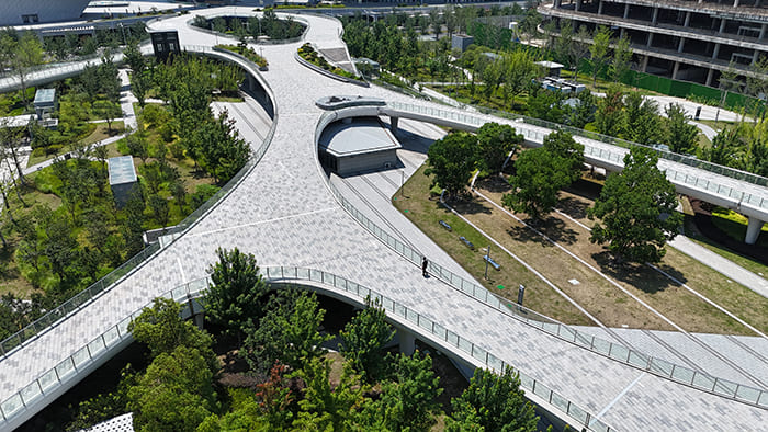
Real Project Insight: Camber Control in Luoyang Guanlin Highway Toll Station
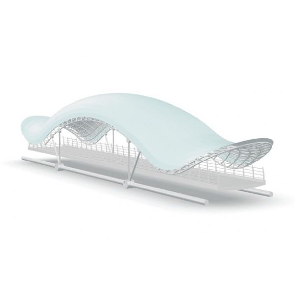
A practical example of effective camber management can be seen in the Luoyang Guanlin Highway Toll Station Spatial Space Grid Structure project executed by XTD Steel Structure. This project involved a complex spatial grid system with long-span steel members that required high precision in both alignment and camber control.
In spatial grid structures, camber control is even more critical than in conventional beam systems. Unlike simple beams, grid structures distribute loads across multiple interconnected members. Any deviation in camber or straightness can disrupt the overall geometry, leading to misalignment at node connections and increased stress concentration throughout the system.
For this project, camber values had to be carefully coordinated during the engineering stage to ensure that each member would align correctly during assembly. Fabrication teams implemented strict process control measures, including controlled welding sequences and the use of specialized fixtures to maintain geometry during assembly.
Additionally, continuous inspection was carried out at multiple stages to verify that camber remained within tolerance. This ensured that when components were transported and assembled on-site, they fit together seamlessly without requiring significant adjustment.
The success of this project highlights how disciplined steel beam camber control contributes not only to fabrication quality but also to installation efficiency. By integrating design coordination, process control, and inspection into a unified workflow, XTD Steel Structure was able to deliver a structurally accurate and reliable system, even under the demanding conditions of a large-scale infrastructure project.