In modern structural engineering, the concept of a steel building load path is fundamental to ensuring safety, durability, and long-term performance. Every steel structure — whether a warehouse, industrial plant, airport terminal, or high-rise building — relies on a clearly defined path through which loads travel from their point of application down to the foundation. Without a properly designed steel building load path, even the strongest steel members can fail due to inefficient force transfer or localized stress concentration.
A steel building load path describes how gravity, wind, seismic, and operational loads move through structural elements in a continuous and uninterrupted manner. From roof panels to beams, from beams to columns, and from columns to foundations, the integrity of this load path determines whether the building behaves as a cohesive structural system. When engineers design a steel structure, they are not merely sizing members — they are orchestrating how forces flow through the entire framework.
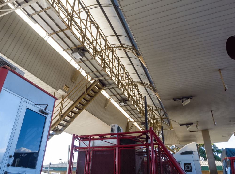
As building spans increase and architectural forms become more complex, the importance of optimized force transfer becomes even more critical. Advanced systems such as space truss configurations have emerged to distribute loads more efficiently across multidirectional frameworks. These innovations highlight why understanding the steel building load path is not optional — it is central to structural stability.
What Is a Steel Building Load Path?
A steel building load path refers to the continuous route through which loads travel from their origin to the ground. It ensures that every applied load — whether vertical or lateral — is transferred safely and efficiently through structural components without interruption. In engineering terms, a load path must be complete, continuous, and capable of resisting all anticipated forces.
The steel building load path begins at the point where loads are applied. For example, roof systems carry dead loads (self-weight), live loads (maintenance activity), snow loads, and wind pressures. These loads are transmitted to purlins, then to primary beams or trusses, then to columns, and finally into the foundation system. Each connection along this route must be designed to accommodate the expected force transfer.
There are two primary categories within any steel building load path:
- Vertical load path – transfers gravity loads downward.
- Lateral load path – resists horizontal forces such as wind and seismic activity.
If either path is incomplete or poorly detailed, structural instability can occur. A discontinuous load path may cause unexpected bending, torsion, or shear forces in members that were not designed for those stresses.
Primary Types of Loads
Understanding the steel building load path requires identifying the types of loads acting on the structure:
- Dead Load: Permanent structural weight including steel members, cladding, roofing systems.
- Live Load: Temporary loads such as maintenance crews or movable equipment.
- Wind Load: Lateral pressure and suction acting on building surfaces.
- Seismic Load: Inertial forces generated by ground acceleration.
- Snow Load: Accumulated snow weight on roof surfaces.
Each of these loads follows a distinct but interconnected steel building load path. Engineers must verify that all paths converge safely at the foundation without overstressing intermediate components.
Fundamentals of Force Transfer in Steel Structures

At its core, structural engineering is about force transfer. In steel buildings, force transfer occurs through beams, columns, bracing systems, and connection details. The efficiency of the steel building load path depends heavily on how these components interact.
For vertical loads, gravity forces travel from roof decking into secondary members (purlins or joists), then into primary beams or trusses, then into columns, and ultimately into the foundation. For lateral loads, the force transfer mechanism becomes more complex. Wind or seismic forces are transferred through diaphragms and bracing systems before reaching vertical resisting elements.
Connections play a decisive role in maintaining the steel building load path. Welded and bolted joints must be designed not only for strength but also for stiffness and ductility. A poorly detailed connection can interrupt force transfer, leading to stress concentrations and potential progressive failure.
Why Continuous Load Paths Matter
A continuous steel building load path ensures:
- Uniform distribution of structural stresses.
- Reduced risk of localized overload.
- Improved resistance against extreme events.
- Greater redundancy and safety margin.
When force transfer is smooth and uninterrupted, structural members work together as a unified system. Conversely, discontinuities in the load path may cause secondary members to carry unintended loads, increasing fatigue risk over time.
Vertical Load Path Design in Steel Buildings
The vertical steel building load path primarily handles gravity-based forces. Engineers must confirm that every vertical load is transferred directly and efficiently to the foundation.
Typical vertical force transfer sequence:
- Roof cladding →
- Purlins or joists →
- Primary beams or trusses →
- Columns →
- Base plates and anchor bolts →
- Foundation system
Beam-to-column connections are especially critical. The load path must remain aligned to prevent eccentric loading, which can induce unwanted bending moments. Foundation anchorage must also be designed to resist compression and uplift forces, particularly in regions exposed to high wind.
In large-span facilities such as hangars or stadiums, vertical load distribution often relies on truss systems. When properly engineered, these systems enhance the efficiency of the steel building load path by spreading forces across multiple members instead of concentrating them in single beams.
Lateral Load Path and Structural Stability
Lateral stability represents one of the most complex aspects of steel building load path design. Unlike gravity loads, lateral forces attempt to push, pull, or twist the structure horizontally. Wind and seismic forces can create overturning moments and shear forces that must be carefully managed.
A lateral steel building load path typically includes:
- Roof or floor diaphragm action.
- Horizontal collectors or drag struts.
- Vertical bracing systems or moment frames.
- Foundation anchorage resisting uplift and sliding.
Bracing systems are essential for ensuring effective force transfer under lateral loads. Cross-bracing, K-bracing, or portal frame systems redirect horizontal forces into vertical members. The design must account for load reversals during seismic events, requiring ductile detailing.
In advanced architectural designs, space truss frameworks provide multidirectional stability. By distributing forces in three dimensions, a space truss enhances overall structural redundancy and strengthens the steel building load path against unpredictable loading conditions.
The Role of Space Truss Systems in Load Distribution
Among advanced structural systems, the space truss stands out as one of the most efficient mechanisms for optimizing a steel building load path. Unlike traditional planar framing systems, a space truss operates in three dimensions, allowing loads to be distributed across multiple interconnected members simultaneously. This multidirectional force transfer reduces localized stress and enhances overall structural redundancy.
In long-span steel structures such as airports, exhibition halls, stadiums, and hangars, maintaining a reliable steel building load path becomes increasingly challenging due to scale. A space truss system addresses this issue by dividing loads into smaller components that flow through triangular modules. Because triangles are inherently stable geometric forms, they resist deformation under compression and tension, making the steel building load path more predictable and balanced.
Another advantage of space truss configurations is their ability to redistribute loads when a single member experiences overstress. Instead of creating a weak point, the surrounding members participate in force transfer, reducing progressive collapse risk. For engineers designing complex facilities, the integration of space truss systems significantly strengthens the continuity of the steel building load path.
Common Load Path Failures in Steel Buildings
Even well-designed steel structures can experience failure if the steel building load path is misunderstood or poorly detailed. Load path discontinuities are often not visible during construction but may become critical under extreme loading events.
Discontinuous Connections
If beam-to-column joints are not aligned properly, or if connection plates lack sufficient stiffness, the intended steel building load path may be interrupted. This can cause unintended bending moments or shear concentrations.
Improper Bracing Layout
Lateral bracing that does not connect directly into primary columns can create an incomplete lateral steel building load path. As a result, wind or seismic forces may be transferred inefficiently, increasing drift and instability.
Weak Foundation Anchorage
Anchor bolts and base plates represent the final link in the steel building load path. If uplift resistance is underestimated, high wind events may compromise structural stability. Proper anchorage design ensures smooth force transfer into the ground.
Overlooked Secondary Members
Secondary members such as purlins and girts also participate in the steel building load path. Ignoring their structural role may lead to unexpected deflection or localized failure, especially under snow or suction loads.
In most progressive collapse scenarios, failure originates from a disrupted steel building load path rather than from insufficient material strength alone.
Design Optimization Strategies
Modern engineering tools allow designers to analyze and refine the steel building load path before construction begins. Finite Element Analysis (FEA), Building Information Modeling (BIM), and advanced structural simulation software enable detailed visualization of force transfer patterns.
Key optimization strategies include:
- Redundancy: Designing multiple load paths so forces can reroute if one member fails.
- Balanced Distribution: Avoiding excessive force concentration in single members.
- Connection Reinforcement: Ensuring joints are designed for both strength and ductility.
- Integrated Structural Planning: Aligning architectural design with structural logic.
In a well-designed structure steel building, the steel building load path is intentionally simplified. Clear alignment between beams, columns, and foundations reduces eccentricity and improves long-term performance. Engineers often strive for direct load transfer rather than relying on complex secondary redistribution.
Load Path Design Table
The following table summarizes how different loads travel through a typical steel building load path:
| Load Type | Primary Path | Structural Element | Risk if Disrupted |
|---|---|---|---|
| Dead Load | Roof → Beam → Column → Foundation | Rigid Frame System | Excessive sagging or deflection |
| Live Load | Floor → Beam → Column | Composite Beam System | Localized overstress |
| Wind Load | Cladding → Bracing → Frame → Foundation | Braced Frame | Lateral instability |
| Seismic Load | Mass → Moment Frame → Base | Moment-Resisting Frame | Structural collapse |
| Snow Load | Roof → Truss → Column | Space Truss System | Roof overload |
This structured overview highlights how every steel building load path must remain continuous across all loading scenarios.
Future Trends in Steel Building Load Path Engineering
As steel structures evolve, so does the science behind steel building load path design. Emerging technologies are transforming how engineers predict and manage force transfer within complex frameworks.
Smart structural monitoring systems now embed sensors into critical joints and members. These systems measure strain, displacement, and vibration in real time, allowing engineers to validate whether the steel building load path performs as intended.
Artificial intelligence and machine learning algorithms are also being integrated into structural analysis software. These tools optimize force transfer patterns by simulating thousands of load combinations rapidly, identifying inefficiencies in the steel building load path before fabrication begins.
Additionally, high-performance steel alloys with improved ductility allow structures to absorb greater energy during seismic events. When combined with modular construction methods, these materials enable more predictable and efficient load path planning.
Advanced space truss innovations further enhance multidirectional stability. By refining node connections and reducing self-weight, modern space truss systems improve both material efficiency and load path reliability in large-span applications.
Conclusion
The integrity of any steel structure depends on a properly engineered steel building load path. From roof to foundation, every element must participate in a continuous and well-defined force transfer system. Whether handling gravity loads, resisting wind pressure, or absorbing seismic energy, the steel building load path determines how safely and efficiently forces move through the structure.
By understanding vertical and lateral load mechanisms, refining connection detailing, and integrating systems such as space truss frameworks, engineers can enhance structural redundancy and long-term resilience. Disruptions in the steel building load path are often the root cause of failure — not material weakness itself.
As design tools and materials continue to advance, the optimization of steel building load path engineering will remain central to modern steel construction. For developers, engineers, and project owners, mastering load path principles ensures safer, stronger, and more efficient steel buildings for decades to come.