The connection between structural steel and reinforced concrete is one of the most critical zones in any industrial, commercial, or infrastructure project. While steel frames provide flexibility and high strength-to-weight efficiency, concrete foundations deliver mass, stiffness, and stability. The performance of the entire building often depends on how well these two materials interact. This is where steel concrete interface design becomes a decisive engineering discipline rather than a secondary detailing task.
In practice, failures rarely originate in the main structural members. Instead, problems emerge at transition zones — misaligned anchor bolts, insufficient grout thickness, poorly positioned embed plates, or differential settlement between steel columns and concrete foundations. A robust steel concrete interface design ensures proper load transfer, dimensional accuracy, durability, and long-term performance. Whether the project involves heavy industrial facilities or a prefabricated steel structure building, the interface must be engineered with precision from the earliest design stage.
The interaction between steel and concrete is not merely mechanical; it is structural and behavioral. Differences in stiffness, thermal expansion, curing shrinkage, and construction sequencing must be anticipated. A well-executed steel concrete interface design integrates structural calculations, construction tolerances, and coordination between trades to prevent costly site corrections later.
Understanding Steel Concrete Interface Design in Structural Systems
At its core, steel concrete interface design governs how forces move from steel members into concrete supports and vice versa. Steel columns typically rest on reinforced concrete foundations, transferring axial loads, bending moments, and shear forces through base plates and anchor bolts. If this load path is not clearly defined, localized stress concentrations can occur, leading to cracking, bolt slippage, or long-term deformation.
Load transfer mechanisms must be evaluated carefully. Axial compression loads are distributed from the steel column into the base plate and then into the grout layer before reaching the concrete foundation. Shear forces may be resisted by anchor bolts, shear keys, or friction developed through pre-tensioned connections. In moment-resisting systems, bending stresses demand thicker base plates and carefully calculated anchor bolt layouts. Every one of these elements falls under proper steel concrete interface design practice.
Tolerance control is equally important. Steel fabrication tolerances differ from concrete casting tolerances. Anchor bolts embedded in concrete may shift during pouring. Even a few millimeters of deviation can cause significant erection delays. Therefore, steel concrete interface design must include realistic tolerance allowances and installation strategies such as bolt templates and pre-survey alignment verification.
Another aspect involves compatibility of deformation. Concrete undergoes shrinkage during curing, while steel responds immediately to applied loads. Without considering these time-dependent behaviors, the interface may experience unintended stress redistribution. A comprehensive steel concrete interface design addresses these differences through structural detailing and sequencing adjustments.
Types of Steel-to-Concrete Interfaces
There are multiple interface configurations depending on structural function and building type. The most common example is the column base plate connection to a concrete foundation. In this configuration, the steel column is welded to a base plate, which transfers loads into anchor bolts and through a layer of grout into the concrete pedestal. The reliability of this detail depends heavily on precise steel concrete interface design to ensure even pressure distribution.
Another common interface occurs between steel beams and reinforced concrete cores in composite structures. Here, embed plates are cast into the concrete core wall during pouring. Later, steel beams are welded or bolted to these plates. Proper steel concrete interface design ensures that embed plates are positioned accurately and anchored with sufficient depth and stud welding to resist pull-out and shear forces.
In industrial facilities, steel stairs, platforms, and equipment frames are frequently anchored directly into concrete slabs. These connections may use mechanical anchors, cast-in bolts, or welded embed plates. The interface must resist vibration, dynamic loads, and sometimes impact forces. Inadequate steel concrete interface design in these areas can lead to cracking or loosening over time.
Across all these configurations, the principle remains the same: forces must flow smoothly without abrupt stiffness transitions. Base plate thickness, anchor bolt diameter, embed plate configuration, and reinforcement detailing all contribute to effective steel concrete interface design.
Role of Grouting in Steel Concrete Interface Design
Grouting is often underestimated, yet it plays a vital role in steel concrete interface design. After steel columns are positioned and leveled, a non-shrink grout layer is placed between the base plate and the concrete foundation. This grout ensures full contact, eliminates voids, and distributes compressive loads uniformly.
Non-shrink grout materials are engineered for high compressive strength and controlled expansion characteristics. Without proper grouting, loads may concentrate on shims or uneven surfaces, causing localized crushing or long-term settlement. Therefore, specifying the correct grout type, thickness, and curing procedure is a critical component of steel concrete interface design.
Typical grout thickness ranges between 20 mm and 50 mm, depending on leveling requirements and structural demands. Excessively thin grout layers may crack under load, while overly thick layers may reduce stiffness. Surface preparation is also essential. The concrete surface must be clean, roughened if necessary, and free of laitance before grout placement. A disciplined steel concrete interface design approach integrates these site procedures into the engineering documentation rather than leaving them as field improvisations.
Common grouting failures include honeycombing due to improper mixing, inadequate curing leading to shrinkage cracks, or insufficient compaction resulting in voids beneath base plates. Each of these issues compromises the effectiveness of the steel concrete interface design and can reduce the service life of the structure.
Embed Plates and Cast-In Components
Embed plates serve as critical connection points between steel members and concrete elements. During concrete casting, steel plates with welded studs are positioned precisely within the formwork. Once the concrete cures, these plates provide a welding or bolting surface for structural steel attachments. Their geometry, thickness, and anchorage depth must be calculated as part of the overall steel concrete interface design.
Stud welding on embed plates enhances pull-out resistance by mechanically interlocking with the surrounding concrete. The number and spacing of studs must align with design loads. Improper placement or insufficient anchorage may result in premature failure under tension or shear forces. This highlights the importance of integrating embed plate detailing within a coordinated steel concrete interface design strategy.
Position accuracy is critical. Before steel erection begins, survey teams must verify embed plate locations. Even minor deviations can cause alignment conflicts. Advanced projects use digital surveying and BIM coordination to minimize risk. By incorporating verification protocols into steel concrete interface design, engineers reduce site adjustments and rework.
Corrosion protection is another key consideration. Interfaces exposed to moisture or aggressive environments may require galvanization, epoxy coatings, or protective sealants. Since this zone is often partially concealed, preventive measures during steel concrete interface design are far more effective than reactive repairs later.
Construction Sequence and Interface Coordination
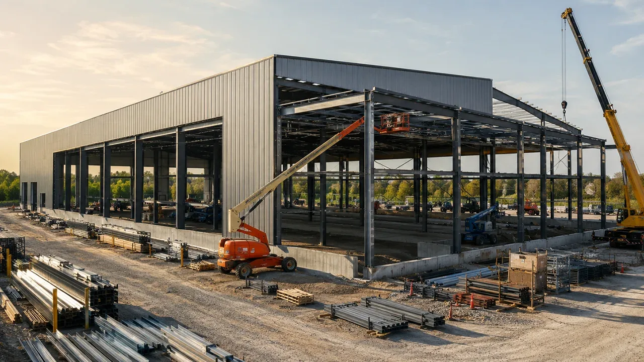
A successful structural project depends heavily on construction sequencing. Even the most technically sound steel concrete interface design can fail if field coordination is weak. Interface zones demand precise timing between civil and steel erection teams to ensure dimensional accuracy and load readiness.
Before concrete pouring begins, anchor bolt templates must be installed and secured to prevent movement during casting. Survey benchmarks should be verified to confirm pedestal elevations and bolt positioning. A disciplined approach to pre-pour inspection is a fundamental step in steel concrete interface design, as anchor bolt misalignment is one of the most common site errors.
Once concrete reaches sufficient strength, steel erection begins. During this phase, column plumbness, bolt torque levels, and temporary supports must be carefully monitored. Improper leveling or premature tightening may introduce unintended stress into the system. Field engineers must confirm that the executed work aligns with the intended steel concrete interface design before proceeding to grouting.
The final locking stage occurs during grout placement. Only after alignment and bolt pre-tensioning are verified should non-shrink grout be applied. At this point, the interface becomes fully load-bearing. This transition from temporary support to permanent structural action represents a critical milestone in steel concrete interface design, activating the intended load transfer path between steel and concrete.
Common Design and Construction Mistakes
Despite its importance, interface detailing is often underestimated. Many structural issues originate from insufficient attention to steel concrete interface design. One frequent mistake involves inadequate anchor bolt projection. If bolts are too short, full nut engagement cannot be achieved, reducing connection reliability.
Another common issue is insufficient grout thickness or uneven grout distribution. Voids beneath base plates create localized stress concentrations, which may lead to cracking or long-term settlement. These problems typically indicate incomplete execution of the specified steel concrete interface design procedures.
Embed plate displacement during concrete pouring is also a recurring challenge. Without rigid fixing or template support, plates may shift slightly, causing misalignment during steel installation. Proper inspection protocols and dimensional verification are essential components of effective steel concrete interface design.
Thermal expansion is another overlooked factor. Steel expands and contracts more noticeably than concrete under temperature changes. If movement allowances are not incorporated, restraint forces can accumulate at the interface. Addressing this within the steel concrete interface design phase prevents long-term cracking or fatigue-related issues.
Steel Concrete Interface Design in Prefabricated Projects
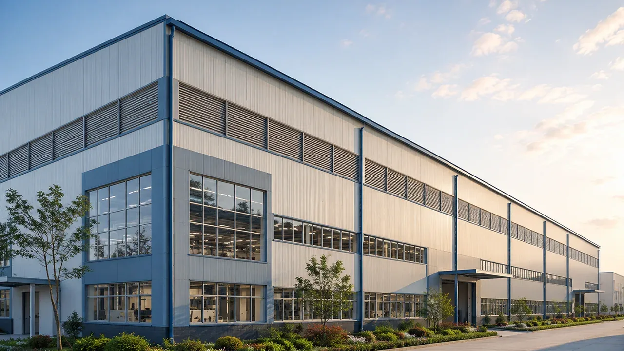
In industrial and modular construction, interface precision becomes even more critical. A prefabricated steel structure building is typically manufactured with high dimensional accuracy in factory-controlled environments. However, the concrete foundation on site may still be subject to construction tolerances. The transition between factory precision and field conditions must be managed carefully through proper steel concrete interface design.
Prefabricated projects often operate under compressed timelines. This increases the importance of coordination between design teams and site supervisors. Anchor bolt positioning, embed plate casting, and foundation leveling must match steel shop drawings exactly. Any deviation can disrupt installation sequences and delay commissioning. Therefore, a comprehensive steel concrete interface design strategy is essential in prefabricated systems.
Modular steel columns, heavy equipment frames, and mezzanine supports all rely on precise base conditions. Because prefabrication reduces on-site adjustments, errors at the concrete stage become more costly. Integrating digital surveys, BIM coordination, and mock-up verification into steel concrete interface design improves installation efficiency and minimizes risk.
In high-load industrial facilities, vibration control is another factor. Machinery foundations require enhanced interface detailing to prevent dynamic load amplification. Reinforced grout layers, shear keys, and anchor bolt pre-tensioning are all evaluated within the framework of advanced steel concrete interface design principles.
Inspection, Testing, and Quality Control
Quality assurance is essential to validate that the executed interface matches the engineered intent. Torque testing of anchor bolts ensures that specified pre-load levels are achieved. Grout cube tests verify compressive strength and curing performance. Weld inspection on embed plates confirms structural continuity. These procedures collectively confirm the integrity of the steel concrete interface design.
Dimensional inspection is equally critical. Survey equipment must confirm base plate elevation, column plumbness, and embed plate alignment. Minor deviations, if uncorrected, may compound under structural loading. Incorporating systematic inspection checkpoints into steel concrete interface design documentation ensures accountability during construction.
Non-destructive testing methods such as ultrasonic testing or magnetic particle inspection may also be applied to welded connections. These verification steps strengthen confidence that the final structure reflects the intended steel concrete interface design without hidden defects.
Long-Term Performance and Maintenance Considerations

The interface between steel and concrete is often concealed after construction, yet it continues to play a crucial role throughout the building’s lifecycle. Moisture ingress, corrosion, and differential settlement can gradually affect performance if not properly addressed during steel concrete interface design.
Protective coatings on base plates, corrosion-resistant anchor bolts, and sealed grout edges reduce exposure risks. Drainage detailing around column bases also prevents water accumulation. These preventive measures, integrated during steel concrete interface design, extend service life and reduce maintenance costs.
Periodic inspection of exposed base plates and anchor nuts is recommended in industrial environments. Any signs of cracking, grout deterioration, or bolt loosening should be investigated promptly. A durable structure is not achieved solely through strong materials, but through thoughtful steel concrete interface design combined with ongoing maintenance planning.
Conclusion
The interface between structural steel and reinforced concrete is far more than a simple connection detail. It is a performance-critical zone that governs load transfer, dimensional stability, durability, and long-term reliability. A comprehensive steel concrete interface design approach integrates structural analysis, material specification, tolerance control, sequencing, and inspection protocols.
From base plate detailing and anchor bolt coordination to grouting and embed plate positioning, every component contributes to structural integrity. Whether applied in heavy industrial facilities or modular construction systems, effective steel concrete interface design reduces risk, prevents costly rework, and ensures that steel and concrete function as a unified structural system.
Ultimately, engineering excellence at the interface level defines the overall success of the project. Investing time and precision in steel concrete interface design is not an optional refinement — it is a structural necessity.