Pratt truss design is not only about choosing a familiar triangular pattern. It is about creating a clear structural system where loads can move from the supported surface into the truss members and then safely toward the supports. When the load path is easy to understand, engineers can size the members, connections, and bracing with better control.
A Pratt truss is widely used because it organizes tension and compression in a practical way. Under common gravity loading, the diagonal members often work mainly in tension, while vertical members and the top chord may carry compression. This makes the system useful for steel bridges, roof structures, industrial galleries, pipe racks, conveyor supports, and other long-span steel structures.
The design should never be treated as a simple diagram. A real truss must respond to actual loads, span length, support conditions, fabrication limits, transportation requirements, and erection sequence. A good truss layout can still perform poorly if connections, bracing, deflection limits, or corrosion protection are not planned correctly.
This guide explains how Pratt truss design works through load paths, diagonal member behavior, component roles, and practical structural use in bridges and steel structures.
What Is Pratt Truss Design?
A Pratt truss is a truss arrangement made of a top chord, bottom chord, vertical members, and diagonal members. The diagonal members typically slope toward the center of the span. This diagonal direction is one of the main features that separates the Pratt form from other truss systems.
In typical downward loading, the diagonals in a Pratt truss often act as tension members. The vertical members often act in compression, and the chords carry axial forces along the top and bottom of the truss. This behavior is one reason the Pratt form has been used for many steel bridge and structural applications.
However, this does not mean every Pratt truss behaves the same way in every project. Real force distribution depends on the exact span, panel spacing, load position, support condition, member stiffness, and load combination. Wind uplift, seismic action, moving loads, and temporary erection loads can change the force pattern. That is why engineering analysis is always required before final member sizing.
In practical steel structure work, Pratt trusses may appear in:
- Pedestrian bridges and access bridges
- Industrial bridge structures
- Roof truss systems for large-span buildings
- Pipe racks and service bridges
- Conveyor galleries
- Equipment support structures
- Open-web steel framing systems
The value of the system is not only its shape. Its value comes from a load path that can be organized, repeated, fabricated, inspected, and maintained.
Main Components in a Pratt Truss
A truss works because each member has a specific role. The top chord, bottom chord, vertical members, diagonals, and gusset plates should not be treated as interchangeable pieces. Each member receives force from the overall truss action and must be designed according to its real demand.
Top Chord
The top chord forms the upper boundary of the truss. Under typical gravity loading, it often works mainly in compression. Because compression members can buckle, the top chord requires careful stability checks. The longer the unbraced length, the more important lateral support becomes.
In roof systems, the top chord may connect with purlins, roof panels, bracing members, or secondary framing. In bridge systems, it may connect with portal bracing, lateral bracing, or cross frames. These connected elements can help stabilize the chord, but they must be coordinated in the design instead of assumed.
A strong top chord is not enough by itself. If the top chord is not properly braced, it may lose stability before the steel reaches its material strength. This is one reason lateral bracing is a major part of Pratt truss design.
Bottom Chord
The bottom chord forms the lower boundary of the truss. It often works mainly in tension under gravity loads. The bottom chord helps tie the truss together and resists the spreading effect created by the overall truss geometry.
Although tension members are generally easier to design against buckling, they still require proper connection detailing. Splice plates, bolt groups, welds, net section strength, and alignment all matter. If the bottom chord is assembled from multiple pieces, the splice locations must be planned carefully so that force can transfer without weakness.
In some project conditions, the bottom chord may also experience force reversal or secondary effects. Wind uplift, seismic loads, lifting conditions, or unusual support movement can change the demand. The design should check these cases instead of assuming simple tension behavior only.
Vertical Members
Vertical members connect the top and bottom chords at panel points. They help transfer loads from the deck, roof system, or secondary framing into the truss. In many Pratt trusses under gravity loading, vertical members often carry compression.
Because vertical members can work in compression, their slenderness and effective length should be checked. A member that looks strong in section size may still be vulnerable to buckling if it is too slender or poorly connected.
Vertical members also help define the truss panel layout. The spacing between vertical members affects panel length, diagonal angle, connection quantity, member force, and fabrication complexity. Good panel planning helps balance structural efficiency with practical production.
Diagonal Members
Diagonal members are the most recognizable part of Pratt truss behavior. In a typical Pratt layout, the diagonals slope toward the center of the span. Under common downward loads, these diagonals usually work mainly in tension.
This is efficient for steel because steel performs very well in tension. A properly designed tension diagonal can transfer force effectively without needing the same compression buckling checks required for compression members. This can help reduce unnecessary member weight and create an efficient open-web structure.
However, diagonal members still need careful design. Their connections must transfer tension safely into the gusset plates and chord members. Bolt spacing, weld size, edge distance, plate thickness, hole alignment, corrosion protection, and fabrication tolerance all affect performance.
Diagonal members should also be checked for load reversal when required. A diagonal that is normally in tension may experience compression under wind, seismic, moving load, or temporary erection conditions. If force reversal is possible, the member cannot be designed only as a simple tension element.
Gusset Plates and Connections
Gusset plates connect the chords, verticals, and diagonals at the truss joints. These connection areas are critical because multiple forces meet at the same location. A truss may have well-sized members, but if the gusset plates or bolts are weak, the full system can still fail to perform properly.
Good connection design should consider member force, bolt or weld capacity, plate thickness, edge distances, hole patterns, fabrication access, erection fit-up, and inspection access. Connections should also avoid unnecessary congestion. A joint that is too crowded can be difficult to fabricate, coat, inspect, and maintain.
In steel truss projects, connection detailing is often where theory meets real construction. Clear drawings, accurate fabrication, and proper field assembly are just as important as the structural calculation.
How Load Paths Work in Pratt Truss Design
A load path describes how force travels through a structure. In a Pratt truss, the load path usually begins at the supported surface, such as a bridge deck, roof system, service platform, or conveyor structure. The load then moves through secondary members into the truss panel points, through web members and chords, and finally into the supports.
A simplified load path may look like this:
- Bridge deck, roof, equipment, or service load
- Secondary framing such as purlins, floor beams, or stringers
- Truss panel points
- Diagonal and vertical web members
- Top and bottom chords
- End supports, columns, bearings, or foundations
The best load path is direct and predictable. Loads should ideally enter the truss at panel points because those joints are designed to transfer axial forces between members. If a load is applied between panel points, it may create bending in a chord or web member that was intended mainly for axial force. This can change the design requirement and increase member size.
Clear load paths help engineers understand which members work in tension, which members work in compression, and which connections carry the largest forces. They also help fabricators and installers understand why certain members, bolts, or bracing pieces cannot be treated as minor accessories.
Gravity Load Behavior
Gravity loads include the self-weight of the structure, deck load, roof load, equipment load, snow load, service systems, maintenance load, and live load from people or vehicles. These loads act downward and are often the main load case considered when explaining basic Pratt truss behavior.
Under common gravity loading, the top chord often carries compression, while the bottom chord often carries tension. The diagonal members typically carry tension, and the vertical members often carry compression. This basic force pattern is one reason Pratt trusses are considered practical for steel structures.
Still, the real design must consider exact loading. A bridge with moving vehicles does not load the truss in the same way as a static roof. A conveyor gallery does not behave exactly like a pedestrian bridge. A pipe rack with concentrated pipe loads may create different force demands from a uniformly loaded roof. The truss must be analyzed for the actual project, not only for a textbook load case.
Wind, Seismic, and Reversed Load Cases
A truss may behave differently when loads do not act straight downward. Wind uplift can reduce or reverse gravity effects in roof structures. Seismic forces can push and pull the structure horizontally. Moving loads can shift the location of maximum force. Temporary lifting and erection conditions can create stress patterns that do not exist after the structure is complete.
These conditions can cause force reversal in some members. A member that is normally in tension may experience compression in another load combination. A connection that seems simple under one load case may need additional capacity when reversed forces are considered.
This is why structural design should include all relevant load combinations. Pratt truss design is reliable when the engineer checks the full range of forces the structure may experience during fabrication, transport, lifting, installation, and service.
Why Diagonal Members Are Important
Diagonal members are one of the most important parts of Pratt truss design. They help transfer shear across the truss panels and move force toward the supports. Without diagonal members, the top and bottom chords would not work together as an efficient triangulated system.
The diagonal arrangement is what allows the truss to replace a much heavier solid beam. Instead of one deep member carrying most of the bending, a truss separates the force into axial tension and compression across multiple members. This makes the structure lighter, more open, and often easier to fabricate in sections.
In a Pratt truss, diagonal members usually slope toward the center of the span. Under common gravity loads, this arrangement often places the diagonals in tension. Since steel is very efficient in tension, the design can use relatively slender members while still achieving strong load transfer.
However, the efficiency of diagonal members depends on more than their angle. The diagonal must connect properly to the gusset plate, the gusset plate must transfer force into the chord and vertical members, and the joint must remain stable under the full range of design loads. A diagonal member that is strong in theory can still become a weak point if the connection is poorly detailed.
Diagonal Direction and Force Flow
The direction of the diagonals is a defining feature of a Pratt truss. In many common layouts, the diagonals lean downward toward the center of the span. This creates a force pattern where diagonals carry tensile forces under downward loading.
This diagonal direction also helps engineers read the structure more clearly. When the load enters the truss at panel points, the force is distributed through the web system and then collected by the chords. The diagonal members help move shear through each panel, while the chords resist the overall bending effect of the span.
The diagonal angle should not be chosen randomly. A very steep diagonal can create different force demands from a shallow diagonal. Panel length, truss depth, span, available clearance, and fabrication limits all affect the final geometry. A practical layout balances structural efficiency with member quantity, connection complexity, and ease of installation.
Tension Members and Fabrication Efficiency
One reason Pratt trusses are popular in steel structure projects is that the diagonal members can often be designed as tension members under primary gravity load cases. Tension members are generally easier to stabilize than compression members because they are not governed by buckling in the same way.
This can support fabrication efficiency. Diagonal members may be lighter, easier to handle, and simpler to repeat across multiple panels. Repetition can reduce fabrication confusion, especially when members are clearly marked and connection details are standardized.
Still, tension members require careful detailing. Bolt holes reduce net section area. Welded connections must be sized correctly. Gusset plates must have enough thickness and edge distance. Corrosion protection must reach joint areas. If fabrication tolerances are poor, field assembly can become difficult and the intended load path may be affected.
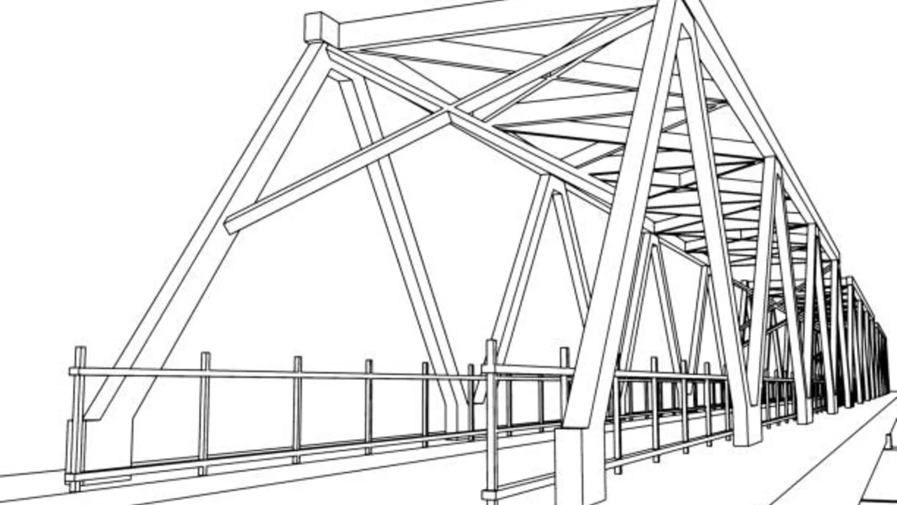
Pratt Truss Design for Bridges
Pratt trusses are strongly associated with bridge design because they can span long distances while keeping the structure relatively open and efficient. In bridge applications, the truss must carry deck loads, live loads, impact effects, wind loads, lateral forces, and long-term durability requirements.
A Pratt truss may be used for pedestrian bridges, access bridges, industrial bridges, pipe bridges, and certain road bridge structures. The exact suitability depends on span length, traffic load, clearance requirement, fabrication capability, transportation method, and maintenance plan.
For bridges, the truss is not just a visual frame at the side of the deck. It is part of a complete structural system. The deck, floor beams, stringers, lateral bracing, bearings, and foundations must all work with the truss. If one part of the system is poorly coordinated, the entire bridge can become less efficient or harder to maintain.
Deck Load Transfer
Bridge deck loads must move into the truss through a planned path. In many bridge systems, loads travel from the deck into stringers, then into floor beams, and then into panel points of the truss. This keeps the main truss members working mainly in axial force.
If loads are introduced between panel points without proper checking, bending may be created in members that were not intended to act like beams. This can increase stress, deflection, and connection demand. For this reason, deck framing and truss geometry should be coordinated early in design.
Deck drainage also matters. Poor drainage can expose steel joints and lower chord areas to standing water, dirt, and corrosion. For bridges, good detailing must consider not only the initial strength of the truss, but also the long-term condition of the steel.
Maintenance and Inspection
A bridge truss should be easy to inspect. Open-web geometry gives inspectors visual access to many members, but connection areas can still become difficult to maintain if details are too crowded. Bolts, welds, gusset plates, splice locations, bearings, and coating systems should be accessible.
Maintenance planning should include corrosion protection, repainting access, drainage paths, fatigue-prone details, and possible replacement of smaller components. A bridge may be structurally efficient when first built, but if it is hard to inspect or protect, long-term maintenance costs can increase.
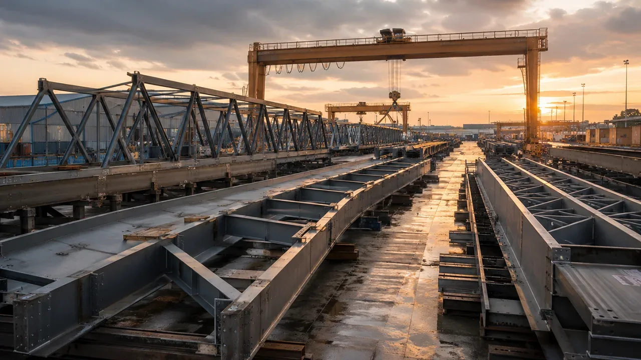
Pratt Truss Design for Industrial Steel Structures
A Pratt truss is also useful outside bridge projects. In industrial steel structures, it can support roof systems, pipe racks, conveyor galleries, crane-related framing, equipment platforms, service bridges, and other long-span structures.
Industrial projects often need open space, long service routes, or reduced intermediate supports. A truss can provide this span capacity without using an extremely heavy beam. It also allows services, ducts, pipes, cables, or maintenance access to pass through or around the open web, depending on the layout.
In this context, Pratt truss design should consider not only structural strength, but also operation. Industrial loads may include vibration, moving equipment, thermal movement, concentrated loads, suspended systems, maintenance access, and future modification needs.
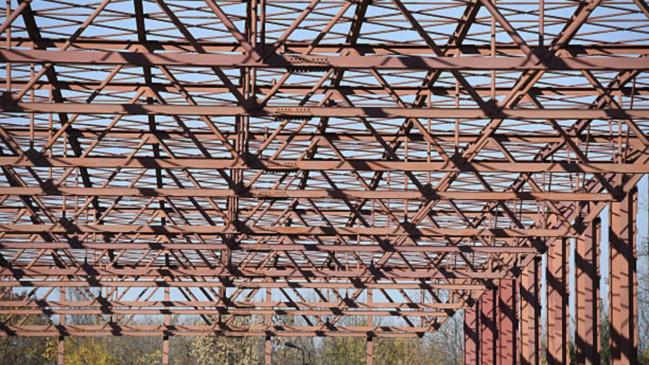
Long-Span Roof Systems
For industrial roofs, Pratt trusses can help reduce the need for interior columns. This is useful in warehouses, factories, workshops, logistics buildings, and production halls where open floor space is valuable.
A roof truss must support purlins, roof panels, insulation, suspended lighting, ducts, cable trays, maintenance loads, and environmental loads. The design should also check wind uplift, roof diaphragm action, lateral bracing, and erection stability.
During installation, the roof truss may not be fully stable until bracing and secondary members are installed. Temporary bracing may be required to keep the truss aligned and safe. A strong final design can still be dangerous during erection if the temporary condition is ignored.
Pipe Racks and Conveyor Galleries
Pipe racks and conveyor galleries often need to cross roads, production zones, storage areas, or open spaces. A truss system can support these long service routes while keeping the structure lighter than a solid girder solution.
For pipe racks, designers must consider concentrated pipe loads, thermal expansion, vibration, maintenance access, and future pipe additions. For conveyor galleries, designers must consider moving load, belt vibration, maintenance platforms, dust, environmental exposure, and alignment requirements.
These structures often operate in harsh industrial environments. Corrosion protection, drainage, access platforms, and connection inspection should be planned from the beginning.
Pratt Truss Design vs Warren Truss Design
Pratt and Warren trusses both use triangular geometry, but they organize their web members differently. Compared with a Warren truss, a Pratt truss design often gives engineers a clearer separation between diagonal tension behavior and vertical compression behavior under common gravity loads.
A Pratt truss typically includes vertical members and diagonals that slope toward the center of the span. Under typical downward loads, the diagonals often work in tension. A Warren truss uses a repeated triangular pattern with alternating diagonals. Depending on the load position, Warren truss diagonals may experience either tension or compression.
Neither system is always better. The right choice depends on the span, loading pattern, deflection limit, fabrication method, connection complexity, inspection needs, and architectural requirements. A Pratt truss may be preferred when diagonal tension behavior and clear panel-point load transfer are important. A Warren truss may be preferred when a simpler repeated triangular pattern fits the project better.
The comparison should always be made as part of the complete structural system. The selected truss type must match the deck, roof, support conditions, lateral bracing, transportation plan, and installation method.
Key Engineering Factors in Pratt Truss Design
A good truss is not only a clean drawing. It must be engineered for force, stability, fabrication, transportation, and construction. Several factors should be reviewed before the design is finalized.
Span and Panel Length
Span length affects member force, deflection, truss depth, and erection planning. A longer span usually requires deeper analysis of both strength and serviceability.
Panel length also matters. If panels are too long, member forces and deflection may increase. If panels are too short, the truss may require too many members, gusset plates, bolts, and fabrication steps. The best layout balances structural efficiency with practical production.
Member Sizing
Each member should be sized according to its actual force demand. Tension members require checks for gross section strength, net section strength, connection capacity, and elongation where relevant. Compression members require checks for buckling, slenderness, effective length, and lateral support.
Top chords and vertical members often need special attention because compression behavior can control the design. Diagonal members may seem simple when they work in tension, but they still require proper connection and load reversal checks.
Deflection Control
Long-span trusses must control deflection and vibration. Excessive deflection can affect roof panels, cladding, bridge decks, equipment alignment, drainage, and user comfort. In industrial settings, deflection may also affect conveyors, pipes, suspended equipment, and maintenance platforms.
Deflection limits depend on the application. A roof truss, bridge truss, pipe rack, and conveyor gallery may each have different serviceability requirements. Strength alone is not enough if the structure moves too much during service.
Connection Detailing
Connection detailing can determine whether the truss performs as intended. Gusset plates, bolts, welds, splice plates, hole patterns, and erection clearances must match the force transfer model.
Poor detailing can create many problems: difficult assembly, weak force transfer, corrosion traps, inspection difficulty, and unexpected field modification. Clear shop drawings and accurate fabrication are essential for reliable truss construction.
Lateral Bracing
A truss must be stable out of plane, not only strong in elevation. Lateral bracing helps prevent twisting, buckling, and sideways movement. It is important during both service and erection.
Permanent bracing should be coordinated with roof framing, deck framing, cross frames, diaphragms, purlins, and support conditions. Temporary bracing should be planned for lifting and installation. Ignoring bracing is one of the most serious risks in steel truss projects.
Common Mistakes in Pratt Truss Design
| Mistake | Why It Matters | Better Design Approach |
|---|---|---|
| Choosing a Pratt layout without checking load conditions | A familiar truss form may not match every span, load type, or support condition. | Review span, load combinations, support layout, deflection limits, and erection method before confirming the truss type. |
| Ignoring force reversal | Wind uplift, seismic forces, moving loads, and lifting conditions can reverse forces in some members. | Check all relevant load combinations and design members and connections for possible reversed forces. |
| Underestimating gusset plates | Weak or poorly detailed gusset plates can limit the capacity of the whole truss. | Design gusset plates, bolts, welds, edge distances, and hole patterns with the same care as the main members. |
| Placing loads away from panel points | Loads between panel points can create bending in members intended mainly for axial force. | Coordinate deck, roof, purlins, floor beams, and equipment supports with truss panel points. |
| Forgetting lateral bracing during erection | A truss may be unstable before the full structure is connected. | Plan temporary bracing, lifting sequence, field alignment, and permanent bracing before installation starts. |
| Using poor corrosion protection | Exposed steel trusses can deteriorate at joints, edges, bolts, and drainage areas. | Plan coating, galvanizing, drainage, inspection access, and maintenance requirements based on the project environment. |
When Is Pratt Truss Design a Good Choice?
Pratt truss design can be a good choice when the project needs a clear load path, medium to long span capacity, efficient use of steel tension members, and practical open-web geometry. It is especially useful when loads can be introduced at panel points and when repetitive fabrication is beneficial.
It may be suitable for bridges, roof systems, industrial corridors, pipe racks, conveyor galleries, access structures, and other steel structures that require both span and inspection access. The open form also makes it easier to see many members and connections during maintenance.
However, it is not automatically the best choice for every project. If the structure has unusual loads, severe space restrictions, complex architectural geometry, or fabrication constraints, another truss type may be more practical. The best design is the one that fits the real structural behavior, fabrication process, and installation plan.
Final Takeaway
Pratt trusses remain useful because they combine a clear load path with efficient diagonal member behavior. The system can be strong, practical, and economical when the geometry, members, connections, and bracing are planned together.
A successful truss is not created by the shape alone. It depends on proper member sizing, gusset plate design, lateral stability, deflection control, corrosion protection, fabrication accuracy, and erection planning. When these factors are coordinated, a Pratt truss can provide a reliable solution for bridge structures, industrial roofs, pipe racks, conveyor galleries, and other steel structure applications.
FAQ About Pratt Truss Design
What is the main idea of Pratt truss design?
The main idea of Pratt truss design is to use top and bottom chords, vertical members, and diagonal members to create a clear load path. Under common gravity loads, the diagonals often work in tension, while some vertical members and the top chord may work in compression.
Why are diagonal members important in a Pratt truss?
Diagonal members transfer shear across the truss panels and help move loads toward the supports. In a typical Pratt layout, the diagonals often work as tension members, which can be efficient for steel structures.
Is Pratt truss design suitable for bridges?
Yes. Pratt truss design can be suitable for pedestrian bridges, access bridges, industrial bridges, pipe bridges, and some road bridge structures, depending on span, load, clearance, fabrication method, and maintenance requirements.
Can Pratt trusses be used in industrial buildings?
Yes. Pratt trusses can be used in industrial roof systems, pipe racks, conveyor galleries, service bridges, platforms, and long-span steel framing where open space and efficient load transfer are needed.
What is the difference between Pratt truss and Warren truss?
A Pratt truss usually has vertical members and diagonals that slope toward the center of the span. A Warren truss uses repeated triangular patterns with diagonals that alternate direction. The better option depends on loading, span, fabrication, connection design, and inspection needs.
What is the biggest design risk in a Pratt truss?
One major risk is focusing only on the truss shape while underestimating connection design, lateral bracing, load reversal, and erection stability. These details can control the reliability of the entire truss system.