Truss systems are efficient because their members are arranged to carry force mainly along their own length. Instead of behaving like deep bending beams, truss members divide loads into tension and compression paths that move through chords, diagonals, verticals, nodes, and supports. This is why understanding axial loads in truss structures is essential for roof trusses, industrial buildings, long-span steel structures, and structural systems where member direction directly affects performance.
Member direction matters because a diagonal, vertical, top chord, or bottom chord does not always carry the same type of force. A member may work in tension under gravity load, compression under wind uplift, or experience force reversal under another load case. For engineers, contractors, and project owners, this means truss geometry is not only a visual layout. It is a force path that must be designed, fabricated, connected, and installed correctly.
What Axial Loads Mean in Truss Structures
An axial load is a force that acts along the centerline of a member. In a truss, this usually means the member is either being pulled apart in tension or pushed together in compression. The basic idea is simple, but the design impact can be significant because each truss member depends on direction, length, restraint, and connection accuracy.
In ideal analysis, truss joints are often assumed to act like pinned connections, allowing members to carry axial force with minimal bending. In real steel construction, however, fabrication tolerance, connection detailing, load placement, and node alignment can create additional effects. That is why axial loads in truss structures must be reviewed together with practical fabrication and installation conditions.
Tension in Truss Members
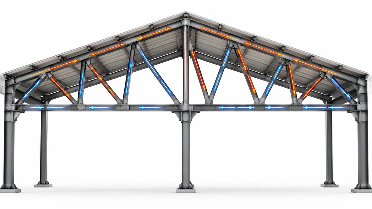
Tension occurs when force pulls a member along its length. Bottom chords, tie members, and some diagonal web members commonly work in tension under typical roof gravity loading. Tension members are usually efficient because they are less sensitive to buckling than compression members. However, they still require checks for net section area, bolt holes, weld strength, gusset plate capacity, and elongation control.
Compression in Truss Members
Compression occurs when force pushes inward along a member. Top chords, compression diagonals, vertical members, and some web members may carry compression depending on the truss type and loading direction. Compression members must be checked for buckling, slenderness ratio, unsupported length, and lateral restraint. A member may have enough steel area but still fail if it is too slender or poorly restrained.
Why Direction Changes Member Behavior
The same member category can behave differently depending on how it is placed. A diagonal that slopes one way may work mainly in tension, while a diagonal with the opposite slope may work mainly in compression under similar vertical loading. When wind uplift, seismic load, crane movement, or suspended load is added, the force direction can change again.
Why Member Direction Matters in Truss Design
Truss efficiency depends on geometry. The angle of a diagonal member, the position of vertical members, the slope of the top chord, and the spacing of panel points all influence how force moves from the load point to the support. Even a small change in member direction can change whether the member mainly carries tension, compression, or alternating force.
In roof trusses, loads often enter the structure through roof panels, purlins, and secondary framing. If those loads are transferred near panel points, the truss can work more efficiently as an axial force system. If loads are placed between panel points, bending may be introduced into members that were intended to carry axial force. This is one reason truss layout, purlin spacing, and node coordination must be planned together.
Common Axial Load Paths in Roof Trusses
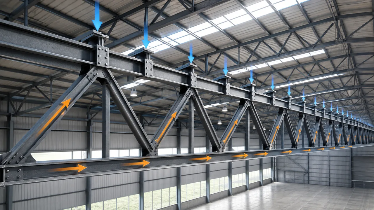
A typical roof truss receives load from the roof system and transfers it toward the supports. Roof panels transfer load to purlins. Purlins transfer load to the top chord or panel points. The top chord usually receives compression under gravity load. Web members then distribute forces through the internal triangular layout. The bottom chord often works in tension, tying the system together and controlling outward spread.
From there, support reactions move into columns, bracing systems, base plates, anchor bolts, and foundations. When this load path is clear, the truss can achieve long spans with efficient steel usage. When the load path is interrupted by poor detailing, misalignment, or weak connections, the member force distribution may become unsafe or less predictable.
Top Chord, Bottom Chord, and Web Member Behavior
Top Chord Members
The top chord follows the roof slope and commonly carries compression under gravity loading. Because it is a compression member, it must be checked for buckling and lateral restraint. Purlins, roof bracing, and secondary framing often help restrain the top chord, but their spacing and stiffness must support the actual design requirement.
Bottom Chord Members
The bottom chord usually acts as a horizontal tie and commonly carries tension. In some roof systems, the bottom chord may also support suspended ceilings, mechanical services, or maintenance access. These additional loads must be considered because they may introduce local bending or additional axial demand.
Diagonal Web Members
Diagonal web members are highly sensitive to direction. Their slope determines how they participate in transferring shear and axial force between the top and bottom chords. Depending on the truss type, diagonals may be designed mainly for tension, compression, or force reversal.
Vertical Web Members
Vertical members help maintain panel geometry and transfer forces between chords. In some truss types, verticals carry compression; in others, they may carry tension. Their behavior depends on the direction of diagonals, the support condition, and the loading pattern.
How Diagonal Direction Affects Tension and Compression
Diagonal direction is one of the biggest differences between truss systems. A diagonal sloping toward the support may respond differently from one sloping away from the support. This direction affects whether the member carries tension or compression under typical roof loading.
In many roof and bridge applications, Pratt truss design is often discussed because its diagonal members are arranged to carry tension efficiently under common gravity loading. In a Howe truss, the diagonal direction is reversed, which changes the force behavior of the diagonals and verticals. Warren and Fink trusses use different triangular arrangements, creating different patterns of axial force distribution.
Axial Loads in Pratt, Howe, Warren, and Fink Trusses
Pratt Truss
In a Pratt truss, the diagonal members typically slope toward the center of the span. Under common gravity loading, these diagonals often work in tension, while vertical members may carry compression. This arrangement can be efficient when tension diagonals are easier to size and connect than long compression diagonals.
Howe Truss
A Howe truss reverses the diagonal direction compared with the Pratt layout. Under typical gravity load, this can place diagonals in compression and verticals in tension. Because compression diagonals require buckling checks, member length and slenderness become important design factors.
Warren Truss
A Warren truss uses a repeating triangular pattern without the same vertical-heavy arrangement found in some other truss types. Its diagonals may alternate between tension and compression depending on loading and location. Warren trusses can be efficient, but force reversal must be considered carefully when wind uplift or asymmetric loading is possible.
Fink Truss
A Fink truss is common in roof framing because its web arrangement helps distribute roof loads toward the supports. It uses a subdivided triangular layout that can reduce member length and improve load distribution. However, each web member still needs to be checked based on its actual direction and force demand.
Axial Loads in Space Truss Systems
A space truss distributes forces in three dimensions instead of one flat plane. This makes it suitable for large-span roofs, stadiums, terminals, exhibition halls, and industrial halls where the roof must cover a wide area with fewer interior supports. In a space truss, many members connect at nodes from different directions, and each member is usually designed for axial tension or compression.
Member direction becomes even more important in a three-dimensional system because each node receives force from several angles. The structure depends on accurate node geometry, controlled fabrication tolerance, and precise installation. If members do not align properly at the node, unintended bending or secondary stress may reduce performance.
Key Design Checks for Axial Truss Members
Reliable design requires more than identifying whether a member is in tension or compression. Engineers must check strength, stability, slenderness, connection capacity, and possible force reversal. These checks help ensure that axial loads in truss structures are transferred safely through the complete system.
Member Strength
Each truss member must have enough steel area and material strength to resist the design axial force. For tension members, net section checks are important because bolt holes can reduce the effective area. For compression members, section strength must be reviewed together with stability.
Buckling Stability
Buckling is one of the most important checks for compression members. Top chords, compression diagonals, and compression verticals can lose stability before reaching full material strength. Lateral restraint, unsupported length, and member slenderness must be evaluated carefully.
Slenderness Ratio
Long and thin members may be efficient for tension, but they can become risky in compression. Slenderness ratio helps engineers evaluate whether a member is too flexible for the required compression force. This is especially important for web members and long roof truss chords.
Connection Capacity
Truss member forces must pass through bolts, welds, gusset plates, node plates, splice plates, and chord connections. If the member is strong but the connection is weak, the load path is still unsafe. Connection details must match member force direction and must avoid excessive eccentricity.
Force Reversal
Some members may change from tension to compression under wind uplift, seismic action, asymmetric load, maintenance loading, or construction-stage conditions. Force reversal is especially important in roof trusses, open industrial structures, and long-span buildings exposed to variable loading.
Comparison of Member Direction and Axial Force Behavior
| Truss Member | Typical Direction | Common Axial Force | Main Design Concern |
|---|---|---|---|
| Top chord | Along roof slope | Compression | Buckling and lateral restraint |
| Bottom chord | Horizontal tie | Tension | Net section and connection force |
| Pratt diagonal | Diagonal toward the span center | Tension under typical gravity load | Bolt and gusset plate capacity |
| Howe diagonal | Opposite diagonal direction | Compression under typical gravity load | Buckling and slenderness |
| Warren diagonal | Alternating diagonal pattern | Tension or compression | Force reversal |
| Space truss member | Three-dimensional member layout | Tension or compression | Node accuracy and load distribution |
Common Mistakes When Evaluating Axial Loads in Trusses
A common mistake is assuming that all diagonal members carry the same type of force. In reality, direction, location, load pattern, and support condition determine whether a diagonal works in tension or compression. Another mistake is ignoring wind uplift, which can reverse member forces and change the critical design case.
Load placement is also important. When loads are applied away from panel points, truss members may receive bending in addition to axial force. This can reduce efficiency and create unexpected stress. Poor node alignment, weak gusset plates, undersized bolts, and missing lateral restraint can also reduce the safety of a truss system.
Why Connection Details Matter for Truss Axial Loads
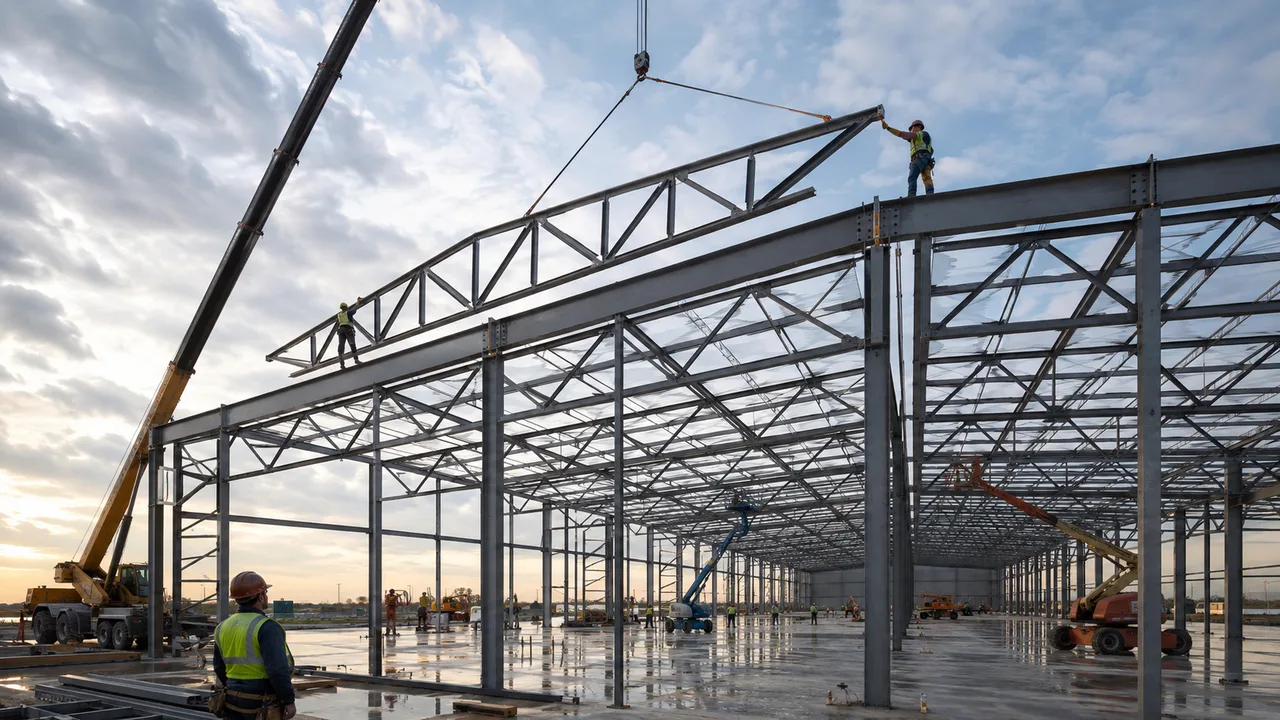
Axial force must pass from one member to another through the connection. This means gusset plate thickness, bolt group capacity, weld size, node plate geometry, and edge distances all matter. The centerlines of connected members should meet as cleanly as possible to reduce eccentricity and unintended bending.
For fabricated steel trusses, connection detailing is where engineering design, shop drawings, workshop fabrication, and site installation meet. Even when the member size is correct, poor connection detailing can interrupt the load path and reduce structural reliability.
How XTD Steel Structure Supports Truss Member Design
For industrial roofs, warehouses, factories, and long-span steel buildings, XTD Steel Structure supports truss member design through structural coordination, member fabrication, connection plate detailing, quality control, and installation coordination. This helps ensure that truss members, gusset plates, node details, and support reactions are reviewed as one connected system.
By coordinating design intent with workshop processing and site assembly, XTD Steel Structure helps improve accuracy in member alignment, connection fit-up, and load transfer. This is especially important for roof trusses and large-span structures where member direction strongly influences axial force behavior.
Practical Takeaway for Truss Structure Projects
Axial loads in truss structures depend heavily on member direction, truss geometry, load placement, and connection accuracy. Top chords, bottom chords, diagonal webs, and vertical members may behave differently under gravity load, wind uplift, seismic action, or asymmetric loading.
A good truss design must check member force, buckling, slenderness, force reversal, and connection capacity together. When the force path is clear and the members are aligned correctly, a truss can deliver strong, efficient, and economical performance for long-span steel construction.
FAQ About Axial Loads in Truss Structures
What Are Axial Loads in Truss Structures?
Axial loads in truss structures are forces that act along the length of truss members, usually as tension or compression. They are the main reason trusses can carry loads efficiently over long spans.
Why Does Member Direction Matter in a Truss?
Member direction affects whether a diagonal or web member carries tension, compression, or force reversal under different load cases. Direction also affects slenderness, buckling risk, and connection design.
Which Truss Members Usually Carry Compression?
Top chords and some diagonal or vertical web members commonly carry compression, depending on truss type, loading direction, and support condition.
Which Truss Members Usually Carry Tension?
Bottom chords and some diagonal members commonly carry tension under typical roof gravity loading. However, force reversal may occur under wind uplift or other load cases.
Can Truss Members Experience Force Reversal?
Yes. Wind uplift, seismic loads, moving loads, asymmetric loading, or construction-stage conditions can reverse the force direction in some truss members.