Plate girders are commonly used where structural systems must carry large bending moments, shear forces, or concentrated reactions over relatively long spans. Their thin webs make them efficient, but those same slender plates can require additional reinforcement in locations where forces enter or leave the girder. Transverse stiffeners are therefore installed at supports, concentrated load points, connection zones, and other critical regions to stabilize the web and provide a more controlled load-transfer path.
One important limit state in these areas is transverse stiffener buckling. A stiffener subjected to compression may become unstable before the steel reaches its full material strength, particularly when the plate is slender, the load is eccentric, or the surrounding web and flange do not provide sufficient restraint. Understanding this behavior requires more than checking the stiffener plate in isolation. The web, flanges, welds, connection plates, fabrication tolerances, and force path all influence the actual structural response.
What Is Transverse Stiffener Buckling?
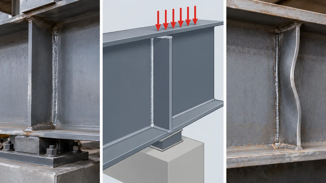
Transverse stiffeners are plates positioned generally perpendicular to the girder flanges and attached to the web. Depending on the structural detail, they may be installed on one or both sides of the web. Their function can include stabilizing slender web panels, supporting concentrated forces, strengthening bearing regions, and transferring reactions between the flange, web, and adjacent connection components.
When a transverse stiffener carries significant compression, it behaves partly like a short compression member. If its stiffness is inadequate relative to its unsupported dimensions and applied force, the stiffener can deflect laterally and lose stability. This instability may occur before a simple yield-strength calculation indicates that the plate is fully utilized.
Role of Transverse Stiffeners in Plate Girders
A properly detailed transverse stiffener can perform several structural functions simultaneously. At a support, it may transfer a large reaction through the girder depth. Within a slender web panel, it can provide a boundary that helps control web deformation. Around a connection, it can distribute local forces and reduce excessive deformation of the web.
The exact role of the stiffener should therefore be established before its capacity is checked. A plate used primarily as an intermediate web stiffener may experience very different forces from a bearing stiffener located directly above a support.
How Buckling Develops
Real stiffeners are never perfectly straight or perfectly loaded. Small plate imperfections, weld distortion, residual stresses, and eccentric force transfer can introduce bending as compression develops. As the load increases, lateral deformation can become progressively larger. Once the available stiffness is insufficient to maintain equilibrium, the stiffener may experience a rapid increase in out-of-plane deformation.
This behavior is particularly important for stiffeners with a large outstanding width relative to their thickness. Their weak-axis stiffness may be much lower than the apparent strength suggested by their gross cross-sectional area.
Buckling vs. Yielding
Yielding and buckling are different limit states. Yielding is primarily controlled by stress relative to the material yield strength. Buckling is strongly influenced by geometry, slenderness, restraint, effective length, initial imperfections, and load eccentricity.
Using higher-strength steel can increase the yielding resistance of a stiffener, but it does not automatically eliminate an instability problem. A poorly proportioned stiffener can still buckle before its material strength is fully developed.
Why Transverse Stiffener Buckling Occurs in Connections
High Concentrated Loads
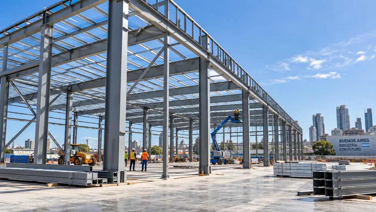
Support reactions, machinery loads, crane forces, connection forces, and other concentrated actions can introduce substantial compression into a relatively small region of a plate girder. If the transverse stiffener forms part of the load path, its compression demand may become significant.
The problem can become more severe when the force is introduced through a flange or connection plate over a short distance, because stress distribution may be highly localized rather than uniform across the stiffener section.
Excessive Stiffener Slenderness
A thin stiffener plate with a relatively large outstanding width may have insufficient resistance to local or overall instability. Increasing plate width without a corresponding increase in thickness can produce a section that has adequate area but poor buckling resistance.
Both plate-element slenderness and the behavior of the stiffener as a compression member should therefore be considered.
Inadequate Restraint
The restraint provided by the web, flange, welds, and opposing stiffener strongly affects stability. If the stiffener terminates without adequate support, is poorly connected to the flange, or relies on an unrealistic restraint assumption, its effective buckling length can be greater than expected.
Connection details should reflect how the stiffener is actually prevented from moving or rotating rather than assuming idealized restraint that cannot develop in the fabricated structure.
Load Eccentricity
Compression is not always applied through the centroid of the effective stiffener section. Misalignment between a bearing plate, connection component, flange, and stiffener can generate secondary bending. Even moderate eccentricity may substantially increase the compression demand on one edge of the stiffener while promoting out-of-plane deformation.
Fabrication Imperfections
Welding can introduce distortion, residual stress, and local plate curvature. Stiffener plates may also have initial flatness or alignment deviations before installation. These imperfections do not necessarily indicate poor fabrication, but they should remain within appropriate project tolerances because compression members are sensitive to initial geometry.
Critical Locations in Plate Girder Connections
End Bearing and Support Zones
Girder supports are among the most important locations for stiffener design. Large reactions must travel from the girder into bearings, columns, brackets, or other supporting components. The stiffener, web, flange, and bearing detail must work together to transfer this force without excessive yielding, crippling, or instability.
Concentrated Load Points
Heavy equipment, crane systems, secondary beams, columns, and suspended structural components can introduce concentrated forces away from the girder ends. Transverse stiffeners may be required at these positions to distribute the force through the girder depth and control local web deformation.
Moment Connection Regions
Moment connections can develop high flange forces combined with significant web shear and local connection forces. When transverse stiffeners are used to reinforce these regions, the load path should account for interaction between the stiffener, web, flange, connection plate, bolts, and welds.
Splice and Connection Zones
Changes in stiffness around bolted or welded splices can alter stress distribution. Connection plates, bolt groups, local cutouts, and nearby stiffeners may create force paths that are more complex than those assumed for a uniform girder section.
Structural Behavior of a Buckling Transverse Stiffener
Compression Force Path
A useful first step in stiffener design is to trace how the applied force moves through the connection. A typical path may be represented conceptually as:
Applied load → flange or connection component → transverse stiffener → web → opposite flange, bearing, or supporting component.
If any part of this path is discontinuous or significantly more flexible than assumed, local deformation can increase and the load distribution may change.
Stiffener-Web Interaction
A transverse stiffener does not always behave as an isolated plate. Depending on the governing design method and detailing, a portion of the adjacent web may participate in the effective compression section. This can improve stiffness and alter the section properties used for stability checks.
However, web participation should be established using the applicable structural design provisions rather than assuming that an arbitrarily large web width contributes to resistance.
Local and Overall Instability
Several forms of instability may be relevant. Individual elements of the stiffener can experience local plate buckling, while the combined stiffener-web section can undergo overall flexural buckling. Web deformation can also interact with stiffener displacement, producing a coupled response.
Post-Buckling Effects
Once significant lateral deformation develops, stresses can redistribute into the surrounding web, flange, welds, and connection plates. The result may be reduced stiffness, increased weld demand, local web deformation, or progression toward another failure mode. For critical connection zones, relying on uncontrolled post-buckling behavior is generally less desirable than providing a clear and adequately restrained load path.
Key Parameters Affecting Buckling Resistance
| Parameter | Effect on Buckling Resistance |
|---|---|
| Stiffener thickness | Increasing thickness generally improves plate stability and sectional stiffness. |
| Stiffener width | A large outstanding width can increase plate slenderness when thickness is unchanged. |
| Steel strength | Higher strength improves yielding resistance but does not by itself prevent instability. |
| Web thickness | Influences local web behavior and the possible contribution of the web to the effective stiffener section. |
| Effective length | A longer effective buckling length generally reduces compression resistance. |
| Weld configuration | Affects restraint and determines how forces are transferred between the stiffener and girder. |
| Load eccentricity | Introduces secondary bending and may accelerate out-of-plane deformation. |
| Initial imperfections | Plate curvature, misalignment, and welding distortion can increase instability sensitivity. |
How Engineers Check Transverse Stiffener Buckling
Determine the Design Forces
The first step is to establish the forces that the stiffener must actually carry. Depending on the connection, this may include a support reaction, concentrated compression, connection force, or a combination of axial compression and bending caused by eccentric loading.
Define the Effective Stiffener Section
The effective section may include one stiffener, a pair of stiffeners, and an applicable portion of the girder web. Section properties should correspond to the actual arrangement and the requirements of the governing design standard.
Evaluate Slenderness
Both local element proportions and overall member slenderness should be reviewed. Important quantities can include stiffener width-to-thickness ratio, effective length, radius of gyration, and the restraint conditions at the stiffener ends.
Check Compression and Buckling Resistance
The design resistance is typically established from the effective compression section together with an appropriate stability reduction related to slenderness. The exact equations depend on the structural design code being used, but the principle remains the same: gross material strength alone is not sufficient when instability can govern.
Check Welds and Load Transfer
Even a sufficiently strong stiffener cannot perform properly if the force cannot enter and leave it. Welds between the stiffener, web, and flange should therefore be checked for the required force transfer. Local bearing, flange behavior, and connection-plate forces should also be reviewed where relevant.
Interaction With Web Buckling and Other Failure Modes
A complete plate girder assessment should not isolate one stability check from the surrounding structural system. Broader stiffener-buckling behavior should be considered together with local web and connection limit states because several mechanisms may compete or interact in the same region.
Web Local Buckling
A slender web may deform locally under compression or shear even when the stiffener itself remains stable. Stiffener spacing, web slenderness, and boundary restraint all influence this behavior.
Web Crippling and Bearing
Concentrated reactions can cause severe local stress near the loaded flange. Web yielding, crippling, or bearing-related failure may govern before the stiffener reaches its full compression resistance.
Stiffener Yielding
A stocky stiffener may avoid instability but still reach its material yield strength under a sufficiently large compression force. Both strength and stability therefore require verification.
Weld Failure
Welds that are undersized, discontinuous where continuity is required, or poorly aligned with the intended force path can limit the capacity of an otherwise adequate stiffener arrangement.
Detailing Strategies to Prevent Buckling
Increase Stiffener Thickness
Increasing plate thickness reduces width-to-thickness slenderness and improves weak-axis stiffness. This is often one of the most direct ways to improve stability, although additional weight and welding requirements should also be considered.
Use Double-Sided Stiffeners
Placing stiffeners on both sides of the web can create a more symmetric arrangement and improve sectional stiffness. This solution can be useful at heavily loaded supports or connection zones when access and fabrication requirements permit.
Improve Flange Restraint
Where the design relies on flange restraint, the stiffener should be detailed so the required force and restraint can actually develop. Fit-up, weld configuration, and stiffener termination all influence the resulting boundary condition.
Reduce Load Eccentricity
Aligning stiffeners with bearings, reactions, and connection-force paths reduces secondary bending. Good geometry can sometimes improve stability more effectively than simply increasing plate size.
Add Supplemental Reinforcement
Bearing plates, doubler plates, additional stiffeners, or reinforced connection components can distribute highly concentrated loads over a larger region. These measures are particularly useful when several local limit states are approaching their design resistance simultaneously.
Control Fabrication Tolerances
Plate straightness, fit-up, weld sequence, and distortion control should be coordinated with the assumptions used during structural design. For fabricated plate girders, manufacturing quality is an important part of achieving the intended stability performance.
Design Example: Transverse Stiffener at a Girder Support
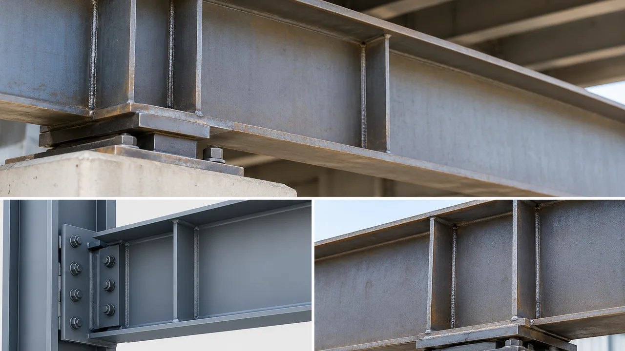
A conceptual design workflow for a bearing stiffener at a support can be summarized as follows:
- Determine the factored or design support reaction.
- Trace the load path through the flange, stiffener, web, and bearing region.
- Select an initial stiffener thickness, width, and arrangement.
- Define the effective stiffener section according to the governing design method.
- Calculate the relevant section properties and radius of gyration.
- Establish the effective buckling length from the actual restraint conditions.
- Evaluate local and overall slenderness.
- Check compression and stability resistance.
- Verify web bearing, yielding, or crippling where applicable.
- Check welds and other connection components for the transferred forces.
- Revise the stiffener geometry or connection detail if any limit state is inadequate.
This sequence emphasizes that a support stiffener is part of a complete connection system rather than an independent plate with a single compression-capacity check.
Common Design and Detailing Mistakes
- Checking only the gross yielding capacity of the stiffener.
- Ignoring weak-axis instability or excessive plate slenderness.
- Assuming perfectly concentric compression when the real force path is eccentric.
- Using an unrealistic effective buckling length.
- Assuming excessive web participation in the effective compression section.
- Providing insufficient connection between the stiffener and adjacent flange or web.
- Using very wide, thin outstanding stiffener plates.
- Ignoring welding distortion, residual stress, and fabrication tolerances.
- Checking the stiffener while overlooking web bearing, crippling, yielding, or weld failure.
When More Detailed Analysis Is Required
Simplified design checks are suitable for many conventional plate girders, but more detailed analysis may be appropriate for very deep girders, extremely slender webs, high concentrated reactions, complex connection geometry, substantial eccentricity, unusual restraint conditions, or fatigue-sensitive structures.
Finite-element analysis can help examine local stress distribution, plate interaction, contact effects, and nonlinear stability when these behaviors cannot be represented adequately with simplified member models. The analysis model should still be based on realistic geometry, boundary conditions, imperfections, material properties, and connection behavior.
Improving Plate Girder Connection Reliability
Reliable connection design requires the stiffener, web, flanges, welds, bearings, and connection plates to be treated as a single load-transfer system. Stability checks should accompany conventional strength checks, especially where thin fabricated plates carry large concentrated forces.
Geometry and detailing are often just as important as steel grade. Adequate stiffness, realistic restraint, controlled eccentricity, and appropriate fabrication tolerances can substantially reduce the risk of instability. During fabrication, XTD Steel Structure coordinates plate processing, welding, dimensional control, and connection detailing so fabricated members can better match the assumptions established during structural design.
For critical connection regions, preventing transverse stiffener buckling is therefore not simply a matter of selecting a thicker plate. The most effective solution comes from understanding the complete force path and ensuring that every component along that path has sufficient strength, stiffness, restraint, and constructability.
Frequently Asked Questions
What Causes Transverse Stiffener Buckling in a Plate Girder?
It can result from high compression, excessive plate slenderness, insufficient restraint, load eccentricity, fabrication imperfections, or a combination of these factors. The surrounding web and flange behavior also influence the stiffener’s stability.
How Is Transverse Stiffener Buckling Different From Web Buckling?
Stiffener buckling primarily involves instability of the reinforcing stiffener or its effective compression section, while web buckling involves instability of the girder web plate. The two mechanisms can interact in heavily loaded or slender plate girder regions.
Does Increasing Stiffener Thickness Prevent Buckling?
Increasing thickness generally improves stability, but it does not solve every problem. Effective length, restraint, load eccentricity, weld detailing, and interaction with the web must also be considered.
Should Transverse Stiffeners Be Welded to Both Girder Flanges?
That depends on the structural function of the stiffener and the governing design requirements. Bearing or force-transfer stiffeners may require direct load transfer to a flange, while intermediate stiffeners can have different termination requirements. The detail should match the assumed structural behavior.
How Is the Effective Length of a Transverse Stiffener Determined?
The effective length depends on the stiffener geometry and the degree of rotational and lateral restraint provided by the flanges, web, welds, and adjacent structural components. The applicable design standard should be used to determine the appropriate stability model.
Can the Girder Web Be Included in the Effective Stiffener Section?
In many design methods, a limited effective width of web may participate with the stiffener. The permitted width and calculation procedure depend on the governing code and the specific stiffener arrangement.
When Are Double-Sided Transverse Stiffeners Required?
Double-sided stiffeners may be selected when higher compression resistance, improved symmetry, greater stiffness, or more effective load transfer is needed. Whether they are required depends on the force level, web geometry, connection arrangement, and applicable structural design provisions.