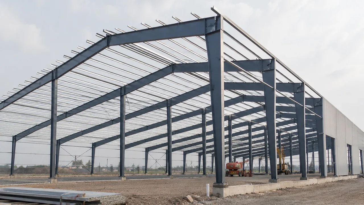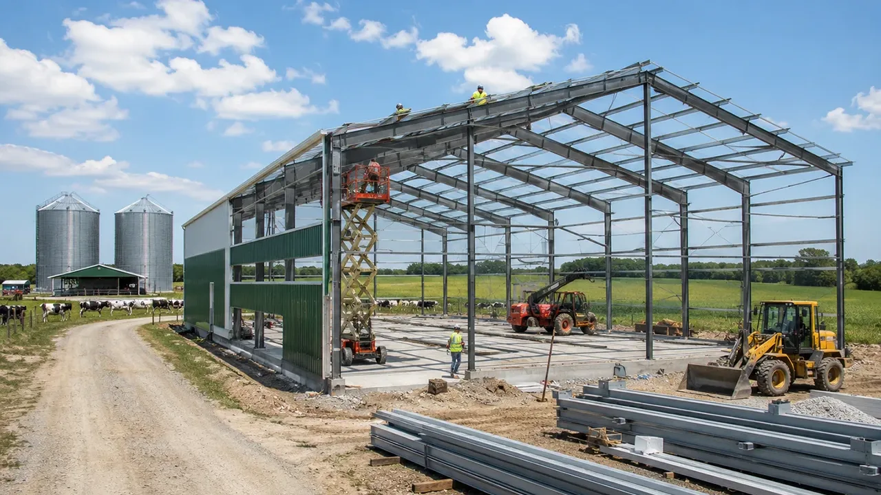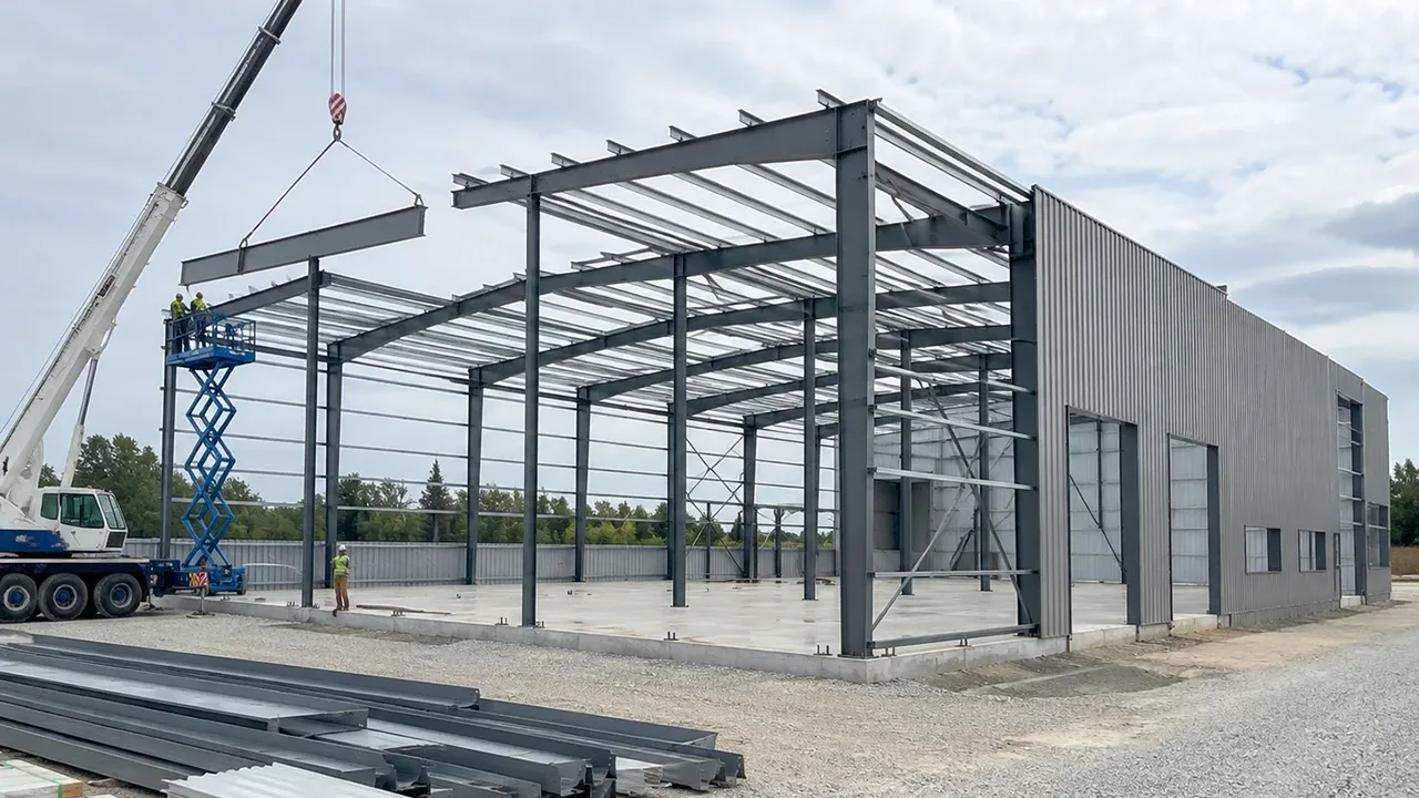
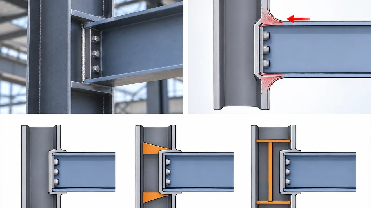
Steel beam-to-column joints can transfer substantial forces through relatively small connection regions. A column may have adequate overall axial, flexural, and shear strength while still developing a localized problem where a beam flange introduces a concentrated force into the column flange. This is why local connection behavior must be evaluated separately from the overall capacity of the structural member.
Flange local bending checks determine whether the loaded flange can resist a concentrated tensile force without excessive local yielding and deformation. The check is particularly relevant to moment connections, where beam flange forces are transferred directly into the supporting column. For industrial steel structures, these forces can become significant in heavy moment frames, crane-supporting buildings, equipment structures, transfer frames, and other heavily loaded systems.
Why Flange Local Bending Matters in Beam-to-Column Joints
A beam moment is transferred through a combination of tension and compression forces at the beam flanges. At the tension flange, the connection may pull outward on a relatively narrow region of the column flange. Although the column section as a whole may be strong enough, the flange plate itself must bend locally to distribute this concentrated force toward the column web.
If the column flange is too thin or flexible, local deformation can develop around the connection. This deformation may alter the intended force distribution, increase demands on welds or bolts, and affect the stiffness of the joint.
Local flange behavior is therefore not simply a secondary detailing issue. It forms part of the complete connection load path. Reliable joint design must consider how the beam flange force enters the column flange, how that force is distributed, and how it ultimately reaches the column web and the rest of the structural system.
What Causes Flange Local Bending
Flange local bending is primarily associated with a concentrated tensile force acting normal to the flange surface. In beam-to-column joints, this condition commonly develops where the tension flange of the beam transfers force through a welded or otherwise concentrated connection.
Beam Flange Tension Forces
When a beam carries moment, one flange is subjected to tension while the opposite flange is subjected to compression. The tensile flange force must pass through the connection and into the supporting column.
If this force is introduced over a limited width, the column flange cannot distribute it uniformly across its entire surface. Instead, the region surrounding the connection bends locally as it transfers the force toward the web.
Concentrated Connection Forces
Directly welded beam flanges, flange plates, and other concentrated attachments can create high local tensile demand. The critical issue is not only the magnitude of the total connection force but also the area and geometry through which that force enters the flange.
A connection that is adequate for weld or bolt strength may therefore still require a separate local check of the supporting flange.
Thin or Flexible Column Flanges
Flange thickness has a major influence on local bending resistance. A thicker flange provides greater resistance to the localized bending mechanism and generally limits deformation more effectively.
Selecting a heavier column section can sometimes eliminate the need for local reinforcement, but increasing the entire member size is not always the most economical solution.
Connection Geometry
Beam flange width, attachment dimensions, loaded width, weld arrangement, and the location of the connection all influence how concentrated forces are distributed.
The actual joint geometry should therefore be used for flange local bending checks rather than relying only on nominal member dimensions.
How Flange Local Bending Develops
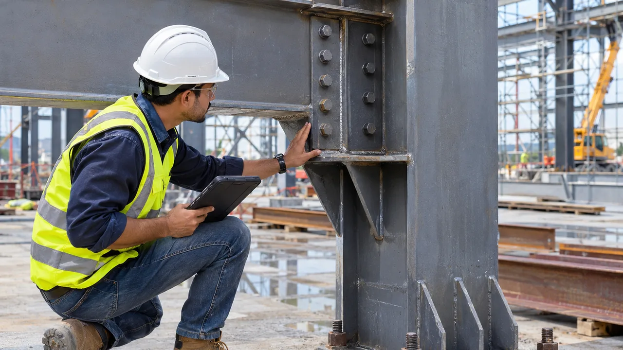
The basic load path can be described as beam, beam flange, connection, column flange, column web, and finally the supporting column.
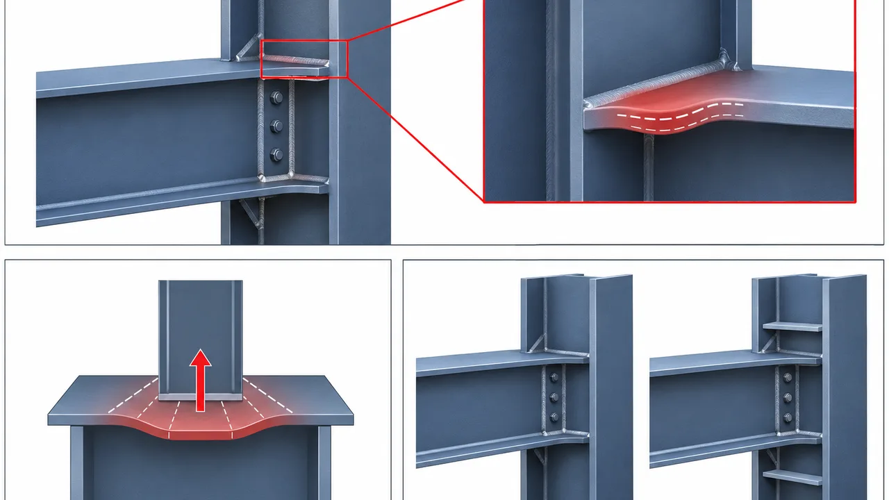
As the tensile beam flange force enters the column, the column flange bends locally around the loaded region. The surrounding flange material provides resistance and distributes the force toward the web. This local plate behavior is different from the overall bending of the column member.
Flange local bending resistance is commonly understood through a yield-line mechanism in which portions of the flange develop localized yielding around the concentrated force. The ability of that mechanism to form depends strongly on the flange thickness, material strength, load location, and available flange geometry.
The AISC connection guidance identifies concentrated flange forces and related column stiffening requirements as part of the local design considerations for beam-to-column-flange moment connections.
When Flange Local Bending Checks Are Required
Flange local bending checks are relevant when a concentrated tensile force acts normal to the flange of the supporting member. Beam-to-column moment joints are a common example because the tensile beam flange force can be introduced directly into the column flange.
The designer should identify the actual direction of the concentrated force rather than automatically performing the same local checks for every connection.
Flange local bending is principally associated with tensile action. Compression forces introduce other local limit states that may govern, particularly within the supporting web. As a result, the tension and compression regions of a moment connection should not simply be treated as identical local conditions.
The position of the connection also matters. A concentrated force located well inside the member can develop a different local resistance mechanism from one located close to an end where less flange material is available for load distribution.
Key Variables in Flange Local Bending Checks
Column Flange Thickness
Flange thickness is one of the most important variables controlling local bending resistance. Because local resistance increases significantly as the flange becomes thicker, relatively small changes in section geometry can materially change the available capacity.
However, increasing the entire column size solely to obtain a thicker flange should be compared with localized reinforcement alternatives.
Flange Yield Strength
The yield strength of the steel affects the resistance available before localized yielding develops. Higher-strength material can increase resistance, but material strength does not replace the need for adequate flange thickness and appropriate connection geometry.
Applied Tensile Force
The required concentrated tensile force should be derived from the actual structural action of the joint. For a moment connection, the flange force is related to the moment transferred through the beam and the internal force couple within the connection.
Using an unrealistic or poorly defined flange force can invalidate the entire local check.
Loaded Width and Connection Detail
The width over which the connection introduces force influences local stress distribution. Beam flange dimensions, connection plates, weld configuration, and other attached components should therefore correspond to the geometry assumed in the design calculation.
Distance From the Member End
Connections near a member end have less surrounding flange material available to participate in the local resistance mechanism. The designer must therefore identify whether the joint behaves as an interior condition or an end condition under the applicable design provisions.
Flange Local Bending Near Member Ends
The location of the concentrated force can materially affect local flange behavior. At an interior location, flange material is available on both sides of the loaded region to participate in force distribution.
Near a member end, the local bending mechanism becomes more restricted because the flange cannot develop the same distribution pattern beyond the end of the member. Treating this condition as an unrestricted interior connection can overestimate the available resistance.
Connection location should therefore be established from the actual fabrication geometry rather than from a simplified structural model alone.
Flange Local Bending vs Other Connection Limit States
Local beam-to-column design includes several related limit states. Although they occur within the same connection region, each represents a different physical mechanism.
| Design Check | Primary Mechanism | Typical Critical Region | Key Variables | Possible Response |
|---|---|---|---|---|
| Flange local bending | Local flange bending and yielding | Loaded column flange | Flange thickness, yield strength, concentrated force | Thicker flange or stiffeners |
| Web local yielding | Localized material yielding | Column web near the loaded flange | Web thickness, load length, material strength | Web reinforcement or stiffeners |
| Web local crippling | Local deformation and instability | Web near concentrated compression | Web slenderness, geometry, load location | Stiffeners or larger section |
| Web compression buckling | Instability under concentrated compression | Column web between loaded regions | Web slenderness, depth, restraint | Web stiffening or section change |
| Panel zone shear | Joint panel shear yielding | Column web within the beam-column joint | Panel geometry, web thickness, joint forces | Doubler plate or larger column |
Passing one local check does not automatically mean the connection satisfies the others. Each applicable mechanism must be considered independently as part of the complete joint design.
When Beam Stiffeners Become Necessary
If the required concentrated force exceeds the available resistance of the unreinforced flange or associated web region, local reinforcement may be required.
Transverse stiffeners or continuity plates can help transfer beam flange forces more directly through the column section. They can also reduce deformation of the flange and create a clearer load path between the beam flange, column flange, and column web.
Where reinforcement is required, proper beam stiffener design should consider the actual governing limit state rather than simply adding plates to the connection. The stiffener itself, its welds, the surrounding flange, and the supporting web must all be capable of transferring the required force.
Stiffeners should therefore be treated as structural load-transfer components rather than isolated fabrication plates.
Stiffener Detailing and Force Transfer
The location of a stiffener should align with the beam flange force whenever the reinforcement is intended to provide a direct transfer path. Misalignment can introduce secondary bending or eccentricity and reduce the effectiveness of the detail.
The stiffener plate must also have adequate thickness and width. Welds connecting the plate to the flange and web should transmit the required design force without creating an unintended weak point.
Fabrication requirements are equally important. Access for welding, plate fit-up, dimensional tolerances, and welding distortion can all affect how closely the completed connection matches the structural design assumptions.
Flange Local Bending in Industrial Steel Structures
Industrial steel structures often contain joints with much larger concentrated forces than ordinary light commercial buildings. Heavy moment frames, crane-supporting structures, equipment platforms, transfer frames, and large-span buildings can all generate significant beam flange forces.
A crane building, for example, may combine gravity, lateral, and dynamic effects within heavily loaded framing. Transfer structures can also concentrate forces from several members into a limited number of beam-to-column joints.
For these projects, XTD Steel Structure coordinates member selection, connection detailing, local reinforcement, fabrication requirements, and dimensional control so that localized joint behavior is considered together with the overall structural system.
Common Errors in Flange Local Bending Checks
A common mistake is to verify the overall column capacity and assume the beam-to-column joint is automatically adequate. Overall member strength and local connection strength are separate design conditions.
Another error is to confuse flange local bending with web local yielding. One involves localized bending of the loaded flange, while the other involves yielding within the supporting web.
Designers should also avoid using an approximate beam flange force that does not reflect the actual joint action, ignoring the effect of a connection located near a member end, or assuming that stiffeners automatically solve every local limit state.
The calculation and the fabricated detail must describe the same load path.
Fabrication and Installation Considerations
Local connection performance depends on fabrication quality as well as structural calculation. Flange thickness, stiffener dimensions, weld size, plate position, alignment, and fit-up should match the approved design and shop drawings.
Welding can introduce distortion, particularly when relatively thick continuity plates or stiffeners are installed within a column section. Appropriate welding sequences and dimensional inspection help control these effects.
During erection, field modifications should also be reviewed carefully. Changes to plates, welds, beam elevations, or connection geometry can alter the concentrated-force path assumed during design.
How XTD Steel Structure Coordinates Beam-to-Column Joint Design
Reliable beam-to-column joints require coordination between structural calculations, connection detailing, fabrication, inspection, and site installation.
XTD Steel Structure integrates these stages by reviewing member geometry, concentrated flange forces, local flange and web behavior, reinforcement requirements, welding details, and fabrication tolerances before structural components are delivered to the project site.
This coordinated approach is particularly valuable for industrial buildings where heavily loaded connections can govern the design even when the primary beams and columns have adequate overall capacity.
Practical Design Takeaway for Flange Local Bending
Flange local bending checks confirm whether a supporting flange can safely transfer concentrated tensile forces without unacceptable localized yielding or deformation.
A reliable design begins with the correct beam flange force, actual connection geometry, column flange thickness, material properties, and connection location. Associated limit states in the supporting web and joint panel should then be evaluated separately.
Where reinforcement is necessary, stiffeners, welds, flanges, webs, and connection plates must work together as one continuous load-transfer system. Local connection capacity should never be assumed solely from the overall strength of the beam or column.
FAQ About Flange Local Bending Checks
What Are Flange Local Bending Checks?
Flange local bending checks evaluate whether a flange subjected to a concentrated tensile force can resist localized bending and yielding without excessive deformation. In beam-to-column joints, the check commonly applies to the column flange receiving force from the beam tension flange.
Where Does Flange Local Bending Usually Occur?
It commonly occurs at localized tension attachments, particularly where beam flange forces are transferred into column flanges in moment connections. Similar behavior can occur wherever a concentrated tensile force acts normal to a flange.
Does a Thicker Column Flange Reduce Flange Local Bending?
Generally, yes. Increasing flange thickness significantly improves local bending resistance and stiffness. However, the complete connection geometry, material properties, force level, and related web limit states must still be checked.
Are Flange Local Bending and Web Local Yielding the Same?
No. Flange local bending involves localized bending and yielding of the flange plate. Web local yielding occurs in the supporting web where the concentrated force is transferred into the member. Both may need to be checked at the same beam-to-column joint.
When Are Stiffeners Required for Flange Local Bending?
Stiffeners may be required when the available local resistance of the unreinforced flange or supporting region is insufficient for the required concentrated force. The reinforcement should be designed according to the actual governing limit state and complete load path.
Does Flange Local Bending Apply to Compression Forces?
Flange local bending is principally checked for concentrated tensile forces. Compression forces can produce different local limit states, including web yielding, crippling, or buckling, which should be evaluated separately when applicable.
Why Are Beam-to-Column Moment Joints Sensitive to Local Flange Bending?
Moment transfer creates relatively large tension and compression forces at the beam flanges. These forces may enter the supporting column through compact connection regions, creating substantial localized demands even when the overall column section remains adequate.
Should Other Local Limit States Be Checked at the Same Joint?
Yes. Depending on the joint configuration and applied forces, web local yielding, web local crippling, web compression buckling, panel zone shear, weld strength, and other connection limit states may also require verification.