Concentrated loads rarely enter a steel member in a perfectly uniform way. Support reactions, equipment loads, moment connections, crane reactions, and other localized forces may introduce high stresses into a relatively small region of a beam or column. In many cases, the overall member has sufficient bending and shear capacity while the web, flange, or connection zone remains vulnerable to localized yielding, crippling, buckling, or deformation.
This is where beam stiffener design becomes important. Instead of increasing the size of an entire beam to solve a local problem, strategically positioned stiffener plates can strengthen the load-transfer zone and improve stability. Depending on the application, stiffeners may reinforce beam webs at supports, stabilize deep web panels, transfer concentrated loads, strengthen column connection zones, or support end-plate moment joints.
A practical design must therefore consider more than plate thickness. The load path, stiffener geometry, web and flange behavior, welds, fabrication access, buckling resistance, and installation sequence all influence whether the final detail performs efficiently.
What Is a Beam Stiffener?
A beam stiffener is a steel plate or structural element attached to the web, flange, or both to strengthen a localized portion of a steel member. Stiffeners are commonly positioned where concentrated forces enter the member or where a slender web requires additional stability.
Rather than increasing capacity uniformly along the full member length, beam stiffeners reinforce selected regions where the existing web or flange alone may not provide sufficient resistance.
Typical applications include support locations, heavy point loads, deep plate girders, beam-to-column moment connections, crane-supporting members, and end-plate joints.
Why Thin Beam Webs Need Local Reinforcement
Modern steel beams can achieve high structural efficiency by concentrating much of their bending resistance in the flanges while using a comparatively thin web to transfer shear. At concentrated load locations, however, that thin web may be exposed to localized limit states such as web yielding and web crippling. AISC design provisions specifically address concentrated-force effects in webs, and research on stiffened girders also identifies yielding and crippling as important design considerations. ([工程期刊][2])
A stiffener can provide a more direct load path, restrain local deformation, divide a slender web into smaller panels, or help transfer forces between the flange and web.
Main Types of Stiffeners Used in Steel Structures
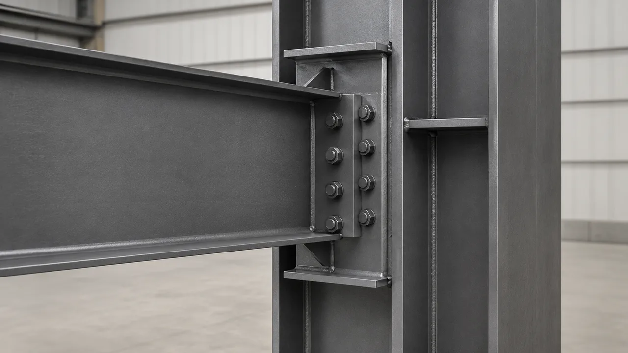
Different structural problems require different stiffener arrangements. Selecting a plate simply because a stiffener “looks necessary” can increase fabrication cost without addressing the governing failure mode.
Transverse Stiffeners
Transverse stiffeners are positioned approximately perpendicular to the longitudinal axis of the beam. They may be installed on one or both sides of the web and are commonly used around supports, concentrated loads, or slender web panels.
They can help provide local reinforcement and improve web stability by reducing the unsupported panel dimensions.
Bearing Stiffeners
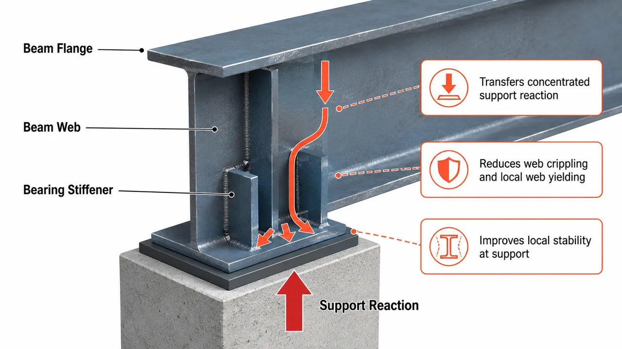
Bearing stiffeners are designed to transfer substantial concentrated compression or support reactions through the beam section. They are commonly located near beam ends, columns, bearings, or heavy equipment support points.
Unlike an intermediate stability stiffener, a bearing stiffener may participate directly in carrying a concentrated force and must therefore have adequate strength, stability, bearing condition, and connection capacity.
Intermediate Stiffeners
Intermediate transverse stiffeners are commonly used in deep fabricated girders where a slender web may buckle under high shear. By dividing the web into smaller panels, the stiffeners help control instability and can contribute to the behavior required for tension-field action where permitted by the applicable design method.
Longitudinal Stiffeners
Longitudinal stiffeners run parallel to the beam axis and are generally associated with deep or slender webs. Their purpose is to improve plate stability by subdividing the web and reducing the effective unsupported width of critical compression regions.
Research has also examined longitudinal web stiffeners as a method of controlling buckling in slender beam webs near moment-frame connections. ([AISC][3])
Connection Stiffeners
Connection stiffeners reinforce localized areas around beam-to-column joints, end plates, flange-force transfer zones, and other heavily loaded connections.
These plates may be positioned to align with beam flanges so that tension and compression forces can pass more effectively into the supporting column or adjoining member.
Where Beam Stiffener Design Is Commonly Required
| Location | Structural Issue | Typical Stiffener |
|---|---|---|
| Beam support | High concentrated reaction | Bearing stiffener |
| Heavy point load | Web yielding or crippling | Transverse stiffener |
| Deep beam web | Shear buckling | Intermediate transverse stiffener |
| Slender plate girder | Web instability | Longitudinal stiffener |
| Beam-to-column joint | Concentrated flange-force transfer | Continuity or connection stiffener |
| End-plate moment joint | Local flange and web deformation | Connection or continuity stiffener |
The important point is that stiffeners should correspond to a clearly identified structural demand. Adding plates everywhere can increase cutting, fitting, welding, inspection, coating work, and fabrication hours without necessarily improving the member proportionally.
Loads That Control Beam Stiffener Design
Support Reactions
At a support, a substantial reaction may pass from the flange into a relatively short length of web. Bearing length, web thickness, flange geometry, support configuration, and reaction magnitude influence whether the unstiffened member is adequate.
Where local web resistance is insufficient, bearing stiffeners can provide an additional path for transferring the reaction.
Concentrated Point Loads
Machinery supports, secondary framing, crane-related loads, suspended equipment, and other point loads can introduce high localized forces into a beam.
Their exact position matters. A load applied near a stiffener or structural node may behave differently from the same load introduced in the middle of an unsupported web panel.
High Shear Forces
Deep beams and plate girders can develop high web shear near supports. When the web is slender, shear buckling can become a governing consideration.
Transverse stiffeners can divide the web into smaller panels and provide boundaries for the web plate, but their spacing and stiffness should follow structural analysis rather than arbitrary repetitive detailing.
Moment Connection Forces
In a moment connection, beam flange forces must enter the supporting column or adjoining member. The tension and compression forces associated with the beam moment can create substantial localized demands on column flanges and webs.
End-plate moment connection guidance specifically addresses stiffened connection arrangements and related local connection behavior. ([AISC][4])
Common Failure Modes Stiffeners Are Designed to Prevent
Web Local Yielding
A highly concentrated load can produce localized yielding in the web adjacent to the loaded flange. The available resistance depends on member geometry, material strength, and the manner in which the load is introduced.
Web Crippling
Web crippling is a localized instability associated with concentrated compression. Research on stiffened webs demonstrates that stiffener depth, load width, loading eccentricity, and the connection of the stiffener can affect behavior under patch loads. ([工程期刊][5])
Web Buckling
A slender web panel can buckle before the steel reaches its full material strength. Transverse or longitudinal stiffeners may be used to improve stability, depending on the geometry and governing loading condition.
Flange Local Bending
Connection forces can cause localized flange deformation, particularly where bolt forces or beam flange forces are introduced over a limited area.
This is especially relevant in moment connections where the stiffness of the supporting flange and surrounding connection components influences joint performance.
Column Web Yielding and Buckling
When a beam transfers large flange forces into a column, the column web may become the weak component even though the column has adequate overall axial and flexural strength.
Continuity plates, local stiffeners, or doubler plates may be introduced when the unstiffened column region cannot adequately resist the connection forces.
Stiffener Buckling
A stiffener is itself a structural plate. Providing sufficient gross area does not automatically guarantee adequate capacity.
Compression stiffeners must also have appropriate proportions and stability so that the reinforcement does not buckle before the required force is transferred.
Basic Beam Stiffener Design Process
A reliable beam stiffener design process begins with the actual load path instead of starting with a predetermined plate thickness.
Step 1 — Identify the Load-Transfer Zone
Determine where the critical force enters or leaves the member. Typical locations include:
- Beam supports
- Heavy point loads
- Beam-to-column connections
- End plates
- Crane or equipment support points
- Transitions in fabricated girders
Step 2 — Check the Unstiffened Member
Before adding reinforcement, evaluate the existing web and flange for the applicable local limit states.
If the unstiffened section already provides adequate capacity and stiffness, adding stiffeners may only increase fabrication complexity.
Step 3 — Determine the Required Reinforcement
If reinforcement is necessary, determine which failure mode controls and what the stiffener must accomplish.
A plate used to stabilize a web panel does not necessarily require the same geometry as a bearing stiffener that directly transfers a large compression reaction.
Step 4 — Select Stiffener Thickness and Width
Plate dimensions should account for:
- Required force transfer
- Plate slenderness
- Buckling resistance
- Available bearing area
- Weld capacity
- Clearance from flange radii
- Available plate thicknesses
- Fabrication access
Simply matching the stiffener thickness to the beam web is not a universal design rule.
Step 5 — Check Stability
Where the stiffener carries compression, evaluate its susceptibility to buckling. The effective structural behavior can involve the stiffener plate together with an adjacent portion of the web depending on the applicable design provisions and detail.
Step 6 — Design the Connections
The stiffener can only perform effectively if the required forces can enter and leave it.
Stiffener-to-web and stiffener-to-flange connections should therefore be designed according to the actual load path rather than using a standard weld size without calculation.
Bearing Stiffener Design at Beam Supports
Bearing stiffeners are particularly important where large support reactions are concentrated into a beam web.
How Bearing Stiffeners Transfer Reactions
The support reaction may pass through the loaded flange into the stiffener and adjacent web before reaching the rest of the beam section.
For this reason, the stiffener should be positioned so that the load path is direct and unnecessary eccentricity is minimized.
Single vs Paired Stiffeners
A single-sided stiffener may be practical for some loading conditions, but paired stiffeners can provide a more symmetrical load path and improve stability where substantial reactions are present.
The choice depends on required capacity, access, connection geometry, and fabrication practicality.
Fitted and Welded Details
Some bearing details rely on close fitting between the stiffener and flange, while others require welded force transfer. The intended structural mechanism must be clear on the fabrication drawings.
Research involving stiffened webs under patch loads also demonstrates that bearing interaction and welded attachment can both influence stiffener behavior. ([工程期刊][5])
Intermediate Stiffeners for Shear Buckling
Deep plate girders can achieve efficient material use by employing relatively thin webs, but web slenderness increases susceptibility to shear buckling.
Intermediate transverse stiffeners divide the web into panels. Their spacing affects panel aspect ratio and therefore the stability behavior of the web.
Where a design relies on post-buckling or tension-field behavior, the stiffener must also provide adequate anchorage and boundary action for the web panel. This makes stiffener rigidity and connection detailing important parts of the overall girder design rather than secondary fabrication decisions.
Longitudinal Stiffeners for Deep and Slender Beams
Longitudinal stiffeners may be introduced when increasing web thickness along the entire member would be inefficient.
They are generally positioned in regions where plate buckling is critical and can work together with transverse stiffeners to divide the web into smaller, more stable plate elements.
Their location should follow the stress distribution and structural analysis. Placing a longitudinal plate at an arbitrary height because it simplifies drafting may provide little benefit if it does not address the controlling compression region.
Column Stiffeners at Beam-to-Column Connections
A beam-column connection must transfer forces through more than the bolts and welds visible at the beam end. The supporting column flange and web also form part of the load path.
Continuity Plates
Continuity plates are commonly positioned approximately in line with the beam flanges. They can help transfer concentrated tension and compression forces across the column section and limit localized deformation.
Their need should be determined from the connection demands and the capacity of the unstiffened column rather than included automatically.
Column Web Doubler Plates vs Stiffeners
A continuity stiffener and a web doubler plate solve different problems.
A continuity plate primarily supports concentrated force transfer near the beam flange level, while a doubler plate reinforces a broader region of the column web where additional panel-zone or local web capacity is required.
In some connections one system may be sufficient; in others, both forms of reinforcement may be required.
Beam Stiffener Design for End-Plate Joints
End-plate connections bring several localized actions together within a relatively compact connection zone. Bolt tension, end-plate bending, beam flange forces, column flange bending, and column web response must be considered as a coordinated system. AISC currently provides dedicated guidance for end-plate moment connection design, including stiffened arrangements. ([AISC][4])
Stiffeners Behind the End Plate
Stiffeners near the beam end can strengthen the local web and flange region and help distribute forces into the beam section.
Their geometry must be coordinated with the end plate, beam flanges, welds, and bolt rows.
Column Continuity Stiffeners
At the supporting column, continuity plates may be aligned with the beam flanges where concentrated tension or compression would otherwise create excessive localized demand.
These plates should not interfere with bolts, access holes, backing, weld execution, or inspection.
Extended End-Plate Connections
Extended end plates position some bolts outside the beam flange region and can develop substantial moment-transfer capacity. Depending on the configuration and connection demand, stiffened end-plate arrangements may be used to control local deformation and achieve the required connection behavior. ([AISC][6])
Stiffener Plate Thickness and Dimensions
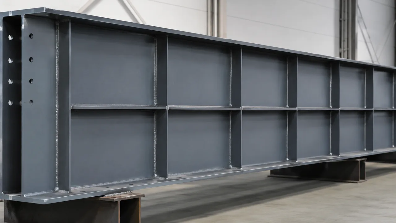
Plate dimensions should follow structural demand and fabrication requirements rather than a fixed proportion copied from another project.
Thickness Selection
The selected thickness must provide sufficient strength and stability while remaining practical to cut, fit, and weld.
Using an excessively thick stiffener can unnecessarily increase weld size, heat input, material cost, and fitting difficulty.
Stiffener Width
The width should provide the required structural area while allowing suitable clearance around flange fillets, rolled-shape root radii, bolts, and weld access.
Corner Cuts and Cope Details
Rolled beams have curved transitions between the flange and web. A rectangular stiffener pushed directly into this radius may not seat correctly.
Corner clips or cope details are therefore commonly coordinated with the actual section geometry so that the plate can be fitted and welded without interference.
Full-Depth vs Partial-Depth Stiffeners
Not every reinforcement plate needs to extend between both flanges.
Partial-depth stiffeners may be appropriate for certain local problems, but their capacity and failure mechanism require careful assessment. Research has shown that partial-depth stiffened webs can still experience crippling under concentrated loading, reinforcing the need to design the actual detail rather than assume any stiffener automatically eliminates the limit state. ([工程期刊][5])
Welding Requirements for Beam Stiffeners
Welds should transfer the forces required by the structural model without adding unnecessary fabrication work.
Stiffener-to-Web Welds
These welds may transfer shear or axial force between the plate and web. Required weld length and size should reflect the force that must be developed.
Stiffener-to-Flange Welds
Where the stiffener must receive load directly from a flange, the connection or specified bearing condition should provide a reliable force-transfer mechanism.
Avoiding Excessive Welding
More welding does not automatically produce a better detail. Excessive weld metal can increase fabrication time, distortion, residual stresses, inspection requirements, and coating repair.
Practical welded fabrication guidance has long emphasized simplifying stiffener arrangements and reducing unnecessary welds where structural requirements permit. ([AISC][7])
Fabrication and Installation Considerations
A structurally adequate stiffener can still become expensive if it is difficult to fabricate.
Designers and fabricators should coordinate:
- Plate cutting tolerances
- Fit-up against flanges
- Welding sequence
- Distortion control
- Bolt and weld access
- Inspection access
- Shop versus field welding
- Coating and galvanizing requirements
- Member straightness after welding
- Identification of repeated stiffener plates
For fabricated steel structures, XTD Steel Structure considers these production constraints alongside structural detailing because a theoretically efficient plate arrangement can lose its economic advantage if it requires excessive fitting and welding.
Beam Stiffener Design Examples by Application
| Application | Main Force or Problem | Typical Solution |
|---|---|---|
| Heavy equipment beam | Concentrated load | Bearing or transverse stiffener |
| Crane support region | High localized reaction | Full-depth bearing stiffener |
| Deep plate girder | Shear buckling | Intermediate transverse stiffeners |
| Long-span fabricated girder | Slender web instability | Transverse and/or longitudinal stiffeners |
| Moment beam-column joint | Flange-force transfer | Continuity stiffeners |
| Extended end-plate joint | High local column or connection demand | Connection stiffeners or continuity plates |
Common Beam Stiffener Design Mistakes
| Mistake | Problem | Better Approach |
|---|---|---|
| Adding stiffeners everywhere | Extra steel, welding, inspection, and cost | Check the unstiffened member first |
| Selecting thickness arbitrarily | Possible buckling or unnecessary material | Size the plate for actual demand |
| Ignoring stiffener stability | Plate may buckle despite adequate area | Check slenderness and compression behavior |
| Poor flange fit | Ineffective bearing-force transfer | Define fitting and welding requirements clearly |
| Ignoring flange root radius | Plate cannot fit correctly | Provide suitable corner cuts or cope details |
| Stiffener clashes with bolts | Connection becomes difficult to assemble | Coordinate plate and bolt geometry early |
| Oversized welds | More heat, distortion, and fabrication work | Design welds for required force transfer |
| Adding stiffeners after fabrication | Rework, coating damage, and schedule impact | Resolve reinforcement during connection detailing |
Beam Stiffeners vs Increasing Beam Size
Stiffeners are not always the most economical solution.
If only one or two localized regions require reinforcement, adding plates may allow an otherwise efficient beam to remain unchanged. This can reduce total steel weight and avoid selecting a much larger section simply to solve a local web problem.
However, if the member requires numerous stiffeners, heavy welds, complicated doubler plates, difficult end details, and extensive inspection, increasing the beam or web size may produce a simpler and less expensive fabricated member.
The comparison should therefore include:
- Steel weight
- Plate cutting
- Fit-up time
- Welding hours
- Inspection
- Surface treatment
- Material availability
- Transportation
- Erection complexity
The lightest structural option and the lowest-cost fabricated option are not always the same.
How to Choose the Right Stiffener Arrangement
A practical selection process can follow these steps:
- Identify the governing concentrated or stability-related load.
- Determine exactly where the force enters the member.
- Check the web and flange without reinforcement.
- Identify the governing local failure mode.
- Select a bearing, transverse, longitudinal, or connection stiffener as appropriate.
- Determine the required plate dimensions.
- Check stiffener slenderness and buckling.
- Design welds, bearing surfaces, and force-transfer paths.
- Coordinate flange radii, bolts, end plates, and fabrication clearances.
- Confirm that the completed detail can be welded, inspected, coated, transported, and erected efficiently.
Beam Stiffener Design: Final Engineering Considerations
Effective beam stiffener design begins with understanding why the local region requires reinforcement. A stiffener intended to prevent web crippling performs a different structural function from an intermediate plate used to stabilize a slender girder web or a continuity plate transferring moment-connection forces through a column.
The correct detail should address the governing failure mode without introducing unnecessary fabrication complexity. Plate thickness, width, stability, welds, bearing conditions, connection clearances, and surrounding member capacity must therefore be considered together.
For steel beams, columns, and end-plate joints, the most efficient solution is not necessarily the detail with the greatest amount of reinforcement. It is the arrangement that provides the required force transfer and stability while remaining practical to manufacture, inspect, transport, and install.
By coordinating structural engineering with fabrication requirements early in the project, XTD Steel Structure can develop stiffener details that strengthen critical load-transfer zones without unnecessarily increasing the weight and complexity of the entire steel member.