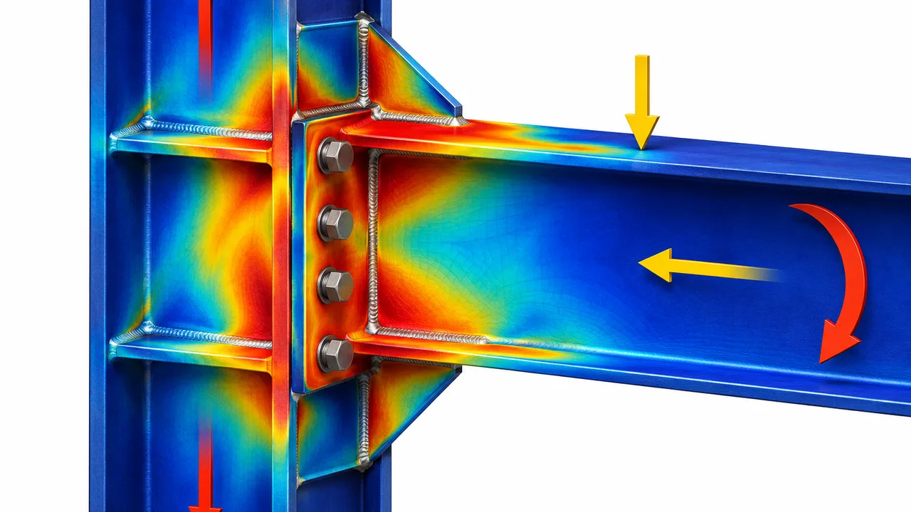
Steel connections transfer forces between beams, columns, braces, plates, and other structural components. Although individual members may have adequate strength, a connection can still become the controlling point of a structural system if one of its components yields, fractures, buckles, slips, or deforms excessively.
Understanding steel connection failure modes requires more than checking bolt or weld strength. Engineers must consider the complete load path, including connection plates, supporting webs and flanges, stiffeners, bolt groups, weld groups, and surrounding base metal. Axial forces, shear, bending moments, eccentricity, and combined loading can each activate different limit states.
This guide explains the principal failure mechanisms found in structural steel connections and the capacity checks used to evaluate them.
Understanding Steel Connection Failure Modes
Why Connection Failure Is Often More Complex Than Member Failure
A steel member generally carries forces through a relatively continuous section. Connections are different because forces must pass through multiple components before reaching the supporting member.
For example, a beam reaction may travel through a connection plate, bolts, the column flange, and finally the column web. Every component has its own strength, stiffness, geometry, and potential failure mechanism.
Stress concentrations around bolt holes, weld ends, plate edges, and changes in section geometry can also create local demands much higher than the average stress calculated for the overall connection.
As a result, connection capacity is normally controlled by the weakest applicable limit state rather than by the nominal strength of a single component.
Strength Failure vs Serviceability Failure
Connection problems can broadly be divided into strength and serviceability limit states.
Strength-related failures include:
- Yielding of plates, webs, or flanges
- Fracture of bolts, welds, or net sections
- Block shear rupture
- Local buckling
- Bearing and tear-out failure
Serviceability-related problems may occur before complete strength failure. These include excessive slip, rotation, plate deformation, connection movement, or local distortion.
A connection may therefore remain technically intact but still perform poorly if deformation becomes unacceptable.
How Load Paths Affect Connection Capacity
The load path describes how force travels from one structural component into another.
A reliable connection must provide a continuous and predictable path for:
- Axial tension or compression
- Vertical and horizontal shear
- Bending moment
- Torsion
- Combined forces
If any component along this path has insufficient capacity, the entire connection may be limited by that component.
Main Categories of Steel Connection Failure Modes
Most steel connection failure modes can be grouped into yielding, fracture, buckling, bearing, local bending, instability, or excessive deformation.
Yielding Failure
Yielding occurs when steel stress reaches its yield strength and permanent deformation begins.
Typical connection yielding mechanisms include gross-section yielding, local web yielding, plate bending, flange yielding, and bearing-induced deformation around bolt holes.
Limited yielding may sometimes permit beneficial redistribution of forces, but excessive yielding can reduce stiffness and eventually lead to another limit state.
Fracture Failure
Fracture is generally more sudden than yielding and is therefore carefully controlled in connection design.
Common fracture mechanisms include:
- Net-section fracture
- Bolt tension or shear fracture
- Weld rupture
- Block shear rupture
- Base-metal fracture near welded regions
Fracture resistance depends on material strength, connection geometry, hole arrangement, weld quality, and stress concentration.
Buckling Failure
Thin connection components subjected to compression may become unstable before reaching their full material strength.
Examples include web buckling, gusset plate buckling, stiffener buckling, and local plate buckling.
Slenderness, unsupported length, boundary conditions, and load distribution strongly influence these failures.
Bearing and Crushing Failure
Bearing occurs where concentrated forces are transferred between components.
In bolted connections, bearing develops between the bolt shank and the side of the bolt hole. Concentrated reactions can also produce web crippling or local crushing in supporting members.
Connection Instability and Excessive Deformation
Some connections lose effectiveness because of excessive rotation or deformation rather than immediate rupture.
Prying action, end-plate bending, bolt slip, flange bending, and local plate distortion are common examples.
Web Local Yielding in Steel Connections
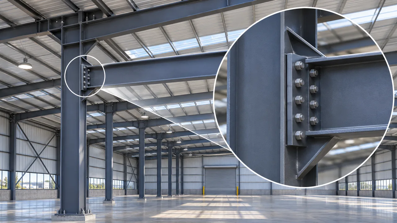
web local yielding occurs when concentrated tension or compression produces stresses in a supporting web that exceed its local yield resistance.
This mechanism is particularly important where beam flange forces, concentrated loads, or support reactions enter a column or beam web.
What Causes Web Local Yielding
High concentrated forces do not spread instantly through the full depth of a supporting member. Instead, they initially act over a relatively limited region.
If the web thickness or yield strength is insufficient, this localized stress can cause permanent deformation.
Typical Locations Where Web Local Yielding Occurs
Common locations include:
- Beam-to-column moment connections
- Column webs opposite beam flanges
- Concentrated load application points
- Beam support reactions
- Connections with short load distribution lengths
Capacity Checks for Web Local Yielding
Capacity is influenced by web thickness, steel yield strength, effective bearing or load distribution length, flange geometry, and whether the load is applied close to the member end.
Engineers must determine the effective portion of the web that participates in resisting the concentrated force and compare its design resistance with the required load.
Methods to Prevent Web Local Yielding
Possible solutions include increasing web thickness, adding transverse stiffeners or doubler plates, increasing the effective load distribution area, or selecting a larger supporting section.
Web Crippling Failure
Web crippling is a local failure caused by concentrated compression near a support, reaction point, or applied load.
Unlike simple yielding, web crippling often involves a combination of local yielding and geometric instability.
How Web Crippling Develops
A concentrated compression force can push the flange and adjacent web inward. As the web deforms, the load path becomes increasingly nonlinear and local crushing or folding can occur.
Difference Between Web Crippling and Web Local Yielding
Web local yielding primarily refers to material yielding caused by concentrated stress. Web crippling involves more substantial local distortion and instability.
The two limit states are related but should not automatically be treated as identical.
Web Crippling Capacity Factors
Important factors include:
- Web thickness and slenderness
- Bearing length
- Distance from the member end
- Flange restraint
- Steel yield strength
Web Buckling Failure
Web buckling can occur when compressive forces create an unstable region within a slender web.
This is particularly relevant around concentrated reactions and moment connection zones.
Compression-Induced Web Buckling
If a concentrated compression force is transmitted through a flange into a thin web, the web may behave like a slender compression element.
Instead of continuing to carry additional load through material strength alone, it may deflect laterally and lose stability.
Web Slenderness and Buckling Capacity
Web depth-to-thickness ratio, unsupported depth, boundary conditions, and the presence of stiffeners all affect buckling resistance.
Improving Web Buckling Resistance
Designers may use transverse stiffeners, thicker webs, local reinforcement, or sections with lower web slenderness.
Flange Local Bending
Flange local bending occurs when concentrated tensile forces pull on a flange and cause it to bend locally.
This behavior is common in bolted end-plate and flange-type moment connections.
How Concentrated Tension Causes Flange Bending
Bolt tension creates localized forces around the bolt lines. If the connected flange is relatively thin, it can deform instead of behaving as a rigid plate.
Flange Thickness and Bending Resistance
A thicker flange generally provides greater local bending resistance and reduces deformation around the bolt group.
However, increasing thickness can also shift the controlling failure mode to the bolts, welds, or supporting web.
Relationship Between Flange Bending and Prying Action
Flange or end-plate deformation can create additional contact forces that increase bolt tension. This phenomenon is known as prying action.
Ignoring prying forces can significantly overestimate connection capacity.
Stiffener Failure Modes
Stiffeners are often added to prevent web or flange failure, but the stiffeners themselves must also be checked.
Stiffener Yielding
A stiffener carrying concentrated compression or tension must have adequate cross-sectional strength to transfer the required load.
Stiffener Buckling
A slender compression stiffener may buckle before its material reaches full yield strength.
Width-to-thickness ratio, unsupported length, and connection restraint are therefore important.
Stiffener-to-Web and Stiffener-to-Flange Weld Failure
Even if the stiffener plate itself is sufficiently strong, its welds must transfer force into the supporting web and flange.
The weld connection should therefore be checked as part of the complete load path.
Bolt Failure Modes in Steel Connections
Bolts can fail through shear, tension, combined loading, bearing-related mechanisms, or slip depending on the connection configuration.
Bolt Shear Failure
Bolt shear occurs when forces act transverse to the bolt axis.
The available resistance depends on bolt strength, bolt diameter, number of shear planes, and whether the threaded portion lies within the shear plane.
Bolt Tension Failure
Bolts in end-plate, flange plate, hanger, and similar connections may experience significant axial tension.
Bolt tensile resistance must be checked against direct tension and any additional force caused by prying action.
Combined Bolt Shear and Tension
Many bolts carry shear and tension simultaneously.
In these cases, checking each force independently may not be sufficient. An interaction relationship is commonly required to account for their combined effect.
Bolt Bearing Failure
Bearing stress develops between the bolt and plate around the hole.
Insufficient plate thickness, small edge distances, or high bolt force can cause permanent elongation or crushing of the hole.
Bolt Hole Tear-Out
When a bolt is positioned too close to a plate edge, the material between the hole and edge can tear out.
Adequate end distance and edge distance are therefore essential.
Bolt Slip in Slip-Critical Connections
Some connections rely on friction between pretensioned surfaces rather than bolt-hole bearing during normal loading.
Insufficient pretension, poor surface preparation, or contamination can reduce slip resistance.
Weld Failure Modes
Welded connections must be evaluated for the direction, magnitude, and distribution of applied forces.
Weld Shear Failure
Fillet welds commonly transfer shear through their effective throat.
Capacity depends on weld size, effective length, weld material strength, and loading direction.
Weld Tension Failure
Groove welds and some weld groups may experience direct tension.
The weld metal and connected base material must both provide sufficient resistance.
Combined Weld Stress
Weld groups frequently resist combinations of axial force, shear, and moment.
The most highly stressed region may be far from the weld group centroid where moment-induced stress is greatest.
Base Metal Failure Near the Weld
A weld can be stronger than the adjacent plate or member.
For this reason, engineers should not stop after calculating weld metal strength. The base metal and heat-affected region must also provide adequate resistance.
Weld Group Failure Under Eccentric Loading
When a load does not act through the weld group centroid, secondary moment develops.
This creates nonuniform stress around the weld group and may greatly increase demand at its extreme points.
Plate Failure Modes
Connection plates can govern capacity even when bolts and welds remain below their design resistance.
Gross Section Yielding
Gross-section yielding occurs when the average tensile stress over the full plate section reaches the yielding limit.
Net Section Fracture
Bolt holes reduce the effective tensile area of a plate.
The remaining net section must be checked against fracture, particularly across critical bolt lines.
Block Shear Failure
Block shear combines shear rupture or yielding along one portion of a failure path with tensile rupture along another.
This mechanism is common near bolt groups at plate ends.
Plate Bending
End plates, gusset plates, flange plates, and connection angles may bend when loads are applied away from their supported region.
Plate Buckling
Thin plates subjected to compression can buckle locally before reaching their full compressive strength.
Gusset Plate Failure Modes
Gusset plates are widely used in bracing and truss connections and may be subjected to complex combinations of tension, compression, shear, and bending.
Gusset Plate Yielding
The plate must provide sufficient gross-section capacity along the effective force path.
Gusset Plate Buckling
Compression braces can introduce forces that cause an inadequately supported gusset plate to buckle out of plane.
Block Shear and Net Section Fracture
Bolt patterns create reduced sections and possible block shear paths that must be checked.
Whitmore Section Capacity
The Whitmore section concept is frequently used to estimate the effective width of a gusset plate resisting axial force from a connected brace.
Connection Eccentricity in Gusset Plates
If the brace force does not align with the connection centroid or expected load path, additional bending may develop.
Failure Modes in Moment Connections
Moment connections transfer significant tensile and compressive flange forces in addition to shear.
Potential failure modes include:
- Bolt tension failure
- Prying action
- End-plate bending
- Column flange local bending
- Column web local yielding
- Panel zone shear
- Beam flange weld failure
Because several components participate in moment transfer, these connections should be evaluated as systems rather than as isolated bolts or welds.
Failure Modes in Shear Connections
Typical shear connections may be governed by bolt shear, bolt bearing, plate tear-out, block shear, weld failure, or local failure of the supporting member.
A simple connection geometry does not necessarily mean the design check is simple. Thin supporting webs and short edge distances can still create critical local limit states.
Failure Modes Under Axial Loads
Tension Connection Failure Modes
Connections subjected to axial tension may be governed by gross-section yielding, net-section fracture, block shear, bolt tension, bolt shear, weld rupture, or plate bending.
The critical mechanism depends on how the tensile force enters and leaves the connection.
Compression Connection Failure Modes
Compression connections may experience bearing, crushing, web crippling, local plate buckling, stiffener buckling, or overall instability of connected elements.
Steel Connection Failure Modes Under Combined Loads
Real structures rarely experience perfectly isolated load cases.
A connection may carry axial force, shear, and moment simultaneously because of frame action, eccentric geometry, lateral loading, or load redistribution.
Combined Axial and Shear Loads
Bolts and welds may be required to resist axial force and shear at the same time.
Interaction checks are necessary where one force reduces the available capacity for the other.
Combined Shear and Moment
Moment produces a varying force distribution across bolt or weld groups, while direct shear adds another demand to the same components.
Combined Tension and Moment
Tension may act uniformly across the connection while moment increases force on one side and reduces it on the other.
Why Individual Load Checks May Be Insufficient
Checking axial, shear, and moment effects separately can overlook the interaction occurring in the actual connection.
The governing utilization must represent the combined demand expected under the relevant design load combination.
Interaction Equations and Capacity Utilization
Design standards commonly provide interaction relationships for components subjected to multiple force types.
The exact equation depends on connection type, material, fastener system, and governing code.
Effect of Eccentricity on Connection Failure
Eccentricity exists when the applied force does not pass through the centroid or intended resistance line of a connection.
Direct Load vs Eccentric Load
A concentric load mainly produces direct force. An eccentric load produces direct force plus an additional moment.
Secondary Moment Development
The secondary moment is approximately related to the applied force multiplied by its eccentricity.
Even a relatively small offset can significantly affect highly loaded connections.
Uneven Bolt Group Forces
Bolts farther from the bolt-group centroid can receive greater moment-induced forces.
Uneven Weld Group Stresses
Weld stresses also vary according to position relative to the weld-group centroid.
Increased Plate Bending
Eccentricity may bend connection plates, angles, or end plates and activate limit states that would not occur under concentric loading.
Complete Steel Connection Capacity Check Process
A systematic design process helps ensure that important steel connection failure modes are not overlooked.
- Identify the connection type and structural function.
- Determine axial, shear, moment, and other applicable loads.
- Establish the complete load path through the connection.
- Check bolt shear resistance.
- Check bolt tension resistance.
- Check combined bolt shear and tension.
- Check bolt-hole bearing.
- Check edge tear-out and end-distance requirements.
- Check weld strength and effective weld length.
- Check gross-section yielding of plates.
- Check net-section fracture.
- Check block shear.
- Check plate and flange local bending.
- Check web local yielding.
- Check web crippling.
- Check web buckling where applicable.
- Check stiffener strength and stability.
- Evaluate eccentricity and secondary forces.
- Evaluate combined loading interaction.
- Verify deformation, detailing, fabrication, and installation requirements.
The exact sequence may vary with the connection type, but the objective remains the same: every component participating in the force transfer must provide adequate resistance.
Capacity Checks for Welded vs Bolted Connections
Welded Connection Capacity Checks
Weld design should consider weld type, throat thickness, effective length, weld orientation, weld group geometry, connected base metal, and combined stress where applicable.
Bolted Connection Capacity Checks
Bolted connections require checks for bolt strength, bolt-hole bearing, edge distance, spacing, net-section fracture, block shear, and slip where pretensioned friction-type behavior is required.
Hybrid Welded and Bolted Connections
Some structural details use both welding and bolting.
Engineers should not automatically assume that bolts and welds share force equally. Load distribution depends on stiffness, geometry, installation sequence, and the intended structural behavior.
Fabrication and Installation Factors That Affect Connection Capacity
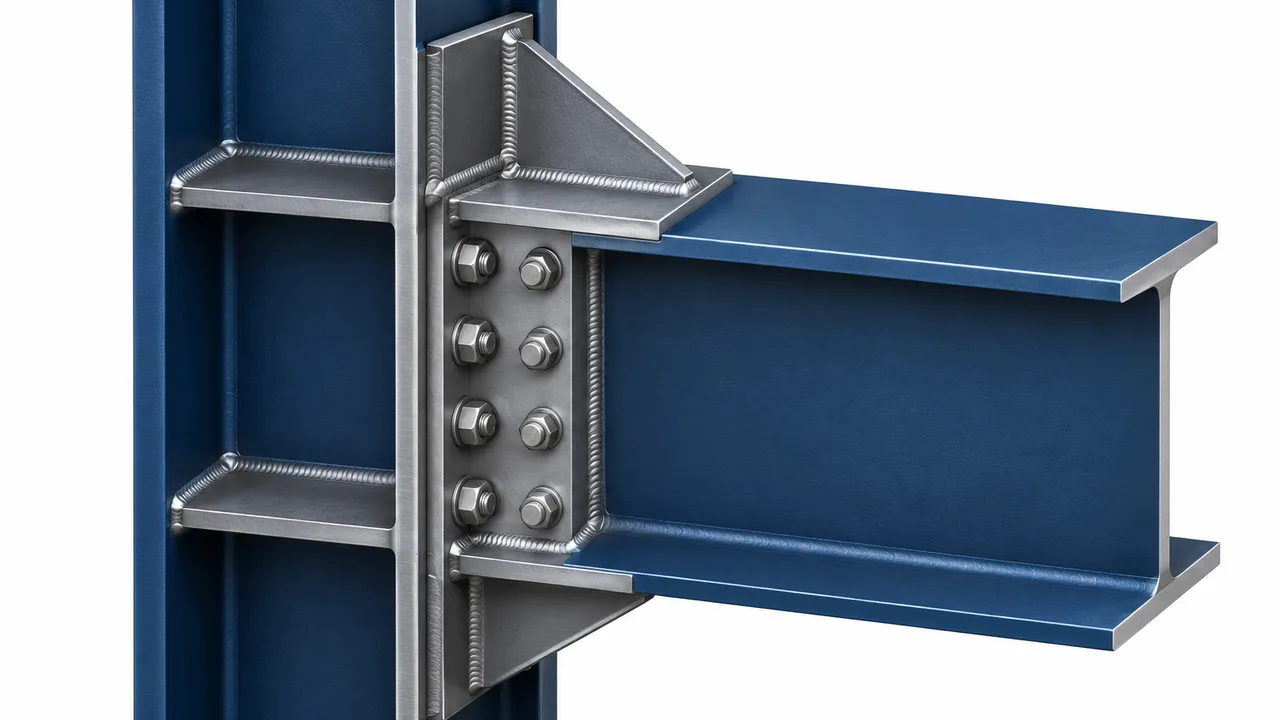
Connection performance depends not only on analytical capacity but also on how accurately the connection is fabricated and installed.
Bolt Installation and Pretension
Incorrect tightening can reduce slip resistance or create inconsistent load transfer between bolts.
Hole Alignment and Tolerances
Misaligned bolt holes may cause installation difficulties, unintended bearing, forced fit-up, or local stresses.
Weld Quality and Defects
Undersized welds, incomplete fusion, cracking, porosity, poor termination, and other defects can reduce available weld capacity.
Plate Fit-Up
Poor fit-up can introduce gaps or unintended eccentricity before the connection is even loaded.
Residual Stresses and Distortion
Welding heat can create distortion and residual stress that influence connection geometry and local behavior.
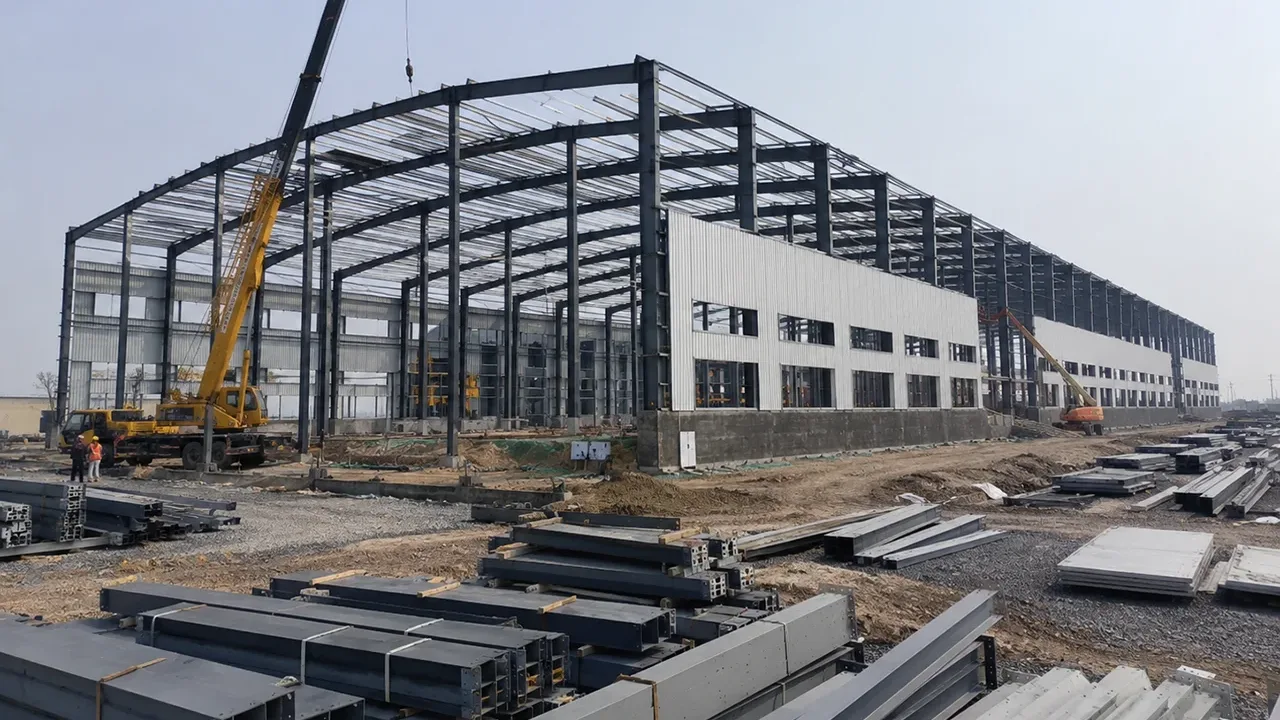
Controlled fabrication in a Steel structure factory can improve dimensional accuracy, weld consistency, bolt-hole alignment, inspection quality, and repeatability before components are delivered to the construction site.
Common Steel Connection Design Mistakes
Many connection problems occur because only the most obvious component is checked.
Common mistakes include:
- Checking bolt strength but ignoring the connected plate
- Checking weld strength but ignoring base-metal failure
- Ignoring failure of the supporting member
- Ignoring web local yielding
- Ignoring web crippling or web buckling
- Failing to check block shear
- Ignoring prying action
- Using an incorrect effective weld length
- Providing insufficient bolt edge distance
- Using inadequate bolt spacing
- Ignoring connection eccentricity
- Assuming equal force distribution through all fasteners
- Ignoring excessive connection deformation
- Checking load effects independently when combined interaction governs
- Adding stiffeners without checking stiffener strength or buckling
A strong bolt or large weld does not guarantee a strong connection if another part of the load path has lower resistance.
How to Improve Steel Connection Capacity
The appropriate strengthening method depends on the governing limit state.
Increase Plate Thickness
Thicker plates can improve yielding, bearing, bending, and buckling resistance.
Add Stiffeners or Doubler Plates
Stiffeners and doubler plates can strengthen webs or flanges subjected to concentrated forces.
Increase Bolt Number or Diameter
Additional or larger bolts can reduce force per fastener, provided the surrounding plate and member also have sufficient capacity.
Increase Weld Size or Effective Length
Larger or longer welds can improve weld-group resistance when weld capacity controls.
Improve Bolt Layout
Increasing edge distance, bolt spacing, or bolt-group dimensions can improve bearing, tear-out, block shear, and moment resistance.
Reduce Load Eccentricity
Aligning the applied load more closely with the connection resistance line can reduce secondary moments.
Improve Load Distribution
Load spreaders, stiffeners, wider plates, or revised detailing can reduce local stress concentrations.
Select a More Suitable Connection Type
Sometimes modifying the connection concept is more efficient than strengthening every individual component of an unsuitable detail.
The safest and most efficient connection is one in which the entire load path has been evaluated as a coordinated system. By identifying the governing failure mechanism rather than concentrating on a single component, engineers can develop steel connections that provide predictable strength, suitable stiffness, and dependable structural performance.