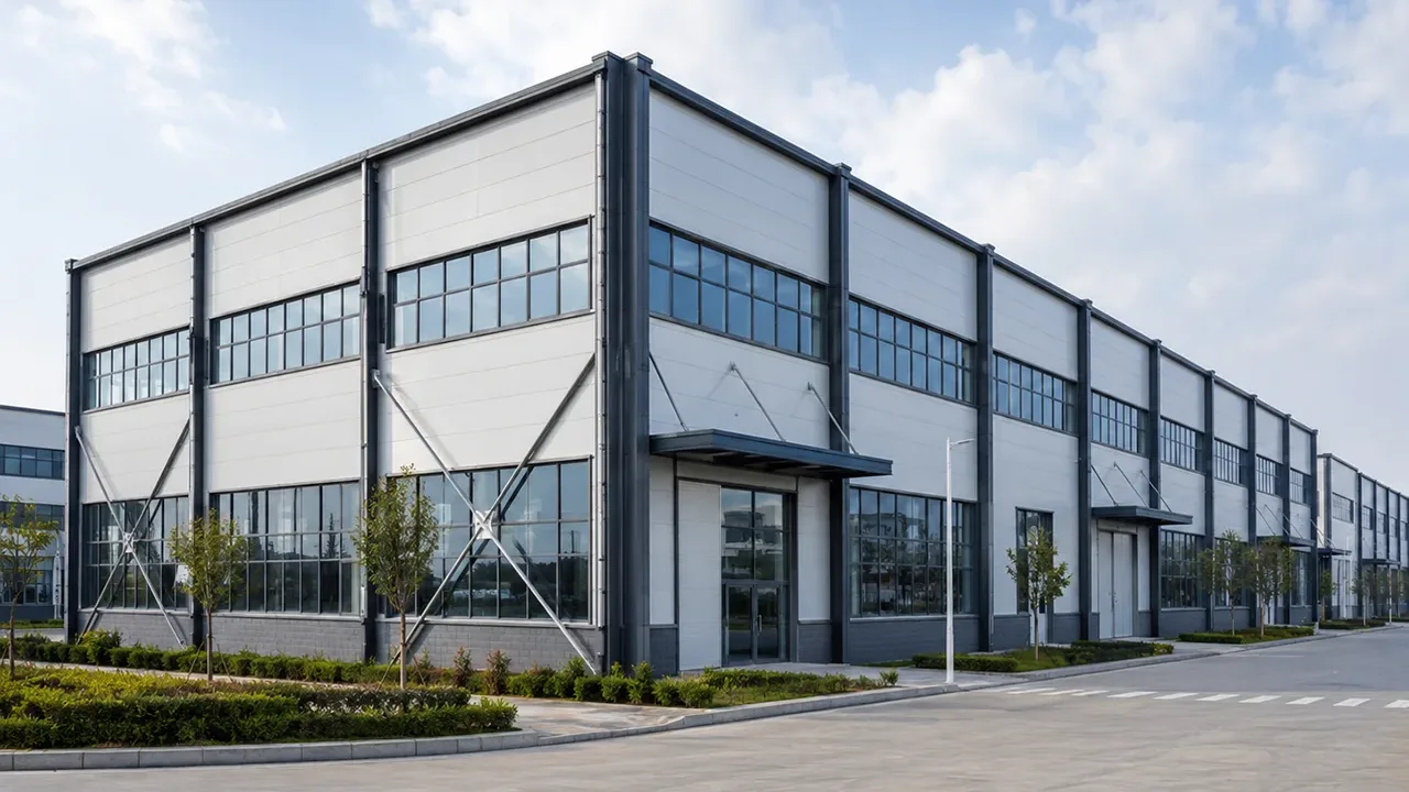
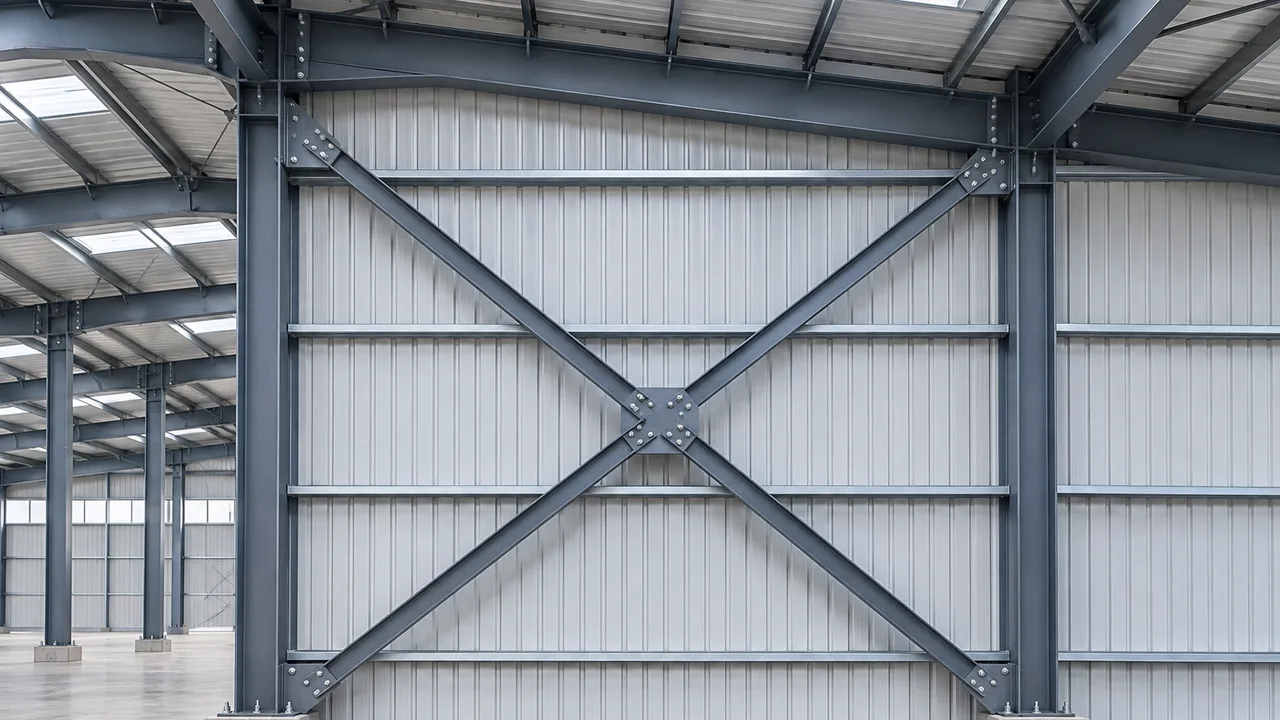
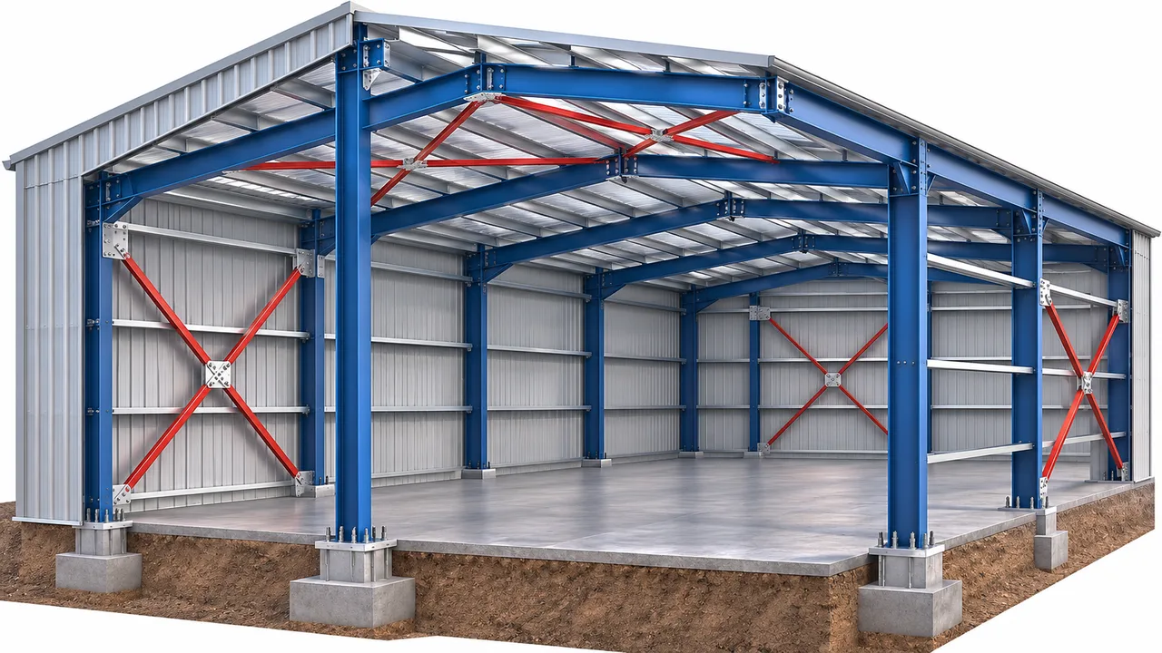
Cross bracing is one of the most widely used lateral stability systems in steel structures. Its characteristic X-shaped arrangement uses two diagonal members within the same structural bay to resist horizontal forces, control frame movement, and maintain the overall geometry of a building.
In warehouses, factories, workshops, industrial buildings, towers, and equipment support structures, cross bracing can provide an efficient path for wind, seismic, crane, and other lateral forces. Its effectiveness depends not only on the brace members themselves but also on their connections, gusset plates, supporting beams and columns, and the continuity of the complete load path.
Properly designed bracing helps reduce lateral displacement, stabilize structural frames, and transfer forces safely from the roof and walls into the foundations.
What Is Cross Bracing?
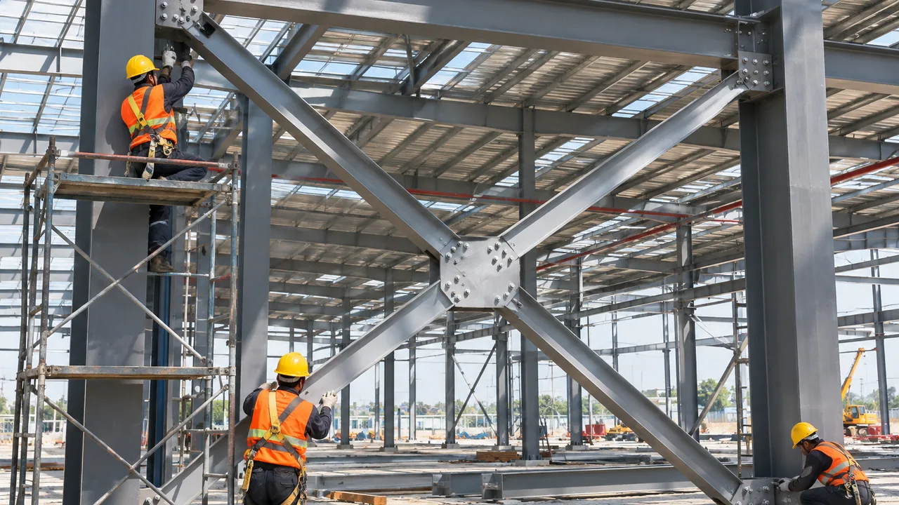
Cross bracing consists of two diagonal structural members that intersect within a frame bay, forming an X-shaped configuration.
Depending on the structural system, the braces may be fabricated from rods, angles, flat bars, hollow sections, channels, or heavier structural steel sections.
Basic Cross Bracing Configuration
A typical braced bay contains one diagonal running from the lower corner on one side to the upper corner on the opposite side, while the second brace runs in the reverse direction.
This arrangement allows the system to respond efficiently when lateral load direction changes.
How Cross Bracing Differs From a Single Diagonal Brace
A single diagonal bracing member provides lateral resistance in one diagonal direction, while an X-braced bay contains two intersecting diagonals.
The second brace can provide additional stiffness, improved response under load reversal, and greater flexibility in distributing lateral forces.
In tension-only systems, one diagonal may become active while the opposite member becomes less effective under compression. When the lateral force reverses direction, their roles can switch.
Where Cross Bracing Is Installed
Typical locations include:
- Longitudinal wall bays
- End walls
- Roof planes
- Vertical building frames
- Industrial towers
- Pipe racks
- Equipment support structures
The location of each braced bay must coordinate with the structural load path and architectural requirements.
Main Functions of Cross Bracing in Steel Structures
Resisting Lateral Loads
One of the primary functions of cross bracing is resisting lateral forces generated by wind, seismic action, equipment movement, crane operation, and other horizontal loads.
Instead of relying entirely on beam-column bending resistance, the braces transfer much of the lateral force through axial tension or compression.
Maintaining Structural Stability
Bracing helps prevent excessive frame sway and maintains the relative position of beams, columns, rafters, and other structural components.
This is particularly important in long steel buildings where unbraced frames could experience excessive longitudinal movement.
Transferring Loads to the Foundation
Cross bracing forms part of a complete load-transfer system.
Lateral forces collected by roof or wall systems are directed into braced bays, transferred through the diagonal members into columns, and ultimately carried through column bases into the foundations.
If this path is interrupted, strong brace members alone cannot provide reliable structural stability.
Reducing Frame Deformation
Because diagonal members primarily resist axial force, braced systems can provide relatively high lateral stiffness with an efficient use of steel.
Reduced displacement can improve both structural performance and serviceability.
Providing Temporary and Permanent Stability
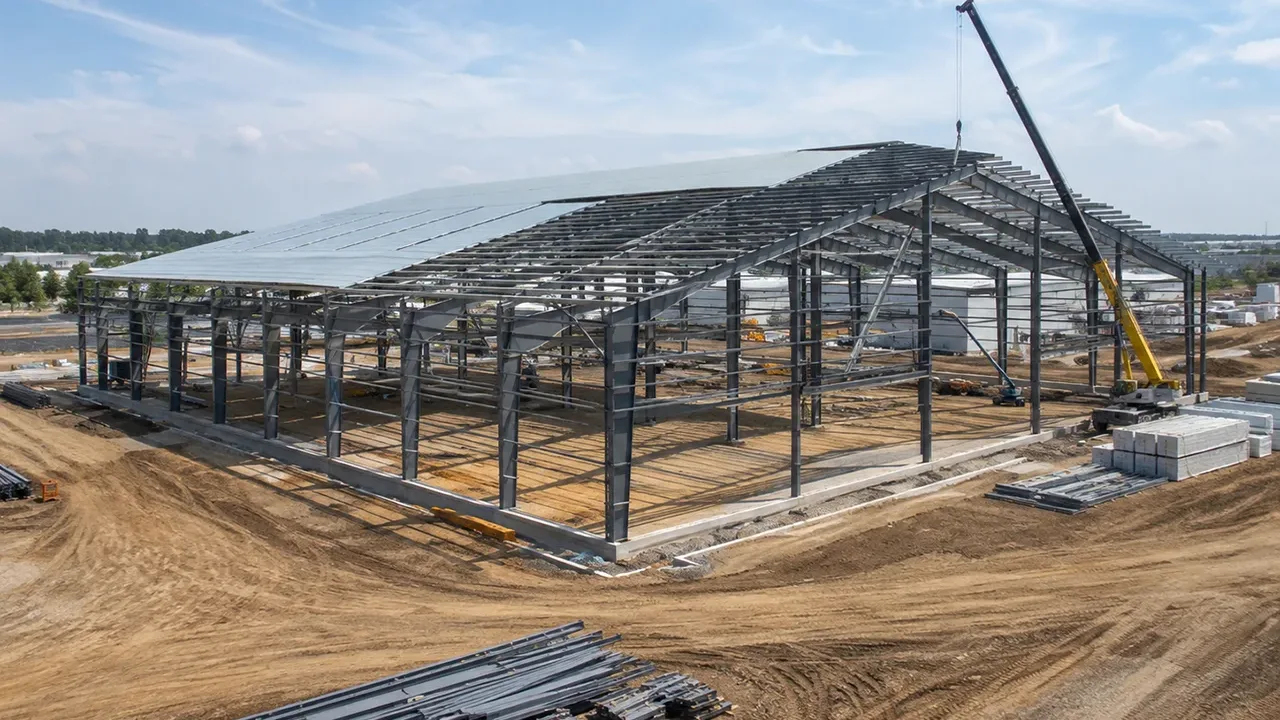
Bracing may also help stabilize the structure during erection before all permanent structural components are fully connected.
Temporary erection bracing and permanent design bracing should, however, be evaluated separately where required.
How Cross Bracing Works
Tension and Compression in Cross Braces
When a horizontal load acts on a braced bay, the diagonal members develop axial forces.
One brace may primarily resist tension, while the opposite diagonal may experience compression. The exact force distribution depends on member stiffness, connection detailing, geometry, and whether the system is designed as tension-only or tension-compression bracing.
Load Reversal Under Wind and Seismic Forces
Wind and seismic actions can reverse direction.
Under load reversal, a brace previously in tension may move into compression while the opposite brace becomes tensioned.
This makes the two-diagonal configuration particularly useful where lateral forces may act from either direction.
Tension-Only Cross Bracing Systems
Slender rods, cables, flat bars, or similar members are often treated primarily as tension elements.
When subjected to compression, these members may buckle or lose effectiveness. The opposite diagonal then provides the primary tension resistance.
Tension-Compression Cross Bracing Systems
More robust angles, hollow sections, channels, and structural sections may be designed to resist both tension and compression.
In these systems, brace slenderness and compression buckling capacity become critical design considerations.
Cross Bracing Load Path
The efficiency of a bracing system depends on the continuity of its load path.
From Roof and Wall Loads to the Braced Bay
Wind acting on cladding is first transferred into wall girts, roof purlins, diaphragms, or other secondary framing members.
These components direct the horizontal force toward designated braced bays.
Force Transfer Through Brace Members
The diagonal members convert much of the lateral loading into axial forces.
The brace section must have sufficient tensile or compressive resistance for the required design demand.
Brace-to-Gusset Plate Connections
Brace forces are commonly transferred through gusset plates using bolts, welds, or a combination of both.
The connection must resist the full brace force without premature yielding, fracture, block shear, or buckling.
Transfer Into Columns and Foundations
Forces from the gusset plates continue into columns, beams, or rafters and then through column bases into the foundation system.
Every component along this path must have sufficient resistance.
Types of Cross Bracing Members
Steel Rod Cross Bracing
Steel rods are lightweight and commonly used in tension-only bracing systems.
Turnbuckles or threaded adjustment systems can be used to control brace length and initial tension during installation.
Angle Cross Bracing
Steel angles are common in industrial structures because they are relatively simple to fabricate, connect, and install.
Depending on their slenderness, they may resist both tension and limited compression.
Flat Bar Cross Bracing
Flat bars provide a lightweight solution for smaller structures and wall or roof bracing applications.
Their compression resistance is generally limited because of their relatively low out-of-plane stiffness.
Hollow Section Cross Bracing
RHS, SHS, and CHS members provide better compression behavior and torsional stiffness than slender rods or flat bars.
They are often selected where both tension and compression resistance are required.
Channel and Structural Section Bracing
Channels and larger structural sections may be used in heavy industrial structures where brace forces are high.
These sections can provide greater axial and buckling resistance but require heavier connections.
Cross Bracing in Wall Systems
Longitudinal Wall Bracing
In portal frame buildings, transverse frames often resist loads across the building width, while longitudinal wall bracing stabilizes the structure along its length.
Vertical X-bracing between columns provides a direct path for longitudinal forces.
End Wall Bracing
End walls may require bracing to transfer wind forces into roof bracing and longitudinal stability systems.
Bracing Around Doors and Openings
Large doors, loading bays, windows, and production openings can conflict with diagonal members.
Designers may relocate bracing to adjacent bays or use an alternative lateral system where access must remain unobstructed.
Cross Bracing in Multi-Bay Buildings
Bracing does not necessarily need to be placed in every bay.
Strategically located braced bays can collect and transfer lateral forces efficiently when the surrounding structural system provides adequate load distribution.
Cross Bracing in Roof Systems
Horizontal Roof Cross Bracing
Roof bracing stabilizes the roof plane and transfers longitudinal forces toward vertical wall bracing.
This is particularly important in long industrial buildings.
Roof Bracing Between Rafters or Trusses
Diagonal roof members can maintain alignment between rafters or trusses and provide restraint to selected compression components.
Relationship Between Roof and Wall Bracing
Roof and wall bracing should operate as a coordinated three-dimensional stability system.
Roof forces must have a clear path into vertical bracing and then into the foundations.
Cross Bracing in Portal Frame Buildings
Longitudinal Stability of Portal Frames
Rigid portal frames are commonly designed to resist transverse loads through frame action.
Longitudinal stability, however, often depends on roof and wall bracing systems.
Bracing Between Columns
Vertical bracing installed between columns transfers longitudinal forces and helps restrain column movement.
Roof Bracing Between Rafters
Roof bracing can collect longitudinal wind forces and direct them toward designated wall-braced bays.
Interaction With Purlins and Girts
Purlins and girts may contribute to load distribution and member restraint.
Their role should be clearly defined in the structural model and detailing rather than assumed without verification.
Cross Bracing in Industrial Buildings
Steel Warehouses
Warehouses often have long building lengths and repetitive portal frames. Bracing provides an economical method for controlling longitudinal movement and wind response.
Steel Factories
Factories may introduce additional forces from cranes, equipment, suspended services, or heavy production systems.
Bracing must be designed for the actual load combinations associated with these operations.
Workshops and Production Buildings
Workshops often require large doors and open production areas.
Braced bays therefore need careful coordination with access routes and equipment layouts.
Logistics and Storage Buildings
Long logistics facilities can use strategically distributed braced bays to provide stability while preserving functional loading and circulation areas.
Cross Bracing for Crane-Supported Structures
Longitudinal Crane Forces
Overhead cranes can generate horizontal forces through acceleration, braking, skewing, and operational movement.
These forces may be transferred through crane girders into columns and bracing systems.
Bracing Loads at Column Level
Vertical bracing may transfer longitudinal crane forces between columns and toward the foundation.
The connection between braces and columns must be designed for these concentrated demands.
Fatigue and Repeated Loading Considerations
Crane-supported structures may experience repeated loading cycles.
Where fatigue is relevant, brace details, welds, bolts, and connection geometry require additional attention.
Cross Bracing Under Wind Loads
Wind can create pressure, suction, uplift, and longitudinal forces throughout a steel building.
Bracing transfers these actions from roof and wall systems into stable structural lines.
Because wind direction can reverse, brace force direction may also reverse.
Adequate lateral stiffness helps control building drift, cladding deformation, and secondary structural movement.
Cross Bracing Under Seismic Loads
Seismic loading can subject braces to repeated cyclic force reversal.
A brace may alternate between tension and compression during an earthquake.
Compression members must therefore be evaluated for buckling, while connections and gusset plates require sufficient strength and deformation capacity.
Ordinary cross bracing should not automatically be assumed to provide code-compliant seismic resistance. Seismic braced frames may require specific member proportions, ductility provisions, connection detailing, and design procedures according to the applicable structural standard.
Benefits of Cross Bracing
Cross bracing offers several structural and construction advantages:
- High lateral stiffness
- Efficient axial load resistance
- Relatively simple structural behavior
- Efficient use of structural steel
- Resistance to lateral load reversal
- Compatibility with repetitive structural bays
- Suitable performance in warehouses and industrial buildings
- Relatively straightforward fabrication and installation
These advantages make it a common solution for both light and heavy steel structures.
Limitations of Cross Bracing
Bracing can also create practical limitations.
Diagonal members may interfere with doors, windows, machinery, circulation paths, loading docks, or architectural openings.
Compression braces may require larger sections to prevent buckling, while heavily loaded connections can create congestion around gusset plates.
Installation tolerances also become important because misaligned brace members can be difficult to connect without introducing unintended force or deformation.
Cross Bracing vs Other Bracing Systems
Cross Bracing vs Diagonal Bracing
Cross bracing uses two diagonals within the same bay, whereas a single diagonal system uses one primary brace.
X-bracing can offer improved behavior under force reversal but may require more material and occupy more of the bay.
Cross Bracing vs K-Bracing
K-bracing connects diagonal members to an intermediate location on the column.
This changes the force path and can introduce additional local forces into the column.
Cross Bracing vs V-Bracing
V-bracing or chevron bracing connects diagonal members to a common point on a beam.
This configuration can create significant vertical forces in the beam if brace forces become unbalanced.
Cross Bracing vs Moment-Resisting Frames
Moment frames provide open bays without diagonal members but generally rely more heavily on beam-column bending stiffness and stronger moment connections.
Braced frames can often provide greater lateral stiffness with less steel, although they restrict openings within braced bays.
Key Design Factors for Cross Bracing
The design of cross bracing should consider:
- Brace length
- Member slenderness
- Tension capacity
- Compression buckling capacity
- Effective length
- Steel grade
- Brace cross-section
- Design load combinations
- Connection eccentricity
- Expected load reversal
The governing design condition may be brace yielding, compression buckling, connection failure, or failure of the supporting structure.
Cross Bracing Connection Design
Gusset Plate Connections
Gusset plates provide a practical transition between braces and the primary frame.
They must transfer the brace force while resisting yielding, fracture, block shear, and buckling.
Bolted Cross Bracing Connections
Bolted connections may require checks for bolt shear, bolt bearing, edge tear-out, net-section fracture, and block shear.
Bolt spacing and edge distances should also satisfy the applicable detailing requirements.
Welded Cross Bracing Connections
Welded connections require sufficient weld size, effective length, and base-metal resistance.
Connection eccentricity should also be considered where the brace force does not align with the weld group centroid.
Brace Intersection Detail
The two diagonals do not always need to transfer force directly to each other at their crossing point.
Depending on the structural concept, they may cross independently or use plates, spacers, or other detailing to control geometry and interference.
Connection to Columns and Beams
Brace forces eventually enter primary beams, columns, or rafters.
These supporting components must be checked for local yielding, bending, shear, and other relevant limit states.
Gusset Plate Considerations for Cross Bracing
A gusset plate may fail even when the brace itself has adequate capacity.
Important checks include:
- Gross-section yielding
- Net-section fracture
- Block shear
- Gusset plate buckling
- Whitmore section capacity
- Bolt and weld resistance
- Connection eccentricity
Compression braces can place significant stability demands on gusset plates, particularly where the unsupported plate region is large.
Common Cross Bracing Failure Modes
Possible failure mechanisms include:
- Brace yielding in tension
- Brace buckling in compression
- Bolt shear or tension failure
- Bolt-hole bearing or tear-out
- Weld rupture
- Gusset plate yielding or fracture
- Gusset plate buckling
- Local failure of supporting beams or columns
A reliable design should evaluate the entire connection system rather than only the diagonal member.
How Cross Bracing Placement Affects Structural Performance
Braced Bay Location
Braced bays are often positioned near building ends or at selected intermediate locations.
Their spacing depends on building length, lateral loads, roof and wall load paths, and structural stiffness.
Symmetrical vs Asymmetrical Bracing Layout
A highly asymmetric bracing layout can create torsional response if the center of lateral resistance is significantly offset from the applied loading.
Continuous Vertical Load Path
In multi-level structures, bracing should generally maintain a clear vertical transfer path between floors and foundations.
Avoiding Discontinuous Bracing
Abrupt changes in brace location or stiffness can complicate force transfer and introduce concentrated demands into beams, collectors, or diaphragms.
Cross Bracing and Building Openings
Doors and large openings frequently compete with the ideal locations for structural bracing.
When a diagonal would obstruct an opening, designers may relocate the braced bay, modify the brace geometry, or use another lateral resistance system.
Moment-resisting frames may be used locally where completely open bays are necessary.
Structural and architectural coordination should therefore occur early in the design process.
Fabrication of Cross Bracing Components
Accurate fabrication is important because diagonal members must fit correctly between predetermined connection points.
Cutting and Hole Preparation
Brace length, end geometry, and bolt-hole positions must remain within fabrication tolerances.
Gusset Plate Fabrication
Gusset dimensions, hole patterns, plate thickness, and edge distances should match the structural design.
Welding Quality
Weld size, continuity, penetration where required, and defect control directly influence connection capacity.
Dimensional Accuracy
Small dimensional errors can become significant when a long diagonal member must connect between fixed frame points.
Trial Assembly and Fit-Up
For complex or heavily loaded structures, trial fit-up may help identify alignment issues before site erection.
Controlled fabrication in a Steel structure factory can improve brace dimensions, bolt-hole alignment, gusset plate geometry, welding quality, and installation accuracy before structural components arrive on site.
Installation of Cross Bracing
Brace Installation Sequence
The erection sequence should maintain frame stability while braces are installed progressively.
Temporary Stability During Erection
A partially erected steel frame may not yet have its permanent load paths fully established.
Temporary bracing may therefore be required until the permanent structural system becomes stable.
Bolt Tightening and Adjustment
Bolted brace connections should be aligned correctly before final tightening.
Forced alignment can introduce unintended deformation or residual forces.
Tensioning Rod Bracing
Rod bracing may use threaded ends or turnbuckles to adjust length and remove excessive slack.
Over-tensioning should also be avoided unless specifically required by the design.
Final Alignment and Inspection
After erection, brace alignment, bolts, welds, gusset plates, and overall frame geometry should be checked against the project requirements.
Common Cross Bracing Design and Installation Mistakes
Common problems include:
- Using strong braces without providing a complete load path
- Ignoring compression buckling
- Assuming both diagonals always carry equal force
- Using gusset plates with insufficient capacity
- Providing weak brace-to-frame connections
- Using inadequate bolt edge distances
- Using poor weld detailing
- Misaligning bolt holes during fabrication
- Interrupting bracing with building openings
- Using asymmetric bracing without checking torsional effects
- Providing inadequate temporary erection stability
- Ignoring lateral load reversal
- Creating excessive connection eccentricity
- Treating slender tension-only rods as reliable compression members
- Failing to coordinate roof and wall bracing systems
These errors can reduce the effectiveness of an otherwise adequate bracing concept.
How to Improve Cross Bracing Performance
Select the Appropriate Brace Section
Brace sections should be selected according to required tension capacity, compression capacity, slenderness, connection geometry, and construction requirements.
Reduce Brace Slenderness
Where compression resistance is important, reducing unsupported length or selecting a stiffer section can improve buckling capacity.
Strengthen Gusset Plates
Increasing plate thickness, improving edge geometry, or reducing unsupported plate dimensions can improve gusset performance.
Improve Connection Geometry
Connections should transfer brace forces as directly as practical while minimizing unnecessary local bending.
Reduce Eccentricity
Aligning brace forces with connection resistance lines can reduce secondary moments.
Optimize Braced Bay Locations
Braced bays should be positioned to provide efficient load paths without unnecessarily restricting building operation.
Coordinate Roof and Wall Bracing
Roof and wall systems should work together rather than behave as isolated bracing components.
Provide Proper Erection Stability
Temporary bracing and erection sequencing should maintain stability until the permanent system is complete.
Typical Applications of Cross Bracing
Cross bracing is commonly used in:
- Steel warehouses
- Steel factories
- Industrial workshops
- Manufacturing buildings
- Aircraft hangars
- Logistics facilities
- Pipe racks
- Equipment support structures
- Steel towers
- Industrial platforms
- Truss systems
- Multi-story steel frames
Its simple geometry and efficient axial force behavior make it suitable for a wide range of structural systems.
FAQ
What Is Cross Bracing in a Steel Structure?
Cross bracing is a lateral stability system consisting of two diagonal members that intersect within a structural bay to form an X-shaped configuration. The braces transfer horizontal forces primarily through axial tension or compression.
What Is the Main Purpose of Cross Bracing?
Its main purpose is to resist lateral loads, limit frame sway, maintain structural geometry, and transfer horizontal forces toward stable structural lines and foundations.
How Does Cross Bracing Resist Lateral Loads?
Lateral movement causes axial forces to develop in the diagonal members. Depending on the design, one brace may act mainly in tension while the other resists compression or becomes active when the load direction reverses.
Is Cross Bracing Better Than Diagonal Bracing?
Neither system is universally better. Cross bracing can provide greater stiffness and improved response to load reversal, while a single diagonal may use less material and create fewer obstructions. The appropriate system depends on structural and architectural requirements.
Can Cross Bracing Carry Compression?
Yes, when the brace member has sufficient compression and buckling resistance. Slender rods or flat bars, however, are often treated as tension-only elements because they can buckle easily under compression.
Where Should Cross Bracing Be Installed?
It may be installed in selected wall bays, roof planes, end walls, longitudinal frames, towers, and other locations that provide a continuous lateral load path to the foundation.
Why Are Gusset Plates Used With Cross Bracing?
Gusset plates connect diagonal braces to beams, columns, or other main structural members and distribute brace forces into the supporting frame.
Can Cross Bracing Be Used in Seismic Structures?
Yes, but seismic bracing requires appropriate code-based design and detailing. Brace slenderness, cyclic buckling, ductility, gusset plate behavior, and connection strength may all require special consideration.
Conclusion
Cross bracing provides an efficient method for improving the lateral stability of steel structures. By transferring wind, seismic, crane, and other horizontal forces through diagonal members, it can reduce frame movement and provide a clear path for lateral loads.
Its performance depends on more than the strength of the braces themselves. Brace slenderness, tension and compression resistance, gusset plate capacity, connection detailing, braced bay location, and coordination between roof and wall systems all influence the effectiveness of the complete system.
When these elements are designed as part of a continuous load path, cross-braced systems can provide reliable and economical stability for warehouses, factories, workshops, industrial buildings, towers, and many other steel structures.