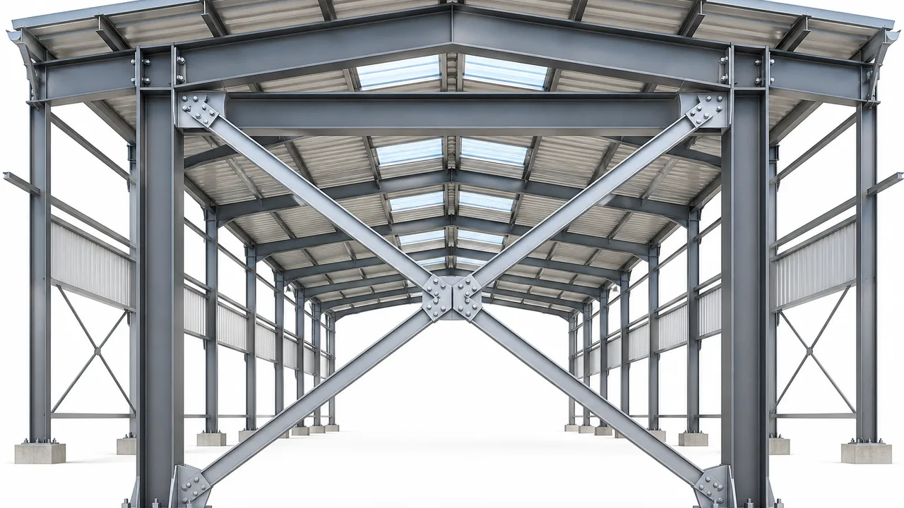
Lateral stability is essential in steel buildings exposed to wind, seismic forces, crane movement, equipment loads, and other horizontal actions. Among the most efficient systems used to control these forces is cross bracing in steel structures, where diagonal members form an X-shaped arrangement between columns, beams, or roof framing members.
This configuration creates a direct path for transferring horizontal loads through the structural frame and into the foundation. Because the diagonal members primarily resist axial forces, cross bracing can provide high lateral stiffness with relatively low steel consumption. It is widely used in warehouses, factories, workshops, hangars, industrial buildings, and other steel structures where strength, stability, and economical construction are important.
What Is Cross Bracing in Steel Structures?
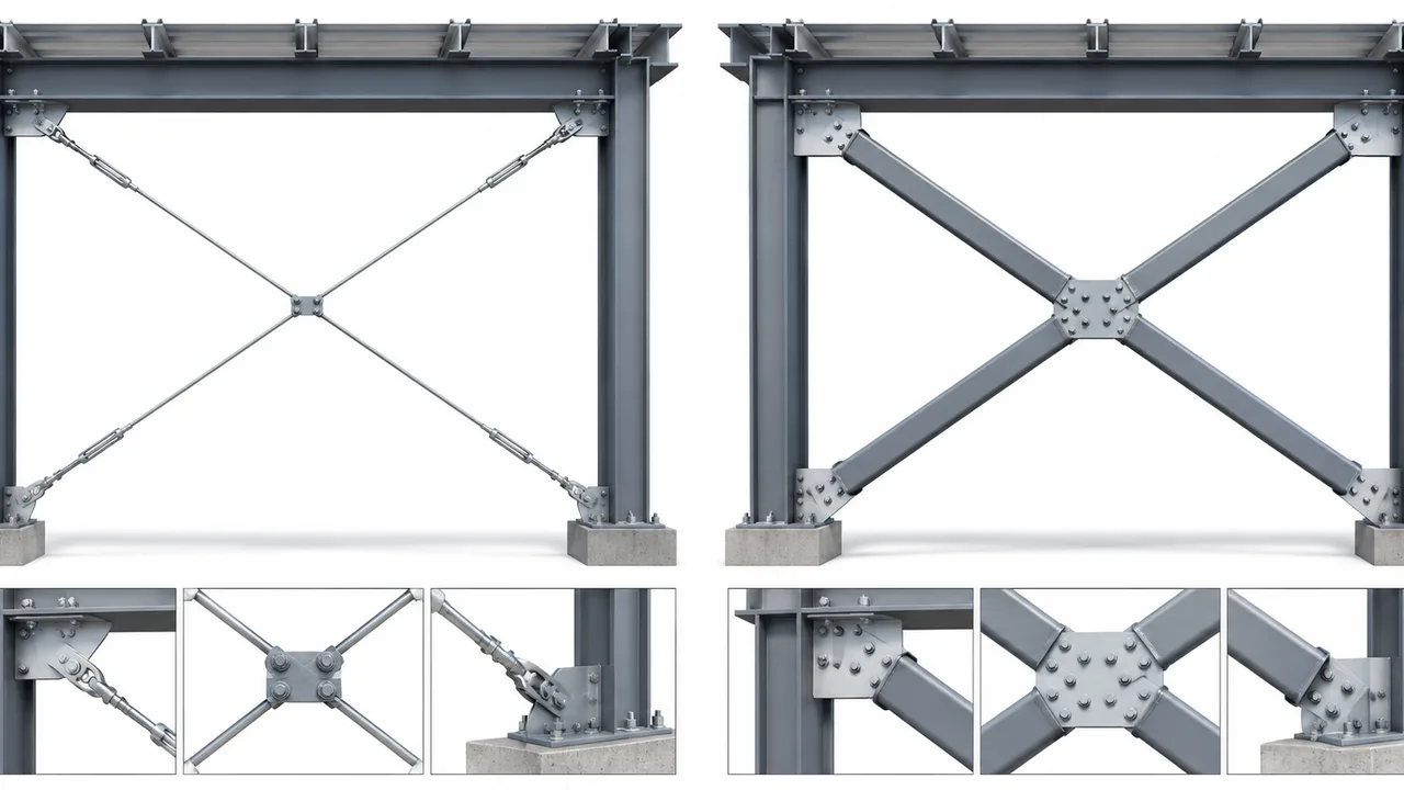
Cross bracing consists of two diagonal members installed across a structural bay so that they intersect and form an X configuration. Depending on the design, the diagonal members may resist tension only or a combination of tension and compression.
When a lateral load acts in one direction, one diagonal typically develops tension while the opposite diagonal may be subjected to compression. If the system uses slender rods or cables, the compression member may be neglected and the opposing diagonal becomes active when the direction of loading reverses. More robust sections such as angles, pipes, or hollow structural sections can be designed to resist both tension and compression.
The primary purpose of cross bracing in steel structures is to prevent excessive lateral displacement and maintain the geometry of the structural frame while providing an efficient load path between the roof, walls, columns, and foundations.
Why Cross Bracing Is Important for Lateral Stability
Resistance to Wind Loads
Wind pressure and suction can generate significant horizontal forces on the walls and roof of a steel building. Cross bracing collects these forces from the structural frame and transfers them toward the foundation. Without an adequate bracing system, the building may experience excessive sway, connection deformation, or instability.
Resistance to Seismic Loads
During an earthquake, lateral forces can reverse rapidly. Bracing members and their connections must therefore accommodate repeated changes in force direction. Properly designed cross bracing provides a defined lateral load-resisting system and helps control building displacement during seismic movement.
Controlling Frame Sway
Even when the structural members have sufficient individual strength, excessive frame movement can affect cladding, doors, windows, equipment, crane systems, and other building components. Bracing increases lateral stiffness and limits these movements.
Maintaining Structural Geometry
Cross bracing helps maintain the intended alignment of columns, beams, and roof framing. It is particularly important during erection, when the permanent structural system may not yet be fully connected.
How Cross Bracing Transfers Lateral Loads
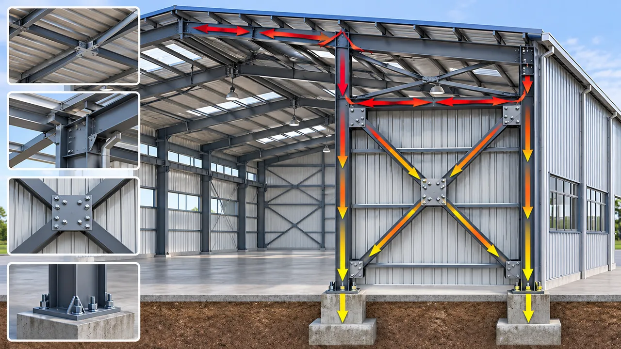
A properly designed bracing system must provide a continuous load path. Wind or seismic forces are first collected by roof and wall systems. These forces are transferred through purlins, girts, diaphragms, or structural frames toward designated braced bays.
The diagonal members then carry the resulting axial forces to columns and ultimately into the foundations. Connections between braces, gusset plates, beams, and columns must have enough capacity to transfer these forces without local failure.
The effectiveness of the system therefore depends not only on the diagonal brace itself but also on every component along the load path. Weak connections, insufficient gusset plates, or inadequate foundation reactions can limit the capacity of the entire system.
Main Components of a Cross Bracing System
Diagonal Bracing Members
Diagonal members are the primary force-resisting elements. Common sections include rods, angles, flat bars, channels, pipes, and hollow structural sections.
Gusset Plates
Gusset plates connect the braces to beams, columns, or other framing members. Their thickness, geometry, and connection arrangement must be checked for yielding, rupture, buckling, block shear, and local deformation.
Bolted and Welded Connections
Braces may be connected using bolts, welds, or a combination of both. Connection capacity should be compatible with the expected axial force in the brace.
Columns and Beams
Forces generated by the bracing system are transferred into surrounding beams and columns. These members must therefore be checked for the additional axial force, shear, bending, and connection effects introduced by the bracing system.
Foundation Connections
Bracing forces eventually reach the foundation. Base plates, anchor bolts, concrete foundations, and soil resistance must be capable of transferring the resulting tension, compression, and shear forces.
Common Cross Bracing Configurations
X-Bracing
X-bracing uses two diagonal members crossing within the same bay. It provides high stiffness and a direct load path, making it one of the most common configurations in industrial steel buildings.
Single Diagonal Bracing
A single diagonal uses one member between opposite corners of a bay. It requires the member to resist both load directions or relies on multiple braced bays arranged strategically throughout the structure.
Chevron Bracing
Chevron bracing uses two diagonal members meeting near the center of a beam. It can preserve openings near columns but introduces concentrated forces into the supporting beam.
Inverted V-Bracing
Inverted V-bracing has diagonals extending from the upper corners of the bay toward a common point below. Like conventional chevron systems, beam forces must be carefully evaluated.
K-Bracing
K-bracing connects diagonal members to intermediate points along columns. Although it may provide architectural flexibility, it can introduce significant bending into columns and is not suitable for every structural or seismic application.
Cross Bracing in Wall and Roof Systems
Wall Cross Bracing
Wall bracing is commonly installed between columns in selected longitudinal bays. It transfers horizontal forces from roof bracing and wall systems toward the foundation. The braced bays are normally distributed to create a clear and balanced lateral load path.
Roof Cross Bracing
Roof bracing stabilizes the roof plane and transfers longitudinal forces between frames. It is commonly installed between rafters or roof trusses and coordinated with wall bracing below.
Roof bracing and vertical bracing should function as one continuous system. If the roof bracing delivers forces to a location without adequate wall bracing below, the intended load path can be interrupted.
Cross Bracing Design Under Wind Loads
Wind design requires consideration of pressure, suction, building geometry, exposure, height, and structural direction. Lateral forces acting on sidewalls or end walls are distributed through the roof and wall framing before reaching the bracing system.
The designer must determine which braced bays participate in resisting the load and how forces are distributed between them. Concentrating all bracing in a single location can create excessive forces in members, connections, and foundations.
Serviceability is also important. A bracing system may have adequate ultimate strength while still allowing excessive lateral movement under normal wind conditions.
Cross Bracing Design Under Seismic Loads
Seismic loading differs from ordinary static loading because forces can reverse repeatedly. Braces may alternate between tension and compression, making ductility, member slenderness, connection detailing, and buckling resistance especially important.
Connections should be capable of transferring the expected cyclic forces without premature fracture. The designer must also evaluate how brace buckling or yielding affects the surrounding beams and columns.
For seismic applications, the behavior of the complete structural system is more important than the strength of an isolated diagonal member.
Tension-Only vs Tension-Compression Cross Bracing
Tension-Only Bracing
Slender rods, cables, or flat members are often designed to carry tension only. Under loading in one direction, one diagonal becomes active while the opposite diagonal becomes ineffective in compression. When the load reverses, their roles change.
This approach can be economical for light industrial buildings where high compression resistance is not required.
Tension-Compression Bracing
Angles, channels, pipes, and hollow sections can be designed to carry both tension and compression. These members generally provide greater stiffness but require careful evaluation of compression buckling and effective length.
Member Selection for Cross Bracing
Brace selection depends on axial force, unsupported length, connection configuration, corrosion environment, fabrication requirements, building use, and erection method.
Steel rods are economical for tension-only systems, while angles are widely used because they are simple to fabricate and connect. Hollow sections and pipes provide good compression behavior and torsional resistance, making them suitable for heavier structures. Flat bars can be practical for lighter applications but usually have limited compression capacity.
Member selection should therefore be based on both structural capacity and practical construction requirements.
Cross Bracing Connection Design
Gusset Plate Connections
Gusset plates distribute brace forces into beams and columns. Their geometry should provide a clear load path while limiting excessive eccentricity.
Bolted Connections
Bolted connections must be checked for bolt shear, bolt tension when applicable, bearing, net-section rupture, block shear, and plate deformation.
Welded Connections
Welded brace connections require adequate weld size and effective length. The connected plate and supporting member must also have enough capacity to transfer the resulting forces.
Connection Eccentricity
If the brace force does not pass through the intended connection work point, secondary bending moments can develop. These effects may increase demand on gusset plates, bolts, welds, beams, or columns.
Net Section and Block Shear Checks
Bolt holes reduce the effective cross-sectional area of connected members. Net-section rupture and block shear must therefore be evaluated in addition to gross-section yielding.
Buckling and Slenderness in Cross Bracing
Compression braces can fail by buckling before the steel reaches its full compressive strength. The likelihood of buckling depends on member length, cross-sectional properties, end restraint, material strength, and effective length.
Slender members are particularly sensitive to out-of-plane instability. Connection details should not unintentionally create flexible end conditions that significantly increase the effective buckling length.
Where compression resistance is important, the designer may reduce unsupported length, increase the section size, select a more efficient section shape, or provide intermediate restraint.
Cross Bracing in Portal Frame Buildings
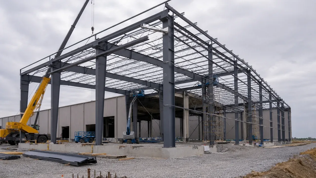
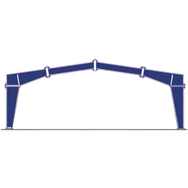
Portal frame warehouses, workshops, hangars, and industrial buildings frequently use cross bracing in the longitudinal direction. Portal frames primarily resist transverse loads, while longitudinal wall and roof bracing stabilize the building along its length.
Bracing is often located near end bays, although intermediate braced bays may be required in long buildings. Door openings, loading bays, production lines, crane systems, and expansion joints can influence the final bracing layout.
Proper coordination between portal frames, roof bracing, wall bracing, and foundations allows the complete building to behave as an integrated structural system.
Cross Bracing in Industrial Steel Buildings
Industrial buildings may experience lateral forces from bridge cranes, machinery, conveyors, wind, seismic actions, and operational movement. These loads can make bracing requirements more demanding than those of simple storage buildings.
In a large Steel structure factory, braced bays may also need to accommodate crane columns, high-clearance doors, production equipment, pipe racks, mezzanines, and other structural systems.
XTD Steel Structure considers these interactions during structural planning so that the bracing layout supports both lateral stability and the practical use of the industrial building.
Cross Bracing vs Other Bracing Systems
Cross Bracing vs Diagonal Bracing
Cross bracing generally offers greater redundancy and can provide resistance in both lateral directions. Single diagonal bracing uses fewer members but may require larger sections or additional braced bays.
Cross Bracing vs Portal Bracing
Portal bracing can preserve large openings for doors, vehicles, or production access. However, it typically requires stronger beams, columns, and moment connections than conventional X-bracing.
Cross Bracing vs Chevron Bracing
Chevron bracing provides useful central openings but transfers unbalanced vertical forces into the supporting beam. Cross bracing usually provides a more direct diagonal load path.
Cross Bracing vs Moment-Resisting Frames
Moment frames rely on rigid beam-column connections instead of diagonal members. They offer greater architectural flexibility but may require heavier sections and more complex connection fabrication.
Advantages of Cross Bracing in Steel Structures
- High lateral stiffness with relatively efficient material use.
- Direct transfer of wind and seismic forces.
- Simple structural behavior that is easy to analyze.
- Compatibility with prefabricated steel construction.
- Relatively simple fabrication and erection.
- Suitable for long warehouses, factories, workshops, and industrial buildings.
- Flexible selection of tension-only or tension-compression members.
These characteristics make cross bracing in steel structures particularly attractive when architectural openings do not prevent diagonal members from passing through the braced bay.
Limitations of Cross Bracing
Cross bracing is not suitable for every bay. Diagonal members can interfere with doors, windows, loading docks, vehicle access, equipment, conveyors, and production routes.
Compression diagonals can also become inefficient when members are extremely slender. In heavy structures, the intersection of multiple braces, gusset plates, bolts, and surrounding framing can create connection congestion.
For these reasons, bracing location should be coordinated early with architectural, mechanical, production, and access requirements.
Common Cross Bracing Design Mistakes
- Checking brace tension capacity while ignoring compression buckling.
- Using gusset plates that are too thin for the transferred forces.
- Providing insufficient bolt or weld capacity.
- Creating an incomplete load path between roof bracing and foundations.
- Ignoring connection eccentricity and secondary moments.
- Locating braced bays without considering force distribution.
- Ignoring forces transferred into adjacent beams and columns.
- Failing to verify anchor bolts and foundation reactions.
- Removing bracing during construction without temporary stabilization.
- Allowing architectural changes to interrupt the intended bracing system.
Cross Bracing Design and Capacity Check Process
- Determine wind, seismic, crane, and other relevant lateral loads.
- Define the complete lateral load path through the building.
- Select appropriate wall and roof braced bays.
- Calculate forces transferred into each bracing system.
- Determine axial forces in the diagonal members.
- Select preliminary brace sections.
- Check gross-section tensile yielding.
- Check net-section tensile rupture.
- Check compression buckling where applicable.
- Verify member slenderness and effective length.
- Check gusset plate yielding and rupture.
- Check bolt shear, bearing, and tension where applicable.
- Check weld capacity for welded connections.
- Verify block shear and net-section capacity.
- Evaluate connection eccentricity and secondary forces.
- Check forces introduced into beams and columns.
- Verify anchor bolts, base plates, and foundation reactions.
- Check lateral drift and serviceability.
- Review temporary stability during erection.
- Finalize fabrication and connection details.
How to Improve Cross Bracing Performance
Increase Bracing Member Area
A larger member area can improve tensile capacity and, depending on the section geometry, increase compression resistance.
Reduce Unsupported Length
Shortening the effective length of a compression brace can significantly improve buckling capacity.
Use More Efficient Bracing Sections
Replacing slender flat members with angles, pipes, or hollow structural sections can improve compression and out-of-plane stability.
Strengthen Gusset Plates
Increasing gusset plate thickness or improving its geometry can reduce local yielding, buckling, and connection deformation.
Improve Connection Detailing
Proper bolt spacing, weld arrangement, edge distance, and connection geometry help ensure that the brace force is transferred efficiently.
Optimize Bracing Bay Locations
Distributing braced bays strategically can reduce excessive force concentrations and improve the overall stiffness of the building.
Reduce Connection Eccentricity
Aligning brace forces with the intended work points of beams and columns minimizes unnecessary secondary bending.
Choosing the Right Cross Bracing System
The most appropriate bracing configuration depends on building geometry, lateral load magnitude, structural height, bay spacing, required openings, member slenderness, connection capacity, fabrication methods, and erection requirements. A system that works efficiently in a warehouse may not be suitable for a crane-supported factory or a building with large access openings.
Effective cross bracing in steel structures should therefore be designed as part of the complete lateral load-resisting system rather than treated as an isolated set of diagonal members. When the roof bracing, wall bracing, beams, columns, connections, and foundations are coordinated as one continuous load path, the structure can achieve predictable strength, suitable stiffness, and reliable long-term stability.