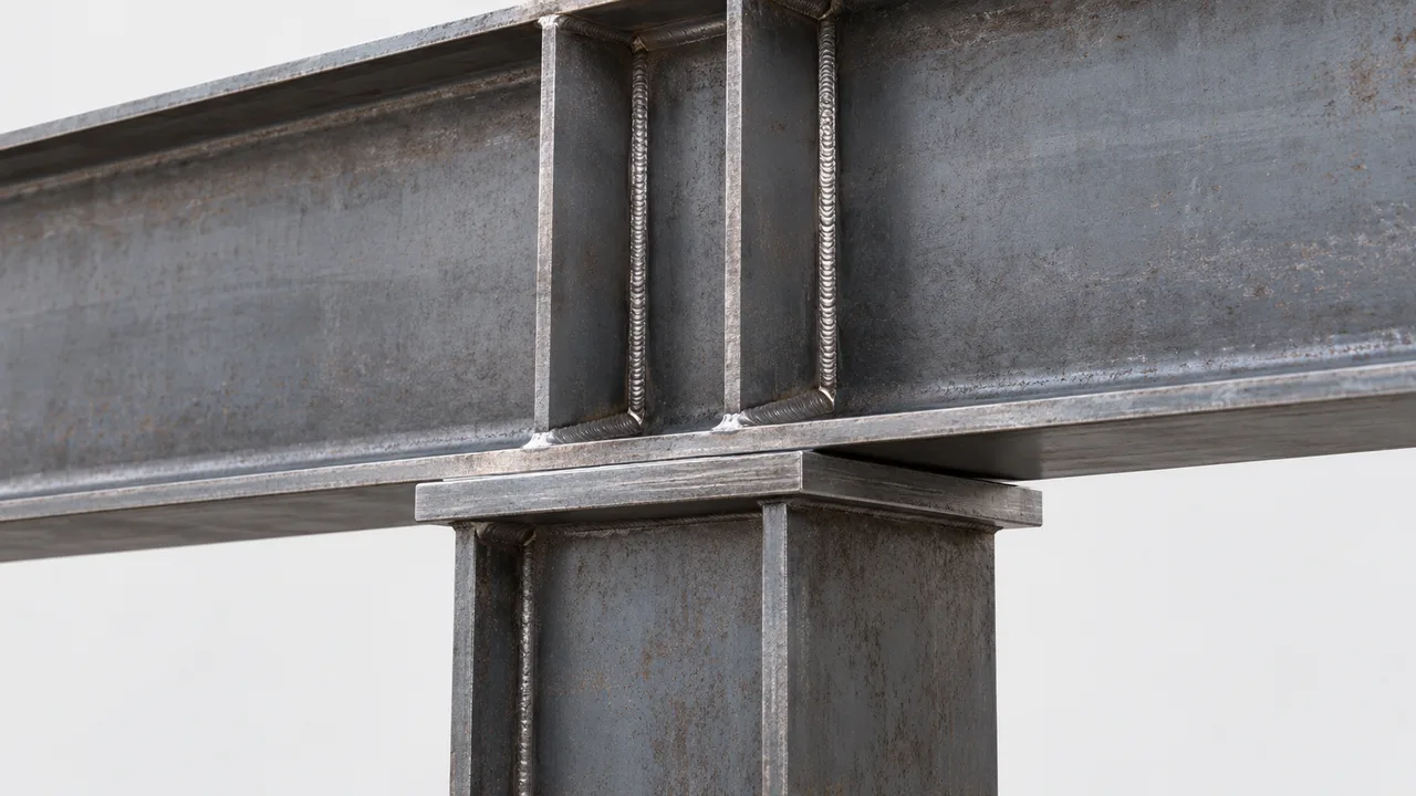
Large support reactions can create severe localized compression in the web region of a steel beam or girder. When the web alone cannot safely transfer that force, bearing stiffeners are commonly introduced to provide a stronger and more direct load path between the loaded flange, web, and supporting element. However, adding a stiffener does not automatically eliminate instability. The stiffener itself must remain stable while carrying compression.
Bearing stiffener buckling occurs when a support stiffener, often acting together with an effective portion of the beam web, becomes unstable under compressive loading before the intended resistance of the section is reached. This behavior is particularly important in transfer girders, crane girders, long-span beams, heavily loaded industrial structures, and other members where concentrated reactions are transferred through relatively small bearing zones.
A reliable design therefore requires more than checking the plate area or material yield strength. Engineers need to consider stiffener slenderness, effective length, web participation, connection restraint, load eccentricity, fabrication tolerances, and the interaction between the stiffener and surrounding beam components.
Why Bearing Stiffeners Are Used at Beam Supports
At a beam support, the vertical reaction must pass from the member into the supporting column, wall, bearing plate, bracket, or other structural element. When the reaction is moderate and the beam web is sufficiently strong, the web may transfer this force without additional reinforcement. For higher reactions, however, local web limit states can become critical.
Bearing stiffeners reinforce this region by providing additional compression area and improving the load path. They are frequently used at beam ends, girder supports, transfer points, crane runway supports, heavily loaded connections, and locations where equipment or framing produces significant concentrated forces.
The stiffener may be installed on one side of the web or on both sides, depending on the structural demand and detailing requirements. In high-load applications, paired stiffeners are often preferred because they provide a more symmetrical compression path and reduce eccentric behavior.
Load Transfer Through the Flange, Web, and Stiffener
The support reaction does not act on the stiffener in isolation. Force is transferred through a combination of the beam flange, web, stiffener plates, welds, and the supporting surface. The exact load path depends on the connection geometry and design assumptions.
Conceptually, the reaction can be considered as passing through the loaded flange into a stiffened web region and then into the support. As the compressive force increases, the bearing stiffener can behave similarly to a short compression member. If its effective compression section is too slender or inadequately restrained, bearing stiffener buckling can govern even when the steel has not reached its yield strength.
What Is Bearing Stiffener Buckling?
Bearing stiffener buckling is a stability failure in which a stiffener subjected to concentrated compression develops excessive lateral or out-of-plane deformation. Instead of failing because the steel reaches its material strength, the stiffener loses stability as a compression element.
The effective compression member may include both the stiffener plate and a portion of the adjacent beam web, depending on the design method and applicable structural standard. For this reason, the behavior should not normally be evaluated by considering only the isolated stiffener plate.
This distinction is important. A stiffener can have sufficient cross-sectional area to resist yielding while still having inadequate buckling resistance because of excessive slenderness, insufficient restraint, imperfect load alignment, or unfavorable end conditions.
How Buckling Develops in a Beam Support Area
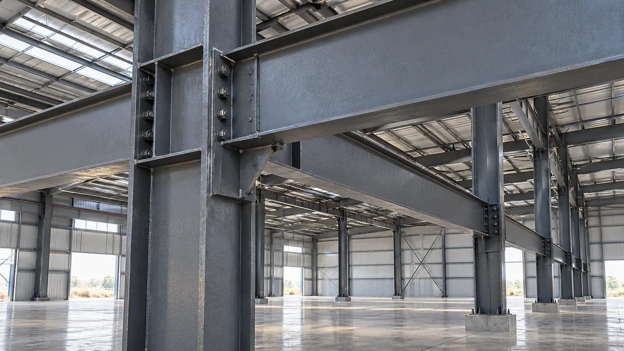
Concentrated Compression at the Support
Support regions are subjected to concentrated reaction forces rather than uniformly distributed compression. When a high reaction is introduced over a relatively short bearing length, stresses around the flange-web junction can become severe. The bearing stiffener provides an additional path for this force, but that also means the stiffener is subjected to substantial axial compression.
The higher the reaction relative to the stiffness of the support region, the more important stability becomes. This is one reason heavily loaded girders require careful checks even when the stiffener appears visually substantial.
Out-of-Plane Deformation of the Stiffener
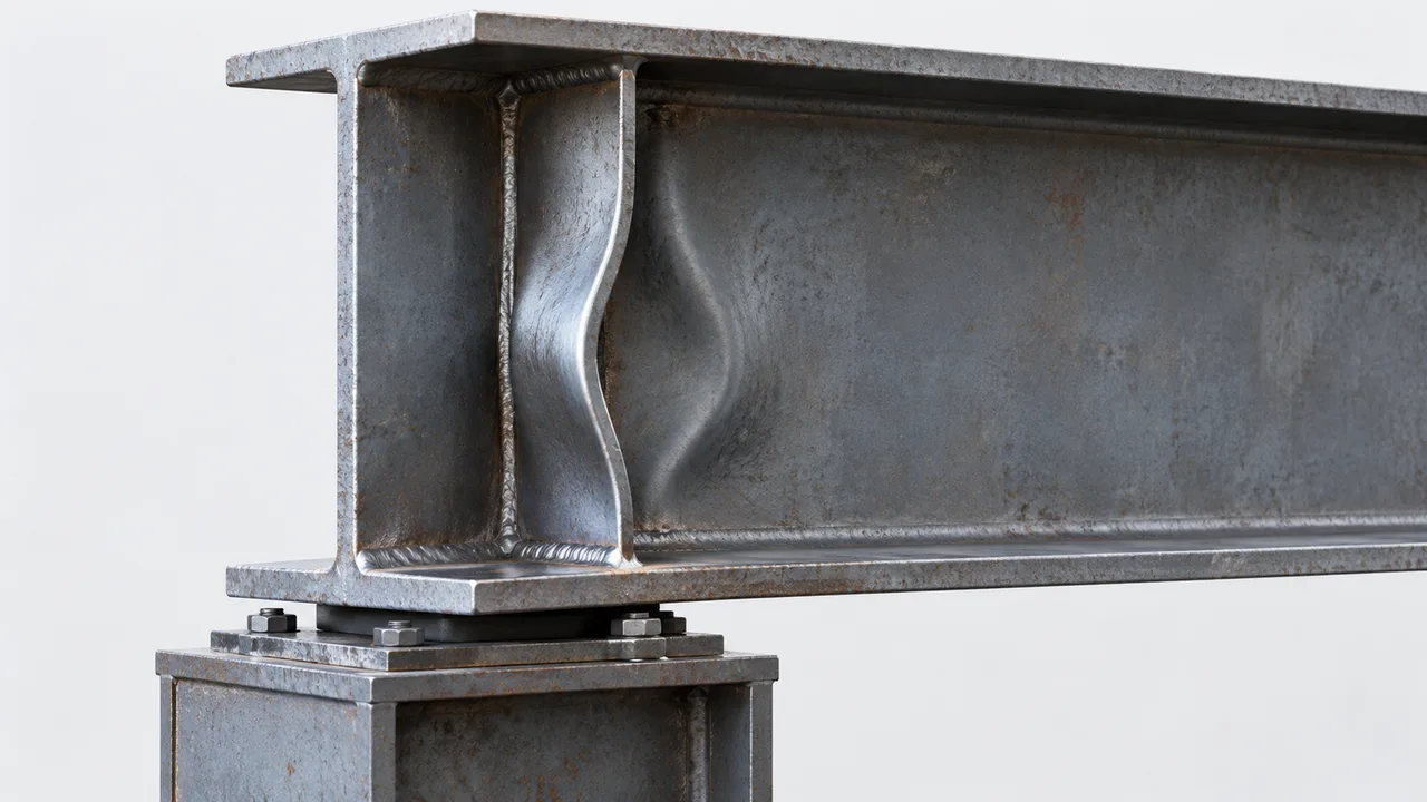
Real steel plates are never perfectly straight. Initial plate imperfections, welding distortion, residual stresses, uneven bearing, and small construction tolerances can introduce lateral deformation before the full design load is applied.
As compression increases, these imperfections can produce secondary bending in the stiffener. A relatively thin or long stiffener may progressively deflect out of plane until its compression resistance is controlled by buckling rather than yielding.
Interaction With Web Deformation
The beam web also contributes to support-region behavior. Local web deformation can change the restraint available to the stiffener, while stiffener deformation can modify the stress distribution within the web.
In practice, flange rotation, web distortion, stiffener bending, plate buckling, weld flexibility, and load eccentricity may occur simultaneously. The support region should therefore be treated as an interacting structural system rather than a collection of independent plates.
Bearing Stiffener Buckling vs Other Local Failure Modes
Several failure modes can develop around concentrated beam reactions. They may occur in the same physical region, but their structural mechanisms are different.
| Failure Mode | Main Mechanism | Typical Location | Main Design Concern |
|---|---|---|---|
| Bearing stiffener buckling | Compression instability of the stiffener system | Support stiffener region | Slenderness, effective length, and restraint |
| Stiffener yielding | Compression stress reaches material resistance | Stiffener and effective compression section | Effective area and steel strength |
| Web local yielding | Localized yielding under concentrated force | Web adjacent to the loaded flange | Bearing length, web thickness, and material strength |
| Web crippling | Localized web instability and deformation | Near concentrated loads or reactions | Web slenderness, geometry, and loading condition |
| Web buckling | Instability of a web panel or compression zone | Web panel around the support region | Web slenderness and boundary restraint |
A broader review of stiffener buckling is useful when comparing support-area instability with other plate and stiffener stability problems. For a beam support, however, the designer must evaluate all applicable web and stiffener limit states rather than assuming that one check automatically covers the others.
Key Factors That Control Bearing Stiffener Stability
Stiffener Plate Slenderness
Plate thickness and width strongly influence stability. A thin stiffener may provide enough nominal area for a yielding calculation but still have insufficient stiffness against out-of-plane deformation.
Local plate slenderness should therefore be considered together with the overall stability of the effective stiffener section. Increasing thickness can improve both local and overall resistance, although it is not always the most efficient solution.
Effective Stiffener Length
The relevant buckling length depends on how the stiffener is restrained by the beam flanges, web, welds, and surrounding connection. It should not automatically be assumed to equal the clear web depth or physical plate height.
Different support and connection arrangements can produce different effective boundary conditions. An incorrect effective-length assumption can significantly overestimate the available buckling resistance.
Web Contribution to the Effective Section
Many design approaches allow part of the beam web to participate with the stiffener when determining compression resistance. This creates an effective section that is wider and often more stable than the stiffener plate alone.
The amount of participating web should be determined in accordance with the selected structural design standard rather than chosen arbitrarily. Applicable requirements may be reviewed through resources such as the AISC Specification for Structural Steel Buildings for projects designed under the AISC system.
End Restraint From Beam Flanges
Stiffener stability depends heavily on restraint at its ends. A stiffener that is properly fitted, connected, and restrained against rotation behaves differently from a plate with incomplete contact or flexible end conditions.
The designer should verify how compression enters and leaves the stiffener and whether the actual fabrication detail provides the restraint assumed in structural calculations.
Load Eccentricity
Ideal calculations may assume that the reaction passes through the centroid of the effective stiffener section. Actual structures can introduce eccentricity through bearing plate location, connection geometry, offset supports, dimensional tolerances, or uneven fit-up.
Eccentric compression generates additional bending. Even relatively small eccentricity can become important for slender stiffeners and may accelerate bearing stiffener buckling.
Design Checks for Bearing Stiffener Buckling
A support stiffener should not be treated simply as a plate with an adequate cross-sectional area. A stability-based design process normally considers the design reaction, effective compression section, slenderness, buckling resistance, and actual restraint conditions.
Determine the Design Support Reaction
The first step is to establish the governing support reaction using the appropriate load combinations. Permanent loads, imposed loads, equipment loads, crane actions, environmental loads, construction conditions, and other relevant effects should be included where applicable.
For industrial structures, transient or repeated concentrated loads may also influence the governing design condition. The reaction used for stiffener design must be consistent with the overall structural analysis.
Establish the Effective Compression Section
The effective section may consist of one or more stiffener plates together with an allowed portion of the beam web. Its geometry affects both compression area and radius of gyration.
Single-sided stiffeners require particular attention because the resulting effective section may be asymmetric. Double-sided stiffeners generally provide a more balanced configuration, although the final arrangement should be selected based on calculated demand rather than symmetry alone.
Calculate Slenderness
Compression-member stability is strongly related to slenderness. In conceptual form, a slenderness parameter can be expressed using:
λ = KL / r
where K represents an effective-length factor, L represents the relevant unsupported or effective length, and r represents the radius of gyration of the effective compression section about the governing axis.
The applicable design standard determines how these quantities should be established and how the resulting slenderness is used in resistance calculations.
Determine Buckling Resistance
Once the effective section and slenderness are known, the available compression resistance can be determined using the buckling provisions of the selected design standard. Depending on slenderness, material strength, and section characteristics, the stiffener may behave in a relatively stocky or more instability-sensitive range.
This check is central to controlling bearing stiffener buckling. A high steel yield strength alone does not guarantee high compression resistance if the effective stiffener section is slender.
Compare Resistance With Applied Compression
The final verification should demonstrate that the design compression resistance of the effective stiffener system is not less than the required compressive force transferred through the support region.
This check should be coordinated with web yielding, web crippling, shear, weld, flange, bearing, and connection checks. Strengthening one component can simply shift the governing failure mode to another part of the support region.
Single-Sided vs Double-Sided Bearing Stiffeners
Single-Sided Stiffeners
A single stiffener plate may be suitable when reactions are moderate and the resulting eccentricity, local plate behavior, weld demand, and compression resistance have all been verified. The arrangement can reduce material and fabrication work, particularly where access to one side of the web is restricted.
Its asymmetric geometry, however, can make load transfer and out-of-plane behavior more sensitive to eccentricity. Designers should avoid selecting a single-sided configuration purely for fabrication convenience.
Double-Sided Stiffeners
Paired stiffeners create a more symmetrical compression zone and are commonly used for heavily loaded girders. They can improve stability, distribute force more evenly around the web, and provide a clearer load path between the flanges and support.
The additional plate and welding increase fabrication cost, so the most appropriate arrangement depends on reaction magnitude, beam geometry, connection requirements, fabrication access, and calculated bearing stiffener buckling resistance.
Connection Details That Affect Buckling Resistance
Stiffener-to-Web Welds
Welds connecting the stiffener to the web must transfer the required forces while maintaining the intended structural behavior. Inadequate weld size, discontinuities, excessive gaps, or incorrect weld layouts can prevent the stiffener and web from behaving as assumed.
Weld design should be coordinated with both strength requirements and practical fabrication procedures. Excessive welding should also be avoided where it unnecessarily increases heat input and distortion.
Stiffener-to-Flange Connection
The relationship between the stiffener and beam flange is particularly important because this region often controls how concentrated force enters the stiffener. Depending on the design concept, force may be transferred through direct bearing, welding, or a combination of contact and connection forces.
The fabricated detail should match the assumptions used by the engineer. A calculated compression member with strong end restraint may not behave as intended if the actual stiffener has poor flange contact or inadequate attachment.
Stiffener Fit-Up and Bearing
Small fabrication gaps can create significant local effects in heavily loaded support areas. If a bearing stiffener intended to transfer compression through direct contact does not fit properly against the flange, the force may initially be transferred through welds or local deformation instead.
This can introduce eccentricity and secondary bending that were not included in the original model. Accurate cutting, positioning, fit-up, and inspection are therefore part of controlling bearing stiffener buckling, not merely fabrication quality issues.
Common Causes of Bearing Stiffener Buckling
Several design and fabrication conditions can reduce the stability of a support stiffener:
- Using a stiffener plate that is too thin for the required compression force.
- Underestimating the effective unsupported length of the stiffener.
- Assuming stronger flange restraint than the connection actually provides.
- Applying a large concentrated reaction over a small support area.
- Introducing eccentricity between the reaction and effective stiffener section.
- Incorrectly estimating the amount of beam web participating in compression resistance.
- Providing inadequate stiffener-to-web or stiffener-to-flange connections.
- Allowing excessive welding distortion or plate out-of-flatness.
- Installing stiffeners outside the intended support centerline.
- Increasing operational loads without reassessing the original support design.
Because several of these conditions can occur simultaneously, investigations of bearing stiffener buckling should consider the entire support detail rather than checking plate thickness alone.
How Engineers Can Reduce Buckling Risk
Increase Stiffener Thickness
A thicker plate generally improves stiffness and reduces slenderness. This is one of the most direct ways to increase stability, but additional material may be unnecessary if the real problem is poor restraint, excessive effective length, or eccentric loading.
Use Stiffeners on Both Sides of the Web
For high reactions, paired stiffeners can provide better symmetry and reduce eccentric compression. They also create a larger effective compression section and may improve resistance about the critical buckling axis.
Improve Flange Restraint and Bearing Contact
Proper detailing at the stiffener ends helps establish the intended load path and effective-length condition. Where direct bearing is assumed, fit-up requirements should be clearly communicated to the fabrication team.
Reduce Effective Unsupported Length
Changes in geometry or restraint can sometimes provide a more efficient improvement than simply increasing plate thickness. Any modification should be supported by a structural model that represents the actual boundary conditions.
Improve Load Alignment
Support plates, stiffeners, reactions, and connection components should be arranged so that concentrated compression follows a direct and predictable path. Minimizing unnecessary eccentricity reduces secondary bending in the stiffener.
Verify Adjacent Web Limit States
Solving a stiffener stability problem does not automatically solve every support-region problem. Web local yielding, web crippling, shear interaction, flange behavior, weld resistance, and bearing conditions should also be verified.
Fabrication and Installation Issues That Can Reduce Capacity
The calculated resistance of a stiffened support region assumes that the fabricated member reasonably matches the structural drawings. Dimensional errors or welding distortion can alter the behavior of the compression system before the structure enters service.
Important fabrication controls include plate straightness, stiffener location, weld quality, flange contact, bearing surface preparation, dimensional tolerance, and control of heat-induced distortion. During erection, temporary loads and support conditions should also be considered because they may differ significantly from the final structural configuration.
For fabricated industrial steel structures, XTD Steel Structure coordinates detailing, steel processing, welding, dimensional control, and erection requirements so that heavily loaded stiffened members can be produced in accordance with the project design intent. This coordination is particularly important where large reactions leave little tolerance for misalignment or poor fit-up.
Bearing Stiffeners in Heavy Steel Structures
Industrial Buildings
Industrial buildings frequently contain transfer beams, equipment supports, pipe racks, platforms, and framing discontinuities that generate concentrated reactions. Bearing stiffeners can be required wherever these forces exceed the local capacity of the unstiffened beam web.
Crane Girders
Crane systems can introduce high wheel loads, repeated loading, impact effects, and significant support reactions. Stiffener geometry, weld details, fatigue-sensitive components, and compression stability should therefore be coordinated as part of the complete girder design.
Transfer Girders
Transfer girders may collect loads from columns, floors, platforms, or multiple framing systems. Very high end reactions make support zones particularly sensitive to local yielding, web deformation, and bearing stiffener buckling.
Long-Span Roof and Hall Structures
A long-span roof may carry relatively modest distributed loads while still generating large reactions because of the extensive tributary area supported by each primary member. Stadiums, industrial halls, warehouses, terminals, and exhibition buildings can therefore require substantial support reinforcement.
On these projects, XTD Steel Structure can integrate structural detailing with fabrication and installation planning so that stiffeners, bearing plates, welds, and supporting components form a practical load-transfer system rather than being treated as isolated shop details.
Design Review Checklist for Beam Support Stiffeners
- Is a bearing stiffener required based on the governing support reaction?
- What is the maximum factored or design reaction at the support?
- Has web local yielding been checked?
- Has web crippling or local web instability been checked?
- Has stiffener yielding been evaluated?
- Has bearing stiffener buckling been checked using the appropriate effective section?
- What portion of the web is permitted to participate in the compression section?
- Are the assumed stiffener end restraints consistent with the fabricated detail?
- Are stiffener-to-web and stiffener-to-flange connections adequate?
- Is direct bearing contact required at either end of the stiffener?
- Has eccentricity between the support reaction and stiffener system been considered?
- Are fabrication tolerances and welding distortion adequately controlled?
- Could temporary erection loads produce a more critical condition than the permanent structure?
- Have modifications to equipment or operational loading changed the original support reaction?
FAQ
What Causes Bearing Stiffener Buckling?
It is typically caused by a combination of high compression, excessive slenderness, insufficient end restraint, plate imperfections, eccentric loading, or inadequate interaction between the stiffener and beam web. Fabrication distortion and poor fit-up can further reduce stability.
Is a Bearing Stiffener Designed Like a Column?
In many design approaches, the stiffener and an effective portion of the adjacent web are treated using compression-member stability principles. However, the effective section, end conditions, participating web width, and resistance equations must follow the applicable structural design standard.
Can a Thicker Stiffener Always Prevent Buckling?
No. Increasing thickness can improve stability, but it does not correct every cause of instability. Excessive effective length, weak end restraint, large eccentricity, poor flange contact, web deformation, or inadequate connections can remain critical even after the plate thickness is increased.
Are Bearing Stiffeners Required at Every Beam Support?
No. Their necessity depends on the support reaction, beam web geometry, material strength, bearing length, connection arrangement, and requirements of the selected design standard. Many beams can safely transfer ordinary support reactions without dedicated bearing stiffeners.
Should Bearing Stiffeners Be Welded to Both Flanges?
Not in every case. The required connection depends on the intended load path, restraint assumptions, force transfer mechanism, and governing design provisions. The detailing shown on fabrication drawings should be consistent with the assumptions made during structural analysis.
What Is the Difference Between Bearing Stiffener Buckling and Web Crippling?
Bearing stiffener buckling is primarily an instability of the stiffener-based compression system, while web crippling is a localized failure or severe deformation of the beam web under concentrated loading or reaction. Both can occur in the same support region, so they should be checked as separate limit states where applicable.