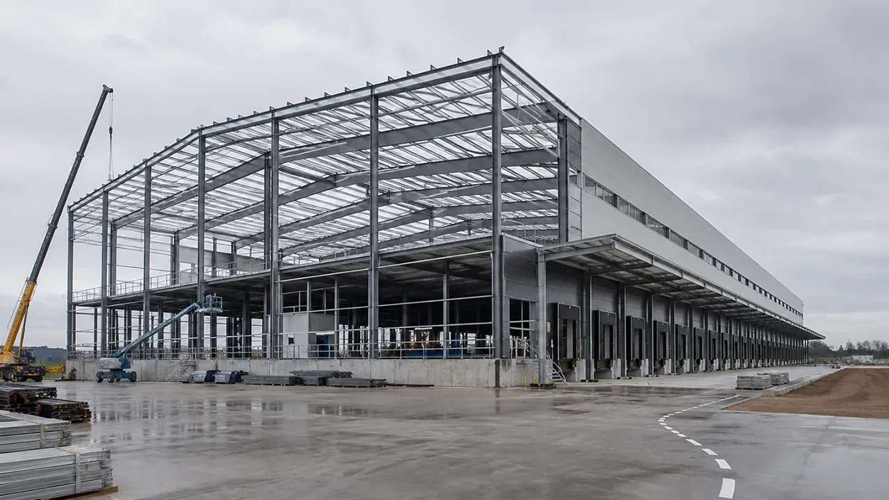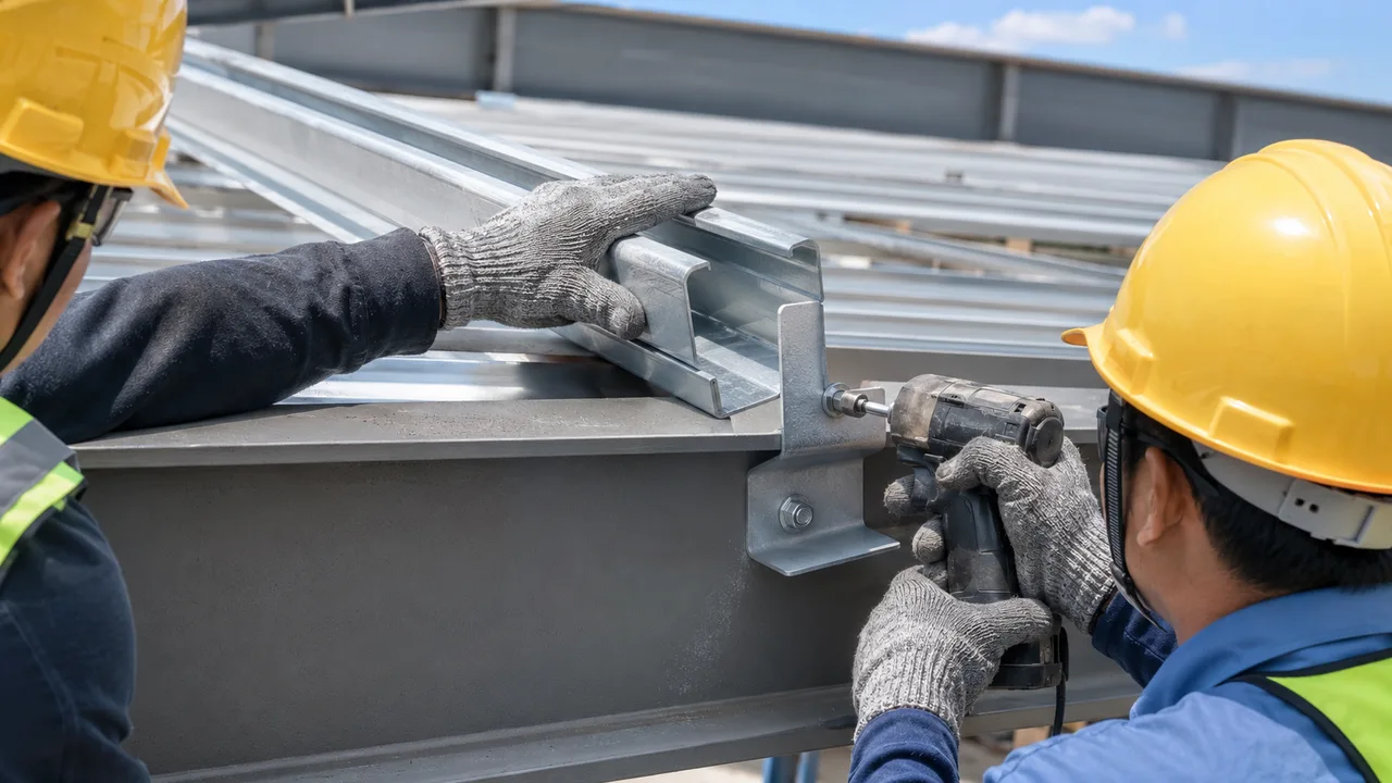
A roof purlin clip angle is a relatively small steel component, but its role in a roof framing system is important. It provides a practical connection between secondary roof members such as C or Z purlins and the primary supporting structure, including rafters, roof beams, and steel trusses. When the connection is properly detailed, fabricated, and installed, it helps maintain purlin alignment while transferring the required forces into the main structural frame.
Because clip angles are repeated across many roof bays, even a small detailing or fabrication error can become a widespread installation problem. Incorrect elevation, reversed orientation, mismatched bolt holes, or poor coordination with the supporting member can affect the roof plane, delay erection, and create unnecessary field modifications.
For that reason, clip angle design should be treated as part of the complete roof load path rather than as a minor accessory connection.
What Is a Roof Purlin Clip Angle?
A roof purlin clip angle is generally a short L-shaped steel angle used to connect a purlin to its supporting structural member. One leg of the angle is attached to the rafter, beam, or truss, while the other provides the connection to the purlin.
Depending on the structural and fabrication strategy, the clip may be:
- shop welded to the primary member and field bolted to the purlin,
- bolted on both sides where the supporting geometry allows it, or
- incorporated into a more specialized connection arrangement.
The exact detail depends on the purlin section, roof slope, connection forces, bolt arrangement, fabrication method, and erection sequence.
A clip angle should not automatically be treated as interchangeable with a cleat plate, seat angle, or general connection plate. These components may perform similar connection functions, but their geometry and structural behavior can differ.
Main Function of a Roof Purlin Clip Angle
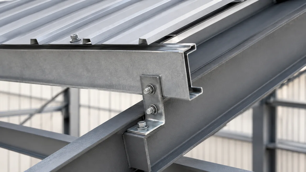
The primary purpose of the connection is to provide a secure interface between the secondary roof framing and the main steel structure.
Connecting Purlins to Primary Steel Members
Purlins transfer loads from the roofing system toward the main structural frame. The clip angle provides one of the common connection paths between the purlin and:
- portal frame rafters,
- roof beams,
- roof trusses,
- built-up steel members, and
- other engineered primary supports.
The connection should match the structural assumptions used in the roof design. The required capacity may vary from one part of the building to another.
Maintaining Purlin Position and Alignment
Clip angles also help establish the correct purlin spacing and elevation.
Consistent positioning matters because roof panels, insulation systems, bridging, bracing, gutters, skylights, and other roof components depend on an accurate secondary framing layout.
If several clips are welded at different elevations, the resulting purlins may not form a consistent roof plane. This can make roof panel installation more difficult and produce unwanted local distortion.
Transferring Connection Forces
The connection may need to transfer forces associated with:
- gravity loading,
- wind uplift,
- shear,
- purlin restraint, and
- other forces defined by the structural system.
Not every clip angle carries the same combination or magnitude of forces. Connection design should therefore be based on the actual structural requirements rather than a generic shop detail applied throughout the building without verification.
Where Is the Roof Purlin Clip Angle Installed?
Clip angles are normally located where each purlin meets a supporting primary member. Their exact orientation and elevation depend on the roof geometry and purlin arrangement.
Connection to Rafters
In portal frame buildings, clips are commonly attached along the roof rafter at the required purlin spacing.
The clip position must coordinate with:
- roof slope,
- purlin depth,
- rafter geometry,
- roof sheeting level, and
- bracing locations.
Repeated positioning accuracy is particularly important because an error at one support line can continue across multiple bays.
Connection to Roof Trusses
For truss-supported roofs, purlin connections should be coordinated with the top chord and the structural configuration of the truss.
Where practical, load introduction should correspond with intended structural connection locations rather than creating unnecessary local bending in truss components.
Purlin spacing should therefore be coordinated early with truss panel geometry, roof layout, and secondary framing requirements.
Ridge and Eave Conditions
Connections near the ridge or eaves may differ from typical intermediate roof locations.
Changes in roof slope, eave geometry, edge purlins, gutters, fascia framing, or other roof components may require modified clip orientation or a different connection arrangement.
Using one detail everywhere without considering these transitions can create clashes during fabrication or erection.
Roof Purlin Clip Angle Connection Details
The performance of a roof purlin clip angle depends on more than the angle itself. Angle thickness, bolt layout, welds, hole positioning, supporting member geometry, and installation access all influence the final connection.
Angle Size and Thickness
Angle dimensions should be suitable for the connection forces and the selected bolt or weld arrangement.
Relevant considerations include:
- purlin reaction,
- connection eccentricity,
- bolt diameter,
- edge distance,
- weld length,
- steel grade, and
- available connection space.
A standard angle size should not be selected solely because it is commonly available in the workshop. The detail must still satisfy the requirements of the specific connection.
Bolt Holes and Bolt Arrangement
Hole positioning has a direct effect on erection efficiency.
The detail must provide adequate spacing and edge distances while allowing bolts to be inserted, tightened, and inspected. Hole locations on the clip and purlin should also match accurately enough for practical field assembly.
Poor hole coordination can lead erection teams to force members into position or attempt unauthorized field modifications.
Welded Clip Angle Details
A common arrangement is to weld the clip angle to the primary steel member in the fabrication shop and bolt the purlin to the clip during erection.
Shop welding can provide better control over:
- clip position,
- weld preparation,
- weld quality,
- dimensional inspection, and
- surface preparation.
However, welding can also introduce local distortion if the sequence and heat input are poorly controlled.
The clip must remain at the correct orientation and elevation after welding.
Bolted Clip Angle Details
Bolted connections can support fast field assembly and may provide useful erection tolerance where properly designed.
The arrangement must still provide sufficient access for installation tools and bolt tightening. Nearby flanges, webs, bracing members, or other clips should not block the connection.
Connections to C and Z Purlins
C and Z purlins have different geometries, and their orientation can affect the connection detail.
Designers and fabricators should consider:
- web position,
- flange direction,
- lap arrangements,
- bolt-hole locations,
- purlin rotation, and
- installation access.
For lapped Z purlins, the connection area may become more congested because multiple purlin layers, bolts, and supporting components must fit within a relatively small region.
How Loads Pass Through the Clip Angle Connection
Understanding the load path helps explain why connection detailing matters.
Gravity Loads
Roof sheeting and other roof components transfer gravity loads to the purlins. The purlins then deliver their reactions through the connection into the supporting rafter, beam, or truss.
From there, forces continue through the primary framing toward columns and foundations.
A weakness or incorrect detail at the purlin connection can interrupt this intended load path.
Wind Uplift
Roof connections must not be considered only for downward gravity loading.
Wind can create uplift forces that act in the opposite direction. These forces may influence bolts, welds, local purlin behavior, and the connection between the clip and primary member.
Edge and corner roof areas can also experience different wind effects from internal roof zones, which is another reason connection requirements should not automatically be assumed identical throughout the building.
Lateral and Restraint Forces
Depending on the structural arrangement, purlins can contribute to roof stability, restraint, or diaphragm-related behavior.
The clip connection should be compatible with the assumptions used in the structural analysis. A connection intended only for a simple vertical reaction should not automatically be assumed to provide significant lateral restraint unless it is detailed for that purpose.
Placement Around Rafters, Trusses, and Local Reinforcement
The supporting primary member also needs to be considered when detailing a purlin connection.
Clip Placement on Supporting Members
Clip angles may connect near the flange or web region of a rafter, beam, or built-up member depending on the structural configuration.
The designer should consider whether the applied reaction introduces local effects into the supporting component and whether sufficient space exists for welding, bolting, coating, and inspection.
Connection eccentricity should also be minimized or explicitly considered in the design.
When Local Reinforcement May Be Required
Not every purlin connection requires additional reinforcement. However, concentrated forces, unusual connection geometry, heavy local reactions, or other structural conditions can create localized demand in the supporting steel member.
Where these effects become significant, the broader supporting member design may include reinforcement such as web stiffeners and flange stiffeners to control local behavior and maintain an effective force-transfer path.
The requirement should come from structural analysis rather than being added automatically to every purlin support.
Fabrication Details That Affect Installation
Many field problems originate in the fabrication stage rather than during erection.
Accurate Hole Positioning
Bolt holes should correspond with the approved shop drawings and purlin fabrication data.
CNC drilling or punching can help maintain repeatability, but production accuracy still depends on correct drawings, machine setup, member identification, and inspection.
Clip Angle Welding Position
When clips are shop welded, their:
- spacing,
- elevation,
- orientation, and
- projection
should be verified before the primary member leaves the fabrication facility.
A clip installed on the wrong side or at the wrong elevation can cause significant difficulties on site.
Marking and Identification
Clear member marks can help erection teams identify which purlins and supporting members belong to each roof grid or bay.
Where clips have different left-hand and right-hand orientations or special ridge and eave conditions, identification becomes especially valuable.
Surface Treatment
Painting or galvanizing requirements should be coordinated with welding and field assembly.
Damaged coating around welds, bolts, lifting points, or field modifications should be repaired according to the project coating requirements to maintain corrosion protection.
Roof Purlin Clip Angle Installation Process
A practical installation sequence can include:
- Verify primary frame alignment before installing secondary roof framing.
- Check clip locations against the erection drawings.
- Confirm the correct purlin mark and orientation.
- Position the purlin at the designed elevation.
- Align the purlin holes with the clip angle holes.
- Install the specified bolts without forcing misaligned members together.
- Check purlin spacing and roof slope.
- Tighten the connections according to the project requirements.
- Install bridging and bracing where required.
- Complete an alignment and connection inspection before roof sheeting begins.
Field teams should avoid correcting significant fabrication discrepancies by uncontrolled cutting, drilling, heating, or bending unless the modification has been reviewed and approved.
Installation Tolerances and Alignment
Accurate secondary framing helps create a consistent roof surface.
Purlin Spacing
Roof panel systems rely on predictable support spacing. Significant deviations can affect panel fastening locations, sidelaps, insulation, and roof accessories.
Elevation and Roof Plane
A single small elevation error may appear minor, but repeated differences across several support lines can create an uneven roof plane.
Clip elevations should therefore be checked as part of fabrication and erection quality control.
Hole Alignment
Misaligned holes should be investigated rather than automatically enlarged.
The cause may be an incorrectly fabricated clip, wrong purlin, reversed member, distorted primary frame, or accumulated dimensional tolerance.
Purlin Rotation
Cold-formed C and Z sections can be relatively slender and may rotate during handling or erection.
Correct clip orientation, bridging, restraint, and installation sequencing help maintain the required purlin position.
Common Roof Purlin Clip Angle Installation Problems
| Problem | Possible Cause | Potential Result |
|---|---|---|
| Bolt holes do not align | Fabrication tolerance, incorrect member, or frame misalignment | Difficult erection and field modification |
| Clip installed backward | Orientation or marking error | Purlin cannot be positioned correctly |
| Incorrect clip elevation | Fabrication or welding error | Uneven roof plane |
| Purlin forced into position | Alignment or dimensional problem | Local deformation or residual stress |
| Incomplete bolt installation | Erection oversight | Reduced connection performance |
| Damaged protective coating | Handling, welding, or field modification | Higher corrosion risk |
| Missing clip or fastener | Fabrication or erection error | Incomplete structural connection |
Common Design and Detailing Mistakes
Several recurring mistakes can reduce connection efficiency or create unnecessary work on site:
- assuming every purlin reaction is identical,
- using one clip detail throughout the roof without verification,
- ignoring wind uplift,
- providing inadequate bolt edge distance,
- blocking bolt access with adjacent members,
- creating interference with roof bracing,
- failing to coordinate purlin lap locations,
- placing connections away from the intended support point,
- ignoring erection tolerances, and
- allowing uncontrolled field modifications.
Good connection detailing should consider design, fabrication, transport, erection, and inspection together.
Roof Purlin Clip Angle vs Other Purlin Connection Methods
Clip angles are only one possible purlin connection method.
| Connection Type | Typical Advantage | Main Consideration |
|---|---|---|
| Clip angle | Simple and practical connection | Correct orientation and bolt layout |
| Cleat plate | Compact detailing | Plate thickness and connection arrangement |
| Direct bolted connection | Fewer separate components | Supporting geometry must permit direct fastening |
| Welded bracket | Controlled shop-fabricated support | Additional welding and fabrication |
| Seat-type connection | Provides direct bearing | Additional steel and detailing |
The preferred method should be selected according to structural requirements and the complete fabrication and erection strategy.
Inspection Checklist Before Roof Installation
Before roof sheeting is installed, the secondary framing should be checked for:
- correct clip locations,
- correct purlin orientation,
- required bolt quantity,
- proper bolt installation,
- acceptable weld condition,
- consistent purlin spacing,
- correct elevations,
- required bridging and bracing,
- coating damage requiring repair,
- unauthorized hole enlargement or field cutting, and
- visible local deformation.
Completing these checks before roofing installation makes connection problems easier to identify and correct.
Choosing the Right Roof Purlin Clip Angle Detail
The appropriate roof purlin clip angle detail depends on the complete structural arrangement rather than a single standard dimension.
Important factors include:
- purlin type and size,
- supporting member geometry,
- roof slope,
- purlin span,
- support reactions,
- wind uplift,
- bolt arrangement,
- weld requirements,
- fabrication method,
- erection sequence,
- corrosion protection, and
- applicable project design requirements.
Standardization can improve fabrication efficiency when several connections have genuinely similar requirements. However, standardization should follow engineering verification rather than replace it.
Roof Purlin Clip Angles in a Complete Steel Roof System
A clip angle may be small compared with a roof truss, rafter, or portal frame, but the quality of the connection directly affects secondary framing alignment and the transfer of roof forces.
Effective roof construction therefore depends on coordination between engineering, shop detailing, fabrication accuracy, member identification, erection planning, and field inspection.
For XTD Steel Structure projects, secondary framing connections are considered together with the primary structural system so that fabrication and site installation can follow coordinated project drawings.
A properly designed and installed roof purlin clip angle should provide the required connection capacity while remaining practical to manufacture, transport, assemble, inspect, and maintain as part of the complete steel roof system.
Common Roof Purlin Clip Angle Installation Problems
Even when the structural design is correct, installation problems can occur if fabrication tolerances, member identification, or erection procedures are not properly controlled.
| Problem | Possible Cause | Potential Result |
|---|---|---|
| Bolt holes do not align | Fabrication tolerance, incorrect member, or frame misalignment | Difficult erection and unnecessary field modification |
| Clip angle installed backward | Orientation or marking error | Purlin cannot be positioned correctly |
| Incorrect clip elevation | Fabrication or welding error | Uneven roof plane |
| Purlin forced into position | Alignment or dimensional problem | Local deformation or residual stress |
| Incomplete bolt installation | Erection oversight | Reduced connection performance |
| Damaged protective coating | Handling, welding, or field modification | Higher corrosion risk |
| Missing clip or fastener | Fabrication or erection error | Incomplete structural connection |
Bolt-hole misalignment is one of the most common practical problems. When holes do not match, the cause should be identified before any modification is made. The problem may come from an incorrectly fabricated clip, the wrong purlin being installed, an incorrectly oriented member, or accumulated frame tolerances.
Forcing the purlin into place can introduce deformation that was never considered in the structural design. Likewise, enlarging holes or cutting the connection without approval can reduce edge distance, alter bolt behavior, or damage protective coatings.
Common Design and Detailing Mistakes
Connection problems often begin during detailing rather than erection. Several recurring mistakes can reduce connection efficiency or create unnecessary work on site.
Using One Clip Detail Everywhere
It can be convenient to standardize a single clip angle throughout a roof. Standardization is useful when the structural requirements are genuinely similar, but roof reactions can vary according to location.
Edge zones, corner zones, ridge areas, eaves, large openings, equipment loads, and changes in purlin span can produce different connection demands.
Using the same connection everywhere without verification may therefore result in either inadequate capacity or unnecessary steel and fabrication.
Ignoring Wind Uplift
A purlin connection must not be designed only for downward gravity reactions.
Wind uplift can reverse the direction of force and change how bolts, welds, and cold-formed purlin material behave. The connection should be checked for the relevant load combinations and roof zones.
Insufficient Bolt Edge Distance
Trying to fit bolts into a small clip can result in inadequate edge distance or spacing.
The connection geometry must provide sufficient steel around each hole and enough room for proper bolt installation. Increasing bolt diameter without increasing the clip dimensions may not provide a valid solution.
Poor Access for Bolting
A connection can appear simple on a drawing but become difficult to assemble when nearby structural components block access.
Rafter flanges, stiffeners, bracing plates, roof bracing, adjacent purlins, and other connections should be considered when locating bolts.
Workers must have enough space to insert bolts, install washers and nuts, and use the required tightening tools.
Interference with Purlin Laps
Lapped Z purlins can create congested connection regions.
The detail should account for:
- both purlin thicknesses,
- lap bolts,
- clip bolts,
- supporting member geometry, and
- installation access.
Poorly coordinated lap details can make field assembly unnecessarily difficult.
Uncontrolled Field Modifications
Field modifications should not become the normal solution for fabrication errors.
Unapproved drilling, slotting, flame cutting, welding, bending, or removal of connection material can alter structural performance and corrosion protection.
Any significant discrepancy should be reviewed before modification.
Roof Purlin Clip Angle vs Other Purlin Connection Methods
A clip angle is one practical option for connecting purlins to the primary steel frame, but it is not the only solution.
Different projects may use cleat plates, direct bolted connections, welded brackets, or seat-type details depending on the supporting geometry and structural requirements.
| Connection Type | Typical Advantage | Main Consideration |
|---|---|---|
| Clip angle | Simple and practical connection | Correct orientation and bolt layout |
| Cleat plate | Compact connection arrangement | Plate thickness and connection detailing |
| Direct bolted connection | Fewer separate components | Supporting geometry must allow direct fastening |
| Welded bracket | Controlled shop-fabricated support | Additional welding and fabrication |
| Seat-type connection | Can provide direct bearing support | Additional steel and detailing |
The best solution is not necessarily the connection with the fewest components. The selected detail should provide adequate structural performance while remaining practical to fabricate, coat, transport, install, and inspect.
Inspection Checklist Before Roof Installation
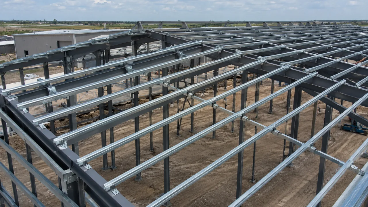
Secondary roof framing should be inspected before roof panels conceal the connections.
Important checks include:
- correct clip angle locations,
- correct purlin orientation,
- required bolt quantity,
- proper bolt installation and tightening,
- acceptable weld condition,
- consistent purlin spacing,
- correct purlin elevation,
- required bridging and bracing,
- repair of damaged protective coatings,
- absence of unauthorized hole enlargement or field cutting, and
- absence of visible local deformation.
Inspection before roof sheeting is especially useful because both sides of the connection remain accessible.
Once roofing, insulation, ceilings, or services are installed, identifying and correcting connection problems can become more difficult and expensive.
Choosing the Right Roof Purlin Clip Angle Detail
The correct roof purlin clip angle cannot be selected only by choosing a commonly available steel angle.
The connection must reflect the complete structural arrangement.
Important design and detailing factors include:
- purlin type,
- purlin depth and thickness,
- supporting member geometry,
- roof slope,
- purlin span,
- support reaction,
- wind uplift,
- bolt diameter and arrangement,
- weld requirements,
- connection eccentricity,
- fabrication method,
- erection sequence,
- corrosion protection, and
- applicable structural design requirements.
A connection suitable for a light roof purlin may not be appropriate for a larger section carrying greater reactions. Likewise, a clip that works well at an intermediate rafter may require modification near an eave, ridge, purlin lap, or special roof opening.
Consider the Purlin Type
C and Z sections behave differently during erection and may require different clip orientation or bolt positioning.
Z purlins are frequently used in continuous or lapped arrangements, while C purlins may be used where a non-lapped or different secondary framing configuration is preferred.
Connection detailing should correspond with the actual purlin arrangement rather than using a generic representation.
Consider the Supporting Structure
The supporting member may be:
- a hot-rolled rafter,
- a welded built-up rafter,
- a roof truss chord,
- a structural beam, or
- another engineered steel component.
Each support type provides different space, stiffness, thickness, and connection possibilities.
The designer must consider both the clip angle itself and the local behavior of the supporting member.
Consider Fabrication Efficiency
Where many identical connections are structurally appropriate, standardization can reduce:
- shop detailing time,
- fabrication setup,
- marking complexity,
- inspection effort, and
- erection confusion.
However, standardization should follow engineering verification rather than replace it.
A practical approach may involve several standardized clip families for different roof zones instead of forcing one connection detail to serve every condition.
Consider Installation Before Finalizing the Detail
Connection design should also answer practical erection questions:
- Can workers access the bolts?
- Can the purlin be lowered into position without interference?
- Is there enough tolerance for normal fabrication and frame erection variation?
- Can the connection be inspected after assembly?
- Does the detail conflict with roof bracing or another member?
- Can damaged coating be repaired?
A structurally adequate detail that cannot be assembled efficiently on site is not an optimized connection.
Why Connection Coordination Matters for the Entire Roof
Purlin connections interact with more roof components than may initially be obvious.
Secondary framing must coordinate with:
- roof sheeting,
- insulation,
- bridging and sag rods,
- roof bracing,
- gutters,
- ridge details,
- skylights,
- roof openings,
- smoke vents,
- solar mounting systems,
- HVAC equipment, and
- maintenance access systems.
A small change to purlin elevation or position can affect several of these components.
This is why structural drawings, fabrication drawings, secondary framing layouts, and architectural roof details should be coordinated before production begins.
Installation Quality and Long-Term Performance
A properly installed connection should continue to perform throughout the service life of the building.
Long-term performance depends on more than initial connection capacity.
Corrosion Protection
Roof framing may be exposed to condensation, moisture, industrial environments, or aggressive atmospheric conditions.
Painted or galvanized connection components should receive the specified protection, and damaged areas should be repaired after fabrication and erection.
Particular attention may be required around:
- field welds,
- abrasion from handling,
- bolt installation areas,
- site modifications, and
- locations where water can collect.
Future Roof Modifications
Roof systems often change during the life of a building.
Owners may later install:
- solar panels,
- new HVAC equipment,
- ductwork,
- ceilings,
- pipes,
- cable trays,
- lighting, or
- maintenance platforms.
These additions should not automatically be attached to purlins or clip angles without checking the existing structural capacity.
A connection designed for the original roof loads may not have reserve capacity for significant new suspended equipment.
Periodic Inspection
Where roof framing remains accessible, periodic inspections can identify:
- corrosion,
- loose or missing fasteners,
- local deformation,
- damaged coating,
- unapproved modifications, and
- changes caused by newly installed equipment.
Early identification can prevent minor connection issues from developing into more significant maintenance problems.
Roof Purlin Clip Angle in a Complete Steel Roof System
A clip angle is small compared with a roof truss, rafter, or portal frame, but its function is directly connected to the performance of the secondary roof framing.
The connection helps establish purlin position, provides a path for structural forces, and supports efficient assembly of the roof system. When the same connection is repeated across dozens or hundreds of locations, accuracy becomes especially important.
Good performance depends on coordination between:
- structural engineering,
- connection detailing,
- shop fabrication,
- quality control,
- member identification,
- transport planning,
- site erection, and
- final inspection.
For XTD Steel Structure projects, secondary framing connections can be coordinated with the primary framing, fabrication drawings, and erection requirements so the roof system can be produced and assembled as an integrated structure.
A properly engineered roof purlin clip angle should provide the required connection capacity without creating unnecessary fabrication or installation complexity. When placement, bolt arrangement, welds, tolerances, supporting member behavior, and erection access are considered together, this small connection component can contribute to a more accurate, efficient, and reliable steel roof system.