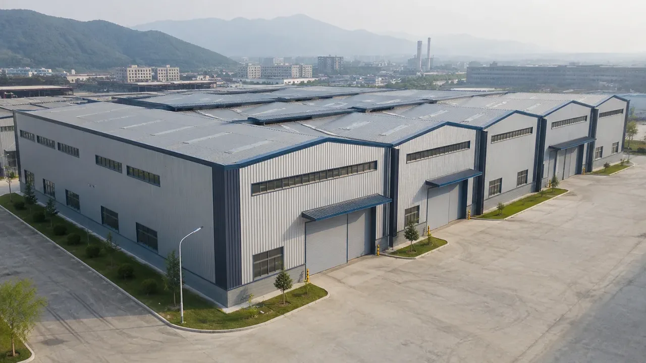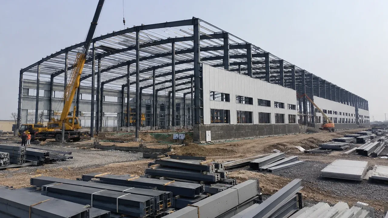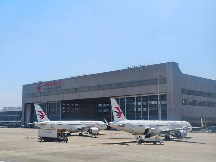
In a steel building, the strength of the structure does not come only from the main steel members. It also depends on how those members are connected. For roof trusses, beams, columns, bracing, and support frames, connection design affects load transfer, installation accuracy, long-term stability, and overall project efficiency. That is why steel structure connection details for trusses must be reviewed carefully before fabrication and site erection begin.
A truss may look simple from a distance, but every node, plate, bolt, weld, and support point has a specific function. If one connection is unclear or poorly coordinated, the result can be difficult site assembly, extra rework, structural stress concentration, or delays during installation. For industrial buildings, warehouses, factories, halls, stations, and long-span roof systems, proper detailing is one of the most important parts of successful steel construction.
This article explains the key connection details used in trusses, beams, and columns, including bolted joints, welded joints, gusset plates, splice connections, support details, and steel structure connection details used in more complex roof systems such as a space truss.
Why Connection Details Matter in Steel Truss Structures
A steel truss works by transferring forces through a network of chords, diagonals, vertical members, and support points. The top chord, bottom chord, and web members all carry different types of force depending on the span, roof load, wind condition, and building design. However, these forces can only move safely through the structure when the connection details are properly designed.
In a typical roof truss system, loads are transferred from roof panels and purlins into the truss, then from the truss into beams, columns, and finally into the foundation. If the connection between these elements is weak, misaligned, or difficult to install, the whole load path can be affected.
Good steel structure connection details for trusses help achieve several important goals:
- Transfer loads clearly between truss members, beams, columns, and supports.
- Reduce site assembly problems caused by misaligned bolt holes or unclear plate positions.
- Improve fabrication accuracy through detailed cutting, drilling, and welding drawings.
- Support faster erection by making each joint easier to identify and install.
- Improve long-term structural performance by reducing stress concentration at critical nodes.
Main Types of Steel Structure Connection Details for Trusses
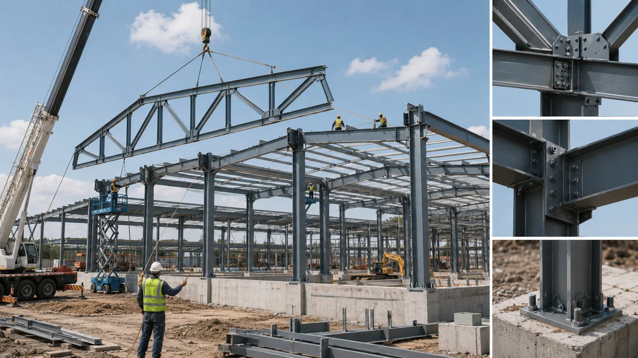
Different projects use different connection methods depending on the building type, member size, span, load requirements, fabrication method, transportation limit, and installation sequence. The most common connection details for steel trusses include bolted connections, welded connections, gusset plates, end plates, and splice plates.
Bolted Truss Connections
Bolted connections are widely used in steel truss construction because they are practical for site assembly. Large trusses are often fabricated in smaller sections, transported to the project site, and then connected using bolts. This method helps reduce transportation difficulty and makes the installation process more manageable.
For bolted truss connections, several details must be coordinated carefully. Bolt grade, bolt diameter, hole size, edge distance, plate thickness, and installation clearance all need to match the structural drawing. If bolt holes are not aligned correctly, workers may need to enlarge holes or modify plates on site, which can reduce accuracy and delay the project.
Bolted connections are commonly used for truss splices, beam-to-column joints, bracing connections, purlin seats, and support connections. They are also useful when future maintenance or disassembly may be required.
Welded Truss Connections
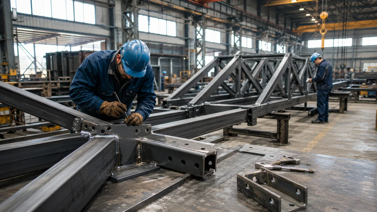
Welded connections are often completed in the factory before the steel components are shipped to site. Factory welding allows better control over weld quality, welding sequence, member alignment, and inspection. For many truss systems, welded joints are used to connect web members to chords or to form larger prefabricated truss sections.
Important welded connection details include weld size, weld length, weld position, welding access, groove preparation, and distortion control. The designer and fabricator must also consider whether the joint can be inspected properly after welding. A weld may look simple on the drawing, but if the joint is too crowded or difficult to reach, fabrication quality can become harder to control.
In many projects, welded and bolted details are combined. For example, a truss section may be welded in the factory and then bolted to another section or to the supporting column on site.
Gusset Plate Connections
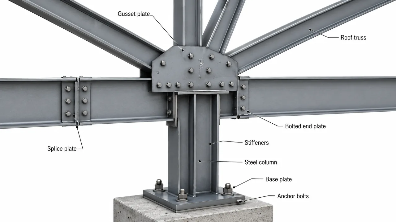
Gusset plates are among the most common connection details in truss construction. A gusset plate is used to connect multiple members at one node, such as the top chord, bottom chord, diagonal web member, and vertical member. Depending on the design, members may be bolted or welded to the plate.
The size and shape of a gusset plate should match the force direction and member arrangement. Plate thickness, bolt spacing, weld layout, edge distance, and clearance must be detailed clearly. If a gusset plate is too small, too thin, or too crowded, it can create fabrication and installation problems.
Gusset plates are especially important in long-span trusses because the force at each node can be significant. For this reason, they should not be treated as simple accessories. They are structural components that directly affect the performance of the truss.
End Plate and Splice Connections
End plates and splice plates are used when steel members or truss segments need to be joined together. Because large trusses are often too long to transport as a single piece, they are divided into sections. These sections are then reconnected on site using bolted splice details.
A good splice connection should provide accurate alignment, sufficient strength, and easy installation access. The splice plate should be positioned so workers can tighten bolts properly. The drawing should also show whether the splice is located in a high-force zone or a lower-force zone, because this affects the required plate and bolt design.
Steel Truss Connection Details by Member Position
Connection requirements vary depending on where the member is located in the truss. A top chord connection does not work the same way as a bottom chord connection. A web member node has different requirements from a truss support joint. Understanding these differences helps improve design coordination and fabrication quality.
Top Chord Connection Details
The top chord of a truss usually supports roof purlins, roof panels, insulation layers, and sometimes service loads. It may also be affected by wind uplift and compression forces. Connection details at the top chord should consider purlin seats, roof bracing, plate clearance, and load transfer from the roof system into the truss.
In industrial roof structures, the top chord connection must also coordinate with the roof slope and drainage direction. If purlin holes, clips, or support plates are not positioned correctly, roof installation can become difficult.
Bottom Chord Connection Details
The bottom chord is often affected by tension forces. In some buildings, it may also support ceiling systems, lighting, ducts, conveyors, or maintenance walkways. The connection details should therefore consider both structural forces and practical service loads.
Bottom chord splices should be detailed carefully because they help maintain the continuity of the truss. If the splice is poorly placed or under-designed, it can affect the overall behavior of the roof system.
Web Member Connection Details
Web members include diagonals and verticals. These members transfer forces between the top and bottom chords. At each node, web members usually connect through gusset plates, welded joints, or bolted plates.
The main challenge in web member detailing is node coordination. Several members may meet in a small area, so the plate layout must avoid overcrowding. The detail should provide enough space for bolts, welds, tools, coating, and inspection.
Truss Support Connection Details
The truss support connection transfers the roof load into the column, beam, bracket, or concrete support. This connection may include bearing plates, anchor bolts, seat plates, stiffeners, or support brackets. It must be strong enough to resist vertical loads, horizontal forces, and possible uplift depending on the building design.
For large-span steel buildings, the truss support detail is one of the most important points in the whole structure. Even if the truss itself is well designed, a weak or unclear support connection can create serious installation and performance issues.
Beam and Column Connection Details in Steel Structures
Trusses do not work alone. They are usually connected to beams, columns, portal frames, or other support systems. Because of this, beam and column connection details must be coordinated with the truss design from the beginning.
Beam-to-Column Connections
Beam-to-column connections are used to transfer forces between horizontal and vertical members. Depending on the structural system, the connection may be designed mainly for shear, moment resistance, or both. Common details include end plates, fin plates, angle cleats, bolted flange plates, welded plates, and stiffened joints.
In a simple support condition, the beam-to-column connection may mainly transfer vertical shear. In a rigid frame or moment-resisting system, the connection must also transfer bending forces. This difference must be reflected clearly in the drawing.
Column Base Connection Details
The column base connection links the steel structure to the foundation. It usually includes a base plate, anchor bolts, grout layer, leveling nuts, and sometimes stiffeners. The base plate must be sized to transfer column loads into the concrete foundation safely.
Anchor bolt layout is especially important. If anchor bolts are placed incorrectly, the steel column may not fit during installation. For this reason, anchor bolt templates and foundation coordination are often reviewed before steel erection begins.
Beam Splice and Column Splice Details
Long beams and columns may need splice connections because of transportation, fabrication, or installation limits. A splice detail should show plate size, bolt arrangement, weld requirements, member alignment, and installation position.
Column splices are often located at practical erection heights, while beam splices may be located where internal forces are suitable. These decisions should be coordinated between structural design, fabrication, transportation, and site installation teams.
Space Truss Connection Details
A space truss is different from a normal planar truss because it transfers loads in three dimensions. Instead of working mainly in one vertical plane, a space truss uses a network of members arranged in multiple directions. This makes the connection details more complex and more important.
Space truss systems may use spherical nodes, bolted ball nodes, welded node plates, or customized steel connectors depending on the project design. Each node may connect several members from different angles, so geometric accuracy is critical. Small errors in node position can affect the alignment of multiple members.
For long-span roofs, stadiums, exhibition halls, transport terminals, and public buildings, a space truss can provide strong and efficient roof support. However, it requires accurate fabrication, clear node numbering, careful pre-assembly planning, and detailed installation sequencing.
Design Factors That Affect Steel Structure Connection Details for Trusses
Proper steel structure connection details for trusses are not created randomly. They are based on engineering requirements, project conditions, fabrication methods, and site constraints. Several factors should be considered before the final connection design is approved.
Load Direction and Load Path
Every connection must be designed according to the direction and type of force it carries. Roof dead load, live load, wind load, seismic force, equipment load, and maintenance load may all affect connection design. A connection that works well for vertical load may not be suitable for uplift or lateral force.
Member Shape and Section Type
Steel trusses may use H-beams, box sections, round tubes, square tubes, angle steel, or channel steel. Each member type requires a different connection approach. Tube trusses, for example, often require careful cutting angles and welded node preparation, while H-beam trusses may use plates and bolts more easily.
Fabrication Method
Modern steel fabrication may include CNC cutting, drilling, welding, straightening, trial assembly, surface treatment, and component marking. Connection drawings should match the actual fabrication process. If the detail is difficult to cut, drill, weld, or inspect, it may need to be adjusted before production.
Installation Sequence
Connection details should also support the erection sequence. Large trusses may require temporary supports, lifting points, crane access, temporary bracing, and staged bolting. If the connection is strong but difficult to install, it can still create delays on site.
Corrosion Protection
Connection areas must be protected from corrosion. Paint, galvanizing, coating thickness, drainage, and water traps should be considered. In outdoor or humid environments, poor connection detailing can allow water to collect around plates, bolts, or welds, increasing the risk of corrosion over time.
Common Problems in Poor Truss Connection Detailing
Many steel structure problems do not come from the main member design. They come from unclear or incomplete connection details. Some common issues include:
- Bolt holes do not align during site installation.
- Gusset plates are too small or too crowded.
- Welds are difficult to access or inspect.
- Bracing connection points are missing from the drawing.
- Truss support plates do not match column positions.
- Anchor bolt layout does not match the column base plate.
- Splice plates are hard to install because of limited tool clearance.
- Paint or galvanizing thickness affects bolt fit-up.
- Installation tolerance is not considered during design.
These issues can lead to site modification, delayed erection, additional labor cost, and reduced construction quality. Reviewing connection details before fabrication is therefore much more efficient than correcting problems after the steel components arrive on site.
How XTD Steel Structure Handles Truss Connection Details
XTD Steel Structure provides integrated steel structure services covering design coordination, processing, fabrication, installation support, and project management. For truss systems, beams, columns, and space truss projects, connection details are reviewed according to the project span, load requirements, member type, fabrication process, and site erection plan.
During production, details such as cutting length, drilling position, bolt layout, weld size, plate thickness, component marking, and pre-assembly requirements must be controlled carefully. This helps reduce installation mismatch and supports smoother site progress.
For warehouses, factories, industrial buildings, long-span roofs, and public steel structures, XTD Steel Structure focuses on practical detailing that connects engineering design with real fabrication and installation conditions.
Checklist Before Approving Steel Truss Connection Drawings
Before fabrication begins, project owners, contractors, and engineers should review the connection drawings carefully. The following checklist can help identify key points:
- Are all truss nodes clearly shown?
- Are bolt grades, bolt diameters, and hole sizes specified?
- Are weld sizes, weld lengths, and weld positions marked?
- Are gusset plates sized properly for each node?
- Are beam-to-column connection details clear?
- Are column base plates and anchor bolts coordinated with the foundation?
- Are bracing connection points included?
- Are transport and site assembly joints clearly identified?
- Are coating, painting, or galvanizing requirements considered?
- Are installation tolerances and erection sequence considered?
This review process helps ensure that steel structure connection details for trusses are not only structurally suitable but also practical for fabrication, transport, and installation.
FAQ About Steel Structure Connection Details for Trusses
What Are the Most Common Steel Truss Connection Details?
The most common steel truss connection details include bolted connections, welded connections, gusset plates, splice plates, end plates, support bearing plates, and bracing connection plates. The right detail depends on the truss type, load condition, member section, and installation method.
Why Are Gusset Plates Used in Truss Connections?
Gusset plates are used to connect multiple truss members at one node. They help transfer forces between chords, diagonal members, vertical members, beams, or columns. A proper gusset plate detail improves load transfer and installation accuracy.
Are Bolted or Welded Truss Connections Better?
Both methods can be suitable. Bolted connections are easier for site assembly and future adjustment, while welded connections are often used in factory fabrication for accuracy and continuity. Many steel truss projects use a combination of both methods.
What Is Different About Space Truss Connection Details?
A space truss transfers loads in three dimensions, so its nodes must connect several members from different directions. This requires higher geometric accuracy, clearer node numbering, and more careful fabrication control than a simple planar truss.
Why Should Connection Details Be Reviewed Before Fabrication?
Connection details should be reviewed before fabrication because errors in plates, holes, welds, bolts, or support positions can cause site installation problems. Early review helps reduce rework, improve quality, and keep the steel structure project on schedule.