Every steel building frame depends on a clear load path. Some forces move downward through beams and columns, while other forces travel directly along the length of structural members. These direct forces are known as axial loads. In practical steel design, understanding compression and tension axial loads is essential because columns, bracing members, truss chords, and web members do not all behave the same way under force.
A compression force pushes a member together, while a tension force pulls a member apart. Both force types may appear in the same building frame, sometimes even in the same truss or bracing system under different load cases. If the designer treats compression and tension as identical, the structure may face buckling, connection failure, eccentric loading, or unstable force transfer.
What Are Compression and Tension Axial Loads?
An axial load acts along the centerline of a structural member. When the load direction is aligned with the member length, the force mainly produces either compression or tension instead of bending. This is why axial members can be very efficient in steel buildings. They transfer force directly from one point to another with relatively economical steel usage, provided that the member and its connections are designed correctly.
Compression Axial Loads
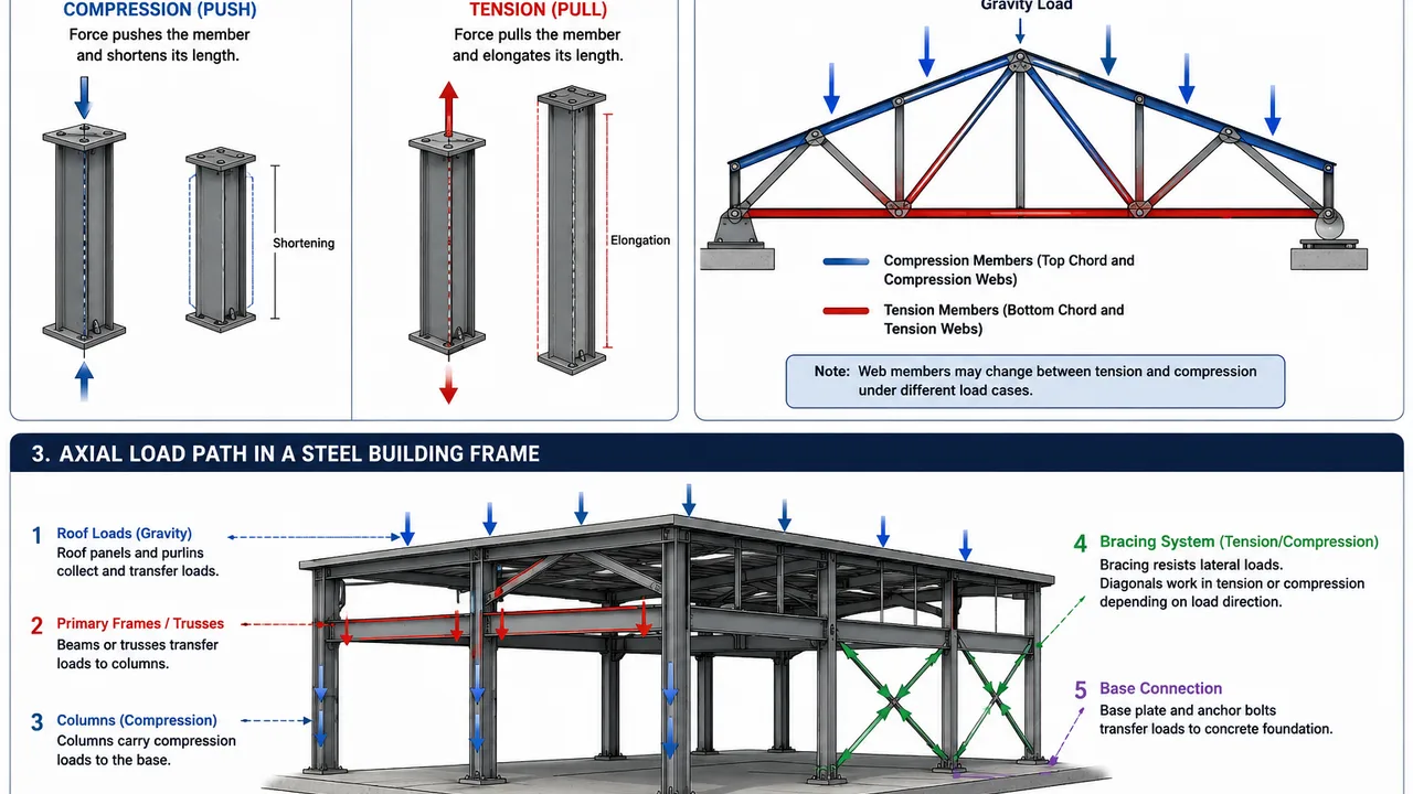
Compression axial loads push a member inward along its length. In steel building frames, this condition is common in columns, top chords of roof trusses, compression braces, and some truss web members. The main design concern is stability. A steel member may have enough material strength, but if it is long, slender, or poorly restrained, it can buckle before the steel reaches its full yield capacity.
This makes compression design more than a simple strength check. Engineers must evaluate unsupported length, slenderness ratio, weak-axis behavior, end restraint, bracing position, and connection alignment. A large steel section is not automatically safe if the member is not properly restrained against buckling.
Tension Axial Loads
Tension axial loads pull a member outward along its length. This condition is common in tie rods, bottom chords of roof trusses, cross bracing members, and some diagonal truss members. Unlike compression members, tension members are not normally controlled by buckling. Instead, they are often controlled by net section capacity and connection strength.
Bolt holes reduce the net area of a tension member. Welds, gusset plates, splice plates, and edge distances must also be designed to transfer the full axial force. A tension member may look simple, but the connection detail often determines whether the force can be transferred safely.
How Axial Loads Move Through Steel Building Frames
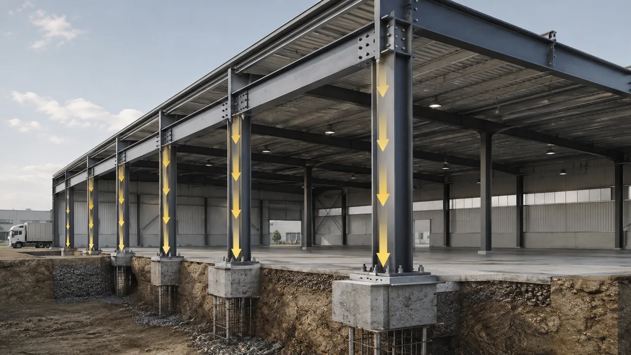
Steel building frames work as connected systems, not isolated members. Roof panels transfer load to purlins. Purlins transfer load to rafters, trusses, or primary frames. These members then transfer forces to columns, bracing systems, base plates, anchor bolts, and foundations. At each step, the load path must remain continuous.
In a typical industrial steel building, gravity loads create compression in columns and selected truss members. Wind loads may create tension in bracing members, uplift in anchor bolts, and force reversal in roof trusses. Crane loads, equipment vibration, mezzanine loads, and service platforms can add further complexity. This is why compression and tension axial loads must be reviewed under multiple load combinations instead of only one standard gravity condition.
Compression Axial Loads in Steel Columns
Columns are the most recognizable compression members in steel building frames. They transfer roof loads, floor loads, wall loads, crane reactions, and equipment loads to the foundation. Because columns often carry large axial force, their design must consider both material capacity and stability.
The effective length of a column strongly influences its compression capacity. A short, well-braced column can usually resist higher compression than a long, unbraced column with the same steel section. The support condition also matters. A column with a rigid frame connection may behave differently from a column in a braced frame. A fixed base, pinned base, or semi-rigid connection can change the buckling length and internal force distribution.
Compression is also affected by secondary forces. A column may carry axial compression while also resisting bending from wind, crane movement, eccentric loading, or frame sway. If the column is part of a portal frame, axial force and bending moment may act together. For this reason, column design in steel buildings should not rely only on direct axial compression checks.
Tension Axial Loads in Bracing Systems
Bracing systems help steel buildings resist lateral movement. They transfer wind, seismic force, and frame sway into the foundation. In many steel buildings, cross bracing is designed so that one diagonal works in tension while the opposite diagonal becomes less active under the same load direction. When the load direction reverses, the force pattern can reverse as well.
Tension bracing may use rods, angles, flat bars, channels, or other steel sections. The member itself must have enough tensile capacity, but the connection is equally important. Bolt holes reduce the net section. Gusset plates must have enough thickness and edge distance. Welds must be sized to transfer the axial force without local failure.
Good bracing design also requires alignment. If the bracing member does not align with the intended force path, the connection may create eccentric loading. This can introduce bending into a member that was intended to carry direct tension only. For industrial steel buildings, this type of detailing error can reduce the effectiveness of the entire lateral stability system.
Compression and Tension in Truss Members
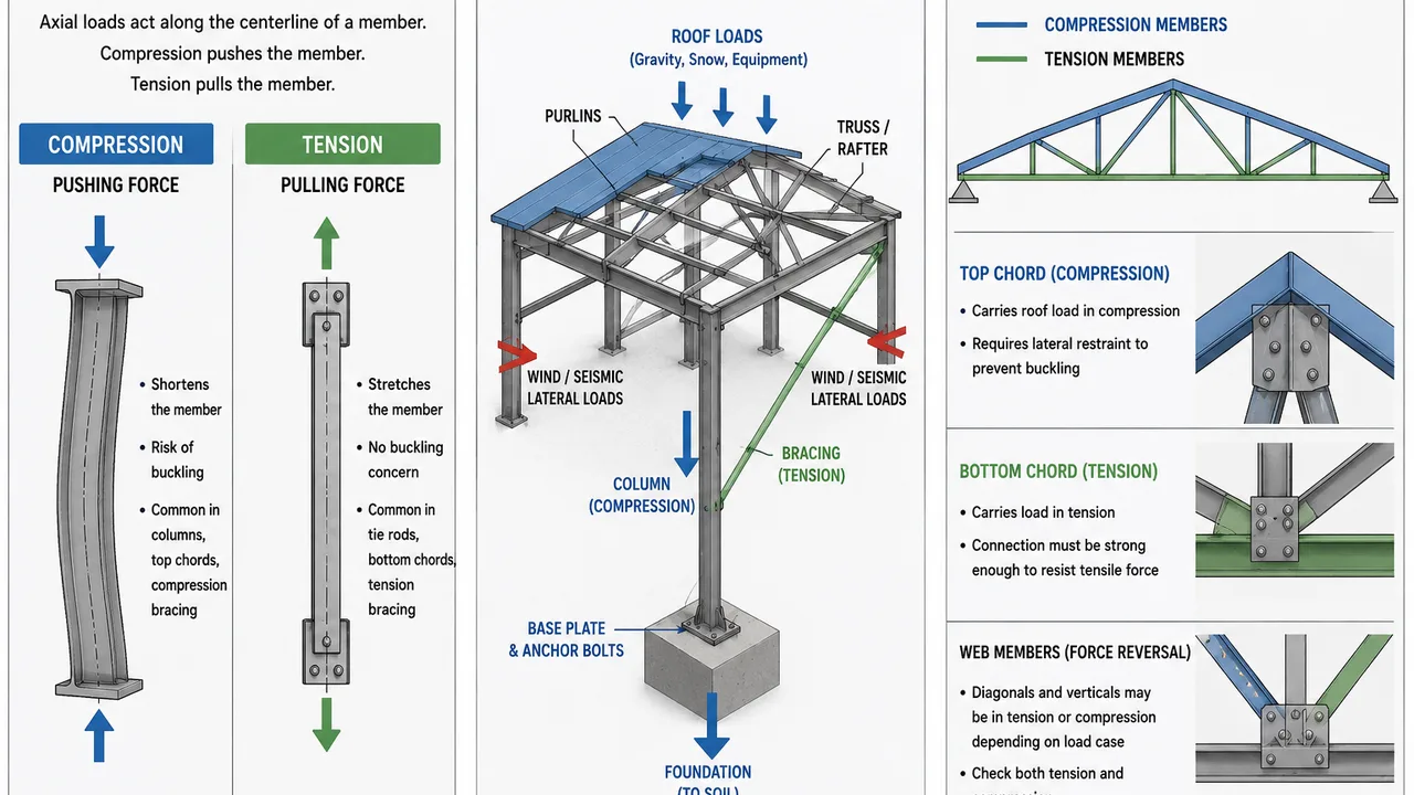
Truss systems are one of the clearest examples of how axial forces work in steel structures. A truss divides load into multiple members, with some working in compression and others working in tension. This allows long spans with efficient steel usage, especially in warehouses, factories, hangars, and large roof structures.
Top Chord Compression
The top chord of a roof truss often carries compression under gravity loads. Because it is a compression member, it needs proper lateral restraint. Purlins, roof bracing, and secondary framing can help prevent the top chord from buckling sideways. If these restraints are too far apart or too flexible, the chord may lose stability even when the steel section appears strong enough.
Bottom Chord Tension
The bottom chord of a typical roof truss often works in tension. It helps tie the truss system together and transfers force across the span. Because the bottom chord is usually connected at multiple panel points, its connection details must be designed to avoid tearing, bolt group failure, or excessive deformation.
Web Member Force Reversal
Diagonal and vertical web members may work in either compression or tension depending on the truss geometry and load condition. Wind uplift, partial loading, maintenance loads, or asymmetrical roof loads can cause force reversal. A member that is normally in tension under gravity load may need compression capacity under another load case.
Why Panel Point Alignment Matters
Because truss members transfer axial force through panel points, accurate steel truss connection details help reduce eccentricity and secondary bending. Ideally, the centerlines of connected members should meet at the node. If the joint geometry is offset, the truss may experience unintended bending that reduces the efficiency of the axial load path.
Compression and Tension in a Space Truss System
A space truss transfers axial forces in three dimensions. Unlike a flat truss that distributes force mainly in one plane, a space truss uses interconnected members and nodes to distribute load across a wider structural network. This makes it suitable for stadium roofs, exhibition halls, airport terminals, long-span industrial buildings, and large public structures.
In this type of system, many short members carry either tension or compression depending on their position and load case. Node accuracy is critical because each node may receive forces from several directions at the same time. Fabrication precision, assembly tolerance, and connection quality are therefore essential for maintaining a reliable force path in the entire space truss system.
Key Differences Between Compression and Tension Members
| Design Item | Compression Members | Tension Members |
|---|---|---|
| Main force behavior | Pushed together along the member length | Pulled apart along the member length |
| Main failure risk | Buckling or instability | Net section rupture or connection failure |
| Common examples | Columns, top chords, compression braces | Bottom chords, tie rods, tension braces |
| Key design factor | Slenderness, restraint, and effective length | Net area, bolt holes, and connection capacity |
| Connection concern | Eccentric compression and plate stability | Bolt group strength, welds, tearing, and elongation |
Why Buckling Controls Compression Design
Buckling is one of the biggest differences between compression and tension behavior. A compression member can fail by instability before the steel reaches its full material strength. The risk increases when the member is long, slender, weakly restrained, or loaded with eccentric force.
Weak-axis buckling is often more critical than strong-axis buckling. A member may appear strong in one direction but vulnerable in another. This is why purlin restraint, lateral bracing, member orientation, and connection stiffness must be considered during design. For truss top chords and compression web members, restraint spacing can directly affect axial capacity.
Why Connections Control Tension Design
Tension members are usually efficient because they are not controlled by buckling. However, they may fail at the connection if the detail is not properly designed. Bolt holes reduce the effective net section of the member. Welds must transfer the full axial force. Gusset plates must resist tearing, block shear, bearing, and local deformation.
In bracing and truss systems, the tension member is only as reliable as its connection. If the member is strong but the plate is thin, the bolt spacing is poor, or the weld is undersized, the axial load path becomes unsafe. This is why connection design should be reviewed together with member design, not as a separate afterthought.
Common Design Mistakes in Axial Load Transfer
One common mistake is treating compression and tension members as if they require the same design checks. Compression members need stability review, while tension members need careful net section and connection review. Using the same approach for both can lead to unsafe assumptions.
Another mistake is ignoring force reversal. In trusses and bracing systems, a member may change from tension to compression under wind uplift or reverse lateral loading. If the design only checks the most obvious load case, the member may not perform safely under real building conditions.
Misalignment is also a frequent issue. When member centerlines do not meet correctly at a joint, axial force may create eccentricity and secondary bending. This problem is especially important in truss nodes, bracing gussets, and frame connections where high axial forces must pass through compact connection areas.
How XTD Steel Structure Supports Axial Load Design
For steel warehouses, factories, long-span roof systems, and industrial buildings, understanding compression and tension axial loads is important from early design through fabrication and installation. XTD Steel Structure supports this process through structural coordination, member fabrication, connection detailing, quality inspection, and project installation support.
This integrated approach helps columns, bracing members, truss components, and connection plates work together as a complete steel frame system. Instead of treating each member as an isolated part, the design and fabrication process considers how force moves through the entire building frame.
Practical Takeaway for Steel Building Frames
Compression and tension axial loads must be understood together in steel building frame design. Compression members require stability checks, restraint planning, and buckling control. Tension members require net section checks, bolt and weld review, and reliable connection detailing. Truss and bracing systems require accurate alignment so axial force can move cleanly through the structure.
For project owners, contractors, and engineers, a safe steel frame depends on more than selecting large steel sections. It depends on a continuous load path from roof to foundation, properly designed members, accurate fabrication, and connection details that match the real direction of force.
FAQ About Compression and Tension Axial Loads
What Are Compression and Tension Axial Loads?
Compression axial loads push a member together along its length, while tension axial loads pull a member apart along its length. Both force types are common in steel building frames.
Which Steel Members Carry Compression Axial Loads?
Steel columns, top chords of roof trusses, compression braces, and some truss web members commonly carry compression axial loads.
Which Steel Members Carry Tension Axial Loads?
Bottom chords, tie rods, cross bracing members, and some diagonal truss members commonly carry tension axial loads.
Why Is Buckling Important in Compression Members?
Buckling is important because a compression member can lose stability before the steel reaches its full material strength, especially when the member is long, slender, or poorly restrained.
Why Are Connections Important for Tension Members?
Connections are important because tension force must pass through bolts, welds, gusset plates, and other connection components. A weak connection can fail even when the steel member itself has enough tensile capacity.