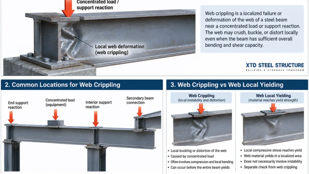
A steel beam can have adequate bending and shear capacity yet still develop a serious local problem where a heavy load or support reaction enters the section. When a concentrated force is introduced over a relatively short bearing length, the beam web may distort, buckle, or crush locally before the entire member reaches its overall capacity. This local behavior is known as web crippling.
The risk is especially important around beam supports, equipment reactions, transfer points, and other locations where large forces are delivered through a small area. Because the damage is highly localized, it can be overlooked if the design process focuses only on global bending, shear, and deflection.
Understanding the mechanism helps engineers select suitable beam sections, bearing lengths, stiffeners, and connection details. For industrial buildings, warehouses, equipment platforms, and structures fabricated in a steel structure factory, these checks can prevent a seemingly minor connection detail from becoming the controlling structural condition.
What Is Web Crippling?
Web crippling is a localized failure or deformation of the web of a steel member near a concentrated load or support reaction. Instead of the entire beam failing, a relatively small region of the web experiences high compressive stress combined with local bending and instability.
The affected area is normally close to the point where force enters or leaves the beam, such as:
- Beam end supports
- Interior supports
- Concentrated loads applied through the top flange
- Equipment support points
- Secondary beams framing into primary members
- Heavy connection or bearing locations
The beam may still appear strong when evaluated for overall flexural strength. However, the web is relatively thin compared with the flanges and can be vulnerable to highly concentrated forces.
This is why local web behavior must be checked separately from the global strength of the beam.
Why Web Crippling Happens
Several conditions can increase the risk of localized web failure. The most important factors involve the magnitude of the concentrated force, the size of the area over which it is applied, and the geometry of the beam web.
Concentrated Loads on a Small Bearing Area
A large force applied through a narrow bearing length creates high local stresses. Instead of spreading gradually through the beam, the force must pass through a relatively small portion of the flange and web.
As the bearing length becomes shorter, the stress concentration becomes more severe. The web may deform out of plane or experience a combination of local bending and compression.
High Support Reactions
Beam supports are common locations for local web problems because the accumulated load from the entire span may be transferred through a relatively small support area.
A heavily loaded floor beam, roof girder, transfer beam, or industrial support member can develop a large end reaction even when its bending capacity remains satisfactory.
Interior supports can also create critical conditions, particularly when reactions from adjacent spans combine at the same location.
Thin Beam Webs
Thin webs are efficient for reducing steel weight, but they are also more sensitive to localized deformation.
As the web becomes more slender, its ability to resist concentrated compressive forces without instability may decrease. The exact behavior depends on the section geometry, material strength, loading arrangement, and applicable design provisions.
Insufficient Load Distribution
Bearing plates, stiffeners, and appropriately sized connection components help distribute concentrated forces.
When a large force enters a beam through a small plate or narrow flange contact area, the local demand on the web can increase significantly. Improving the load distribution can sometimes solve the problem without requiring a completely larger beam.
What Web Crippling Looks Like
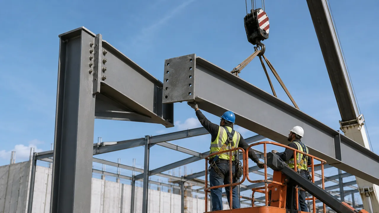
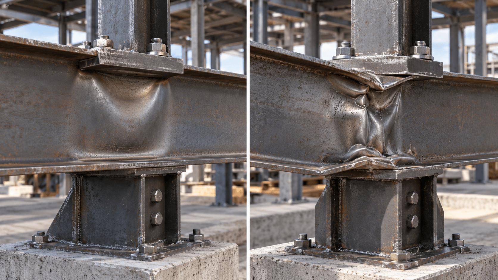
Web damage usually develops close to the concentrated load or support rather than along the entire member.
Possible visual signs include:
- Local crushing near the bearing location
- Out-of-plane deformation of the web
- Wrinkling or buckling close to the flange
- Localized distortion around a support reaction
- Rotation or deformation of the adjacent flange
These signs should not be confused with ordinary beam deflection.
Global deflection usually develops gradually over the span. Local crippling is concentrated within a comparatively short region near the load introduction point.
The exact deformation pattern can vary depending on whether the load is near the end of the beam, within the span, applied through one flange, or transferred through both flanges.
Web Crippling vs Web Local Yielding
Two local limit states that are often considered around concentrated forces are web crippling and web local yielding. They are related because both can occur near supports or concentrated loads, but they describe different structural behavior.
Web local yielding primarily concerns excessive compressive stress causing the steel in the web to reach its yield strength over a localized area.
Web crippling involves local instability and distortion of the web under concentrated force. Bending, compression, web slenderness, restraint, and the location of the applied load can all influence the response.
A beam can therefore require separate checks for both conditions.
Passing a local yielding check does not automatically prove that the web is safe against local crippling. Likewise, a satisfactory crippling capacity does not eliminate the need to evaluate yielding and other relevant limit states.
Web Crippling vs Web Buckling
The term web buckling is sometimes used broadly, but it is useful to distinguish different instability mechanisms.
Web crippling is generally concentrated close to a bearing point or localized force. The deformation occurs within a relatively limited region where the load enters the beam.
Other forms of web buckling may involve a larger portion of the web panel. Shear buckling, for example, is associated with high shear stresses over the web area and should not be treated as the same phenomenon.
Important variables include:
- Web slenderness
- Panel dimensions
- Flange restraint
- Load location
- Presence of transverse stiffeners
- Boundary conditions
Engineers should identify the actual failure mechanism rather than treating every visible web deformation as the same design condition.
Where Web Crippling Commonly Occurs
Understanding typical high-risk locations makes it easier to identify where additional calculations or detailing may be required.
Beam End Supports
At a beam end, the support reaction is transferred through the flange and web into the supporting column, wall, bracket, or bearing surface.
Because there is less web material beyond the load toward the end of the member, end loading can behave differently from loading farther inside the span.
A short bearing length combined with a high reaction can make this region particularly important.
Interior Supports
Continuous beams and girders may develop large reactions over interior columns or supports.
Forces from multiple spans can be transferred through the same region, creating significant local demand. Designers must consider the actual support geometry and bearing arrangement rather than relying only on the beam’s overall shear capacity.
Concentrated Loads on the Top Flange
Mechanical equipment, secondary beams, columns, storage systems, or other structural components may introduce concentrated loads through the top flange.
If the load is applied away from a suitable stiffened point, the web can be subjected to substantial localized stress and deformation.
Heavy loads should therefore be coordinated with the structural framing before fabrication.
Steel Framing Connections
Some steel connections transfer large forces into a relatively limited portion of the web.
Connection plates, brackets, seats, and other details should be designed so that the load path is clear and the local beam components have sufficient resistance.
Factors That Affect Web Crippling Capacity
A number of geometric and loading parameters influence resistance.
| Factor | Effect on Web Crippling |
|---|---|
| Web thickness | A thicker web generally provides greater resistance to local deformation. |
| Web slenderness | More slender webs are generally more sensitive to instability. |
| Bearing length | A longer bearing length spreads the force over a larger area. |
| Distance from beam end | End loading and interior loading can produce different local behavior. |
| Flange restraint | Restraint can influence how the flange and web deform together. |
| Load location | The position and method of load introduction affect the local stress distribution. |
| Steel strength | Material properties influence available resistance but do not eliminate stability considerations. |
| Stiffeners | Properly designed stiffeners can transfer concentrated forces more directly. |
| Section geometry | Flange dimensions, web depth, fillets, and other geometric features affect local behavior. |
No single factor should be evaluated in isolation. The capacity results from the interaction between member geometry, loading, restraint, and connection detailing.
Interior Loading vs End Loading
The location of the concentrated force relative to the beam end can significantly affect local web behavior.
For a load applied well within the beam span, web material exists on both sides of the loaded region. This can provide a different load distribution and restraint condition compared with a reaction applied near the end.
At an end support, the available web area is limited on one side. The stress field therefore develops differently, and the corresponding design provisions may also differ.
Designers should identify the correct loading case before calculating available resistance. Using an interior-loading condition for a beam end reaction can produce an inappropriate result.
How Engineers Check Web Crippling
The detailed equations depend on the applicable structural design standard and member type, but the engineering process generally follows several consistent steps.
Identify the Concentrated Force
The first step is to determine the magnitude of the support reaction or concentrated load.
The calculation should reflect the governing load combinations for the project rather than a simplified service load that may underestimate the design demand.
Determine the Loading Condition
The engineer identifies whether the force acts near the member end or within the span and how it enters the section.
The applicable standard may distinguish between different loading arrangements, including one-flange and two-flange loading conditions.
Check the Web Geometry
Relevant properties may include:
- Web thickness
- Clear web depth
- Flange dimensions
- Fillet or corner geometry
- Bearing length
- Distance to the member end
These dimensions should correspond to the actual section and connection detail.
Calculate the Available Resistance
The appropriate design provisions are then used to calculate the available local web resistance.
There is no single universal equation that should be applied to every steel beam. Hot-rolled beams, welded sections, and cold-formed members can follow different design procedures.
Compare Required and Available Strength
The factored demand is compared with the applicable design resistance.
If the available capacity is insufficient, the engineer may modify the section, bearing detail, stiffening arrangement, or load path.
Web Crippling in Hot-Rolled Beams vs Cold-Formed Steel
The same general concept can occur in both hot-rolled and cold-formed steel members, but their behavior and design provisions should not be assumed to be identical.
Hot-rolled I-shaped beams usually have comparatively thicker webs and substantial flange-to-web transitions. Their local response is influenced by the geometry of the rolled section and its support conditions.
Cold-formed members frequently use much thinner material. Localized bearing behavior can therefore become especially important, and design standards may use equations specifically developed for thin-walled sections.
An equation or design assumption intended for one member category should not be transferred directly to another without verifying that it is permitted by the governing standard.
How to Prevent Web Crippling
When the unstiffened beam web does not provide sufficient capacity, several practical solutions are available.
Increase the Bearing Length
Increasing the bearing length distributes the concentrated reaction over a larger area.
A larger bearing plate or longer seat can reduce localized demand and may improve both yielding and crippling resistance.
Add Bearing Stiffeners
Transverse bearing stiffeners can provide a more direct path for transferring high concentrated forces between the flanges.
They are commonly considered around major reactions, heavy equipment supports, transfer girders, and similar high-demand locations.
Stiffener dimensions, welds, fit, and connection to the flanges must all be properly designed.
Use Bearing Plates
Bearing plates can help spread a concentrated force before it reaches the beam web.
Their effectiveness depends on plate dimensions, thickness, contact conditions, and how the plate interacts with the flange and supporting structure.
Select a Section With a Thicker Web
If local web resistance governs the design repeatedly, selecting a beam with a thicker web may be more practical than adding several complicated stiffeners.
The most economical solution depends on material cost, fabrication labor, repetition, and erection requirements.
Improve Load Placement
Where practical, heavy concentrated loads can be positioned near existing stiffened regions or major support points. Early coordination between structural engineers, equipment designers, and fabricators can prevent loads from being introduced at unfavorable locations.
Modify the Connection Detail
Sometimes the beam itself does not need to change. A revised seat, plate, bracket, or connection geometry may distribute the force more effectively. A clear load path is often more efficient than simply increasing steel tonnage.
When Are Web Stiffeners Required?
Not every steel beam requires bearing stiffeners.
They become relevant when concentrated forces exceed the available resistance of the unstiffened web or when the structural configuration requires a more direct load-transfer mechanism.
Typical situations may include:
- Very high support reactions
- Heavy equipment loads
- Transfer girders
- Crane-supporting structures
- Columns supported on beams
- Large concentrated loads over short bearing lengths
Whether stiffeners are necessary should be determined by calculation.
Adding stiffeners everywhere may unnecessarily increase fabrication time, welding, inspection, coating work, and cost.
Common Web Crippling Design Mistakes
| Common Mistake | Why It Matters |
|---|---|
| Checking bending only | A beam can pass the global flexural check while failing locally near a support or point load. |
| Ignoring large support reactions | Reactions may create critical localized forces in the web. |
| Assuming a local yielding check covers every web limit state | Yielding and local instability are separate mechanisms and may require separate checks. |
| Using insufficient bearing length | A short bearing area increases local stress concentration. |
| Adding equipment after structural design | New concentrated loads may exceed the original local web capacity. |
| Using the wrong loading condition | End loading and interior loading can require different evaluations. |
| Assuming a thicker flange solves the problem | The web may remain the controlling component. |
| Using an equation for the wrong member type | Hot-rolled and cold-formed sections may follow different design provisions. |
Practical Example of a Web Crippling Risk
Consider a steel roof girder carrying several secondary beams.
The girder has sufficient flexural capacity for the total roof load, and its overall shear strength is also adequate. However, one end of the girder transfers a large reaction through a relatively narrow bearing area onto a column.
The reaction is concentrated into a small region of the web.
The engineer therefore evaluates the local web limit states in addition to the global beam checks. If the unstiffened web does not provide adequate resistance, possible solutions include increasing the bearing length, installing transverse stiffeners, modifying the connection, or selecting a section with a thicker web.
This example illustrates why global beam capacity alone cannot confirm the safety of every local detail.
Why Web Crippling Matters in Steel Building Design
Web crippling matters because local forces can govern the design of a beam that otherwise appears more than adequate.
This is particularly relevant in:
- Industrial steel buildings
- Steel warehouses
- Manufacturing plants
- Equipment platforms
- Transfer structures
- Crane-supporting framing
- Heavily loaded floor systems
- Large roof structures
The issue also demonstrates why structural design, connection engineering, fabrication, and erection planning must be coordinated.
A concentrated load shown on the structural drawings must eventually pass through real plates, welds, bolts, flanges, webs, stiffeners, and supporting members. Each component along that load path needs adequate strength and stability.
For XTD Steel Structure, coordinated detailing between engineering and fabrication is especially important when producing large industrial members with heavy reactions or specialized connection requirements.
Final Design Considerations
Web crippling is a localized beam-web failure mechanism associated with concentrated loads and support reactions. It can become critical even when the beam satisfies its overall bending and shear requirements.
A complete design should therefore evaluate the local load path around major reactions and concentrated forces rather than assuming that adequate global beam strength guarantees adequate local performance.
Important considerations include bearing length, web thickness, web slenderness, load position, support condition, flange restraint, stiffeners, connection geometry, and the requirements of the applicable structural design standard.
Where local resistance is insufficient, practical solutions may include increasing the bearing area, adding bearing stiffeners, modifying the connection, relocating the load, or choosing a section with a more suitable web.
When these factors are addressed early, engineers can reduce localized failure risk while avoiding unnecessary increases in overall steel weight.