A steel beam or girder can have adequate overall bending strength and still develop a serious failure in its web. This is especially important near supports, concentrated reactions, equipment loads, transfer connections, and other locations where large forces enter a relatively small region of the member.
The comparison of web crippling vs web buckling is important because the two failure mechanisms can occur in similar areas but do not represent the same structural behavior. Web crippling is generally associated with highly localized compression, deformation, and instability near a concentrated bearing force. Web buckling involves instability of a compressed web region and may affect a larger portion of the web depending on the loading condition, panel geometry, and restraint.
The distinction affects the design check, the parameters that control resistance, and the reinforcement required. Bearing length may have a major influence on web crippling, while web slenderness, unsupported panel dimensions, and restraint become particularly important for buckling. In heavily loaded connections, both limit states may need to be evaluated before the member can be considered adequate.
Web Crippling vs Web Buckling: Main Difference
The main distinction in web crippling vs web buckling is the scale and mechanism of the local instability. Crippling is closely associated with concentrated bearing forces acting through a flange into the web. Buckling is associated with instability of a compressed web region when its geometry, slenderness, and restraint do not provide sufficient stability.
| Comparison Factor | Web Crippling | Web Buckling |
|---|---|---|
| Typical failure location | Near concentrated load or bearing region | Compressed web region or larger web panel |
| Main trigger | Concentrated compressive force | Compression combined with insufficient plate stability |
| Typical deformation | Localized crushing, folding, kinking, or distortion | Out-of-plane instability of the web |
| Important parameters | Bearing length, web thickness, flange geometry, end distance | Web slenderness, panel dimensions, restraint, stiffener spacing |
| Area involved | Highly localized around load introduction | Potentially larger compressed region |
| Typical reinforcement | Bearing stiffeners, increased bearing length, thicker web | Transverse stiffeners, thicker web, improved restraint, smaller panel |
Why These Failure Modes Are Often Confused
Both mechanisms affect the web and can occur near a heavily loaded support. A distorted web around a bearing point may visually appear to have simply “buckled,” even though the governing design limit state is local crippling.
The distinction becomes even more important because structural design standards may separate several stability conditions. For example, the AISC Specification for Structural Steel Buildings distinguishes web local crippling from other web buckling-related limit states rather than treating all local web instability as one condition.
What Is Web Crippling?
Web crippling is a localized failure mechanism caused by concentrated compressive loading transmitted through a flange into the web. High local compression and bending develop near the flange-web junction, and the web can deform before the overall member reaches its global strength.
Local Failure Under Concentrated Compression
When a support reaction or concentrated load acts through a short bearing area, the force must spread from the flange into the relatively thin web.
If the web cannot distribute that force safely, localized deformation can develop. The affected area is generally concentrated close to the bearing point rather than extending across an entire web panel.
Typical Web Crippling Locations
Common locations include:
- Beam ends at columns or bearing walls
- Girder reactions at primary supports
- Secondary beam reactions on primary girders
- Seated beam connections
- Concentrated equipment supports
- Transfer beams and heavily loaded framing intersections
Typical Web Crippling Deformation
The deformation can appear as local folding, kinking, crushing, or distortion near the loaded flange. The flange and the immediately adjacent web interact during this response, which is why flange geometry and bearing length are part of the local behavior.
What Is Web Buckling?
Web buckling occurs when a compressed region of the web becomes unstable and moves out of its original plane. Instead of being controlled only by material strength, the behavior is strongly influenced by plate geometry and restraint.
The term “web buckling” can describe more than one engineering condition. Depending on the force arrangement and member configuration, designers may need to consider sidesway web buckling, compression buckling of the web, or plate-type instability within a web panel.
Instability of a Compressed Web Region
A thin plate can lose stability under compression before the steel reaches its full yielding capacity. The same principle applies to a structural steel web.
As the web becomes deeper and thinner, its plate slenderness increases. If the compressed region does not have sufficient restraint from the flanges, stiffeners, or adjacent structure, out-of-plane deformation can develop.
Localized and Panel-Type Buckling
Some instability may remain close to a support or concentrated load. In other cases, a larger web panel between flanges and transverse stiffeners may participate.
This is one reason web buckling should not be treated as merely another name for web crippling. The effective region and governing geometric parameters can be significantly different.
Typical Locations for Web Buckling
Potentially critical areas include:
- Deep girder support regions
- Thin-web plate girders
- Compression zones near concentrated reactions
- Web panels with large stiffener spacing
- Connections transferring compression through opposing flanges
How the Failure Mechanisms Differ
Stress Distribution in Web Crippling
Web crippling develops from a highly concentrated force entering through the flange. The most severe stresses occur close to the bearing region and flange-web intersection.
Short bearing lengths generally create more concentrated load introduction than longer bearing plates because the same force must be transferred through a smaller area.
Stress Distribution in Web Buckling
Buckling is associated with instability in a compressed web region. The compression may result from a concentrated force, connection action, or another structural load path.
The affected region can extend farther from the initial load point, and its stability depends strongly on web depth, thickness, restraint, and panel geometry.
Difference in Deformation Pattern
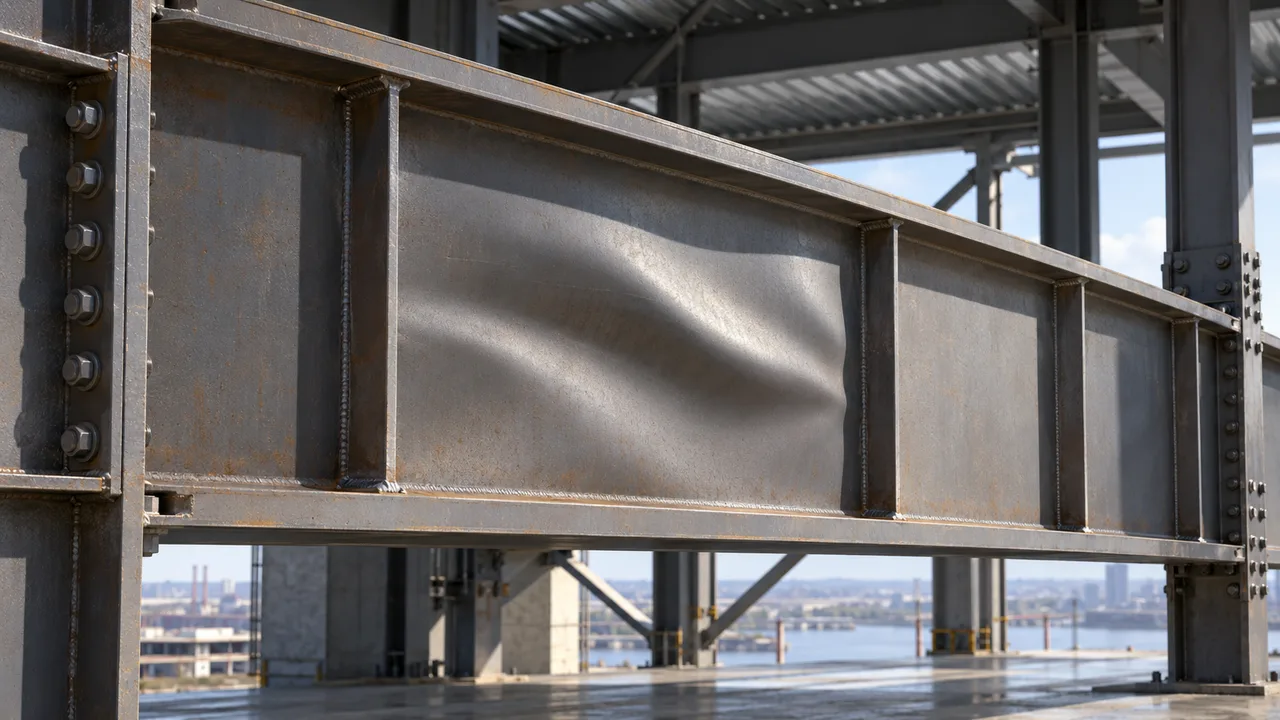
Crippling commonly produces severe local deformation close to the bearing area. Buckling tends to produce a broader out-of-plane wave or displacement of the web.
Actual structural failures may contain characteristics of more than one limit state, which is why visual appearance alone should not replace calculation.
Difference in Effective Web Area
Crippling is strongly controlled by the local area receiving the concentrated force. Buckling can involve a larger portion of the web acting as a plate or compression element.
That difference influences both the design check and the most effective reinforcement strategy.
Loads That Can Cause Web Crippling or Web Buckling
Concentrated Support Reactions
Large support reactions are one of the most common conditions requiring local web checks. The risk increases when the reaction is transferred through a short bearing length into a relatively thin web.
Equipment and Point Loads
Industrial equipment, elevated platforms, process systems, transfer framing, and structural supports can introduce concentrated forces away from conventional beam ends.
These loads should be coordinated before fabrication because adding them later can create new local web demands that were not included in the original design.
High Compression Near Connections
Beam-to-column connections, transfer joints, girder intersections, and other heavily loaded details can create localized compression in the web.
The designer must understand how force passes through the flange, connection plates, stiffeners, and web rather than checking each component independently.
Combined Shear and Compression
The web may also carry substantial shear while transferring concentrated compression. The required design checks depend on the structural configuration and applicable standard, but the complete stress condition should be considered when evaluating the connection region.
Key Parameters in Web Crippling vs Web Buckling
A useful web crippling vs web buckling comparison requires more than checking web thickness. The two mechanisms respond differently to changes in geometry and restraint.
Web Thickness
A thicker web generally improves resistance to both local crippling and instability. It increases the amount of material available to transfer concentrated forces and reduces plate slenderness.
Web Slenderness
Web slenderness is particularly important for buckling. A deep web with relatively small thickness behaves as a more slender plate and can become more sensitive to instability.
Bearing Length
Bearing length is especially important for web crippling because it affects the area over which concentrated force is introduced.
Increasing the bearing length can reduce the severity of the local stress concentration, provided that the bearing plate itself is sufficiently stiff to distribute the load.
Clear Web Depth
Greater clear web depth can increase plate slenderness when thickness remains unchanged. Deep plate girders therefore require careful stability evaluation even when their overall bending capacity is high.
Distance From the Member End
A concentrated force near the end of a beam has different surrounding web restraint from a similar force located farther inside the span.
End reactions therefore require the correct boundary condition when evaluating local web resistance.
Stiffener Spacing
Transverse stiffeners can reduce the dimensions of an unsupported web panel and improve stability. Their spacing may therefore significantly affect buckling behavior.
Flange Restraint
Flanges help distribute concentrated forces and restrain the edges of the web. Their stiffness, connection condition, and lateral restraint influence the local response.
Steel Strength
Higher yield strength can improve some resistance calculations, but buckling strength does not increase in direct proportion to material yield strength because instability is also governed by geometry and stiffness.
Web Crippling Design Checks
Identify the Concentrated Reaction
Determine the governing design reaction or point load and identify the exact location where it enters the member.
Determine the Bearing Length
Use the actual length over which the load is transferred through the flange. Do not assume an effective width that the connection cannot physically provide.
Classify End or Interior Loading
Determine whether the load acts near the member end or at an interior location. The available surrounding web and restraint differ between these conditions.
Calculate Available Crippling Resistance
Use the applicable structural design standard, member dimensions, material properties, bearing geometry, and appropriate resistance or safety factors.
Check Related Limit States
The same concentrated force can also require checks for:
- Web local yielding
- Flange local bending
- Shear
- Connection plate strength
- Stiffener strength
- Weld or bolt capacity
Passing the web crippling check does not prove that the entire connection region is adequate.
Web Buckling Design Checks
Define the Compressed Web Region
Identify the web area participating in the instability check. Depending on the condition, this may involve the region between flanges, between stiffeners, or near opposing concentrated compression forces.
Determine Web Slenderness
Establish the relevant clear web depth, web thickness, and panel dimensions.
A slender web generally has less resistance to out-of-plane instability than a compact web with similar material strength.
Identify the Compression Demand
Determine how the compression enters the web and whether it comes from a bearing reaction, connection force, opposing flange forces, or another structural action.
Evaluate Buckling Resistance
Calculate the applicable web stability resistance using the governing design provisions. The correct buckling model must match the actual force arrangement rather than simply applying a generic plate formula.
Check Boundary Conditions and Restraint
Flange stiffness, lateral restraint, transverse stiffeners, adjacent panels, and connection details can change the effective buckling condition.
Can Web Crippling and Web Buckling Occur Together?
Yes. A heavily loaded support can be susceptible to several local web limit states at the same time.
Shared Support Region
A concentrated reaction can produce intense local compression close to the bearing plate while also generating compression over a larger portion of the web.
The local bearing region may therefore require a crippling check while the surrounding web requires a stability check.
Which Failure Happens First?
The governing mechanism depends on factors including:
- Web thickness
- Web depth
- Bearing length
- Distance from the member end
- Magnitude of the reaction
- Panel dimensions
- Stiffener arrangement
- Flange restraint
There is no universal rule that one mechanism always governs first.
Why Both Checks May Be Required
A member that passes the crippling check does not automatically pass a buckling check. Likewise, adequate web stability does not prove that the concentrated bearing region has sufficient crippling resistance.
The individual applicable limit states should therefore be verified rather than replaced by a single generic “web strength” calculation.
Role of Bearing Stiffeners
How Stiffeners Help Against Web Crippling
Bearing stiffeners can create a more direct path for a concentrated reaction and reduce the amount of force that must be distributed through an unstiffened web region.
How Stiffeners Help Against Web Buckling
Transverse stiffeners can also provide restraint and reduce unsupported web panel dimensions, improving stability.
The same stiffener may therefore contribute to more than one design objective, but each function should be explicitly verified.
Full-Depth vs Partial-Depth Stiffeners
A full-depth stiffener can provide a direct structural path between flanges where the design requires it. Partial-depth stiffeners may provide local reinforcement or stability improvement without serving the same force-transfer function.
The correct configuration depends on the actual load path.
Stiffener Design Checks
The stiffener must itself be designed for relevant conditions such as:
- Compression
- Yielding
- Buckling
- Bearing
- Local plate stability
- Weld transfer
- Fit against the flange where required
Adding steel plates without checking how the forces enter and leave them does not automatically create an adequate reinforcement system.
Bearing Plates and Load Distribution
Increasing Bearing Length
A larger bearing plate can increase load distribution along the flange and reduce localized demand on the web. This can be particularly useful when web crippling controls.
Plate Thickness
The plate must be sufficiently stiff to develop the intended bearing distribution. An excessively flexible plate may bend and concentrate force into only part of the assumed contact area.
Alignment and Contact
Poor alignment, gaps, eccentricity, and incomplete bearing can significantly change the real load path. Fabrication tolerances and erection conditions should therefore be considered in addition to ideal design geometry.
Web Crippling vs Web Buckling in Common Steel Members
Rolled I-Beams
Rolled I-sections typically have defined flange-web geometry and may provide adequate local resistance for many conventional reactions. Large concentrated forces can still require local checks and reinforcement.
Plate Girders
Plate girders frequently use deep, relatively thin webs to achieve efficient global bending performance. This makes web stability particularly important, especially where large reactions or concentrated loads are present.
Transfer Girders
Transfer girders can receive substantial reactions from columns, trusses, or secondary framing. Both highly localized bearing effects and broader web stability may become critical.
Industrial Building Frames
In a large steel structure factory, girder reactions, equipment supports, crane-related framing, secondary beams, and transfer members can introduce substantial concentrated forces into relatively small web regions.
These forces should be coordinated with connection geometry, bearing plates, stiffeners, and fabrication details before production. Retrofitting reinforcement after equipment layouts are finalized can be more difficult than incorporating the required load path during the original design.
Practical Example: Heavily Loaded Girder Support
Consider a deep steel girder with a large end reaction, a relatively thin web, a short bearing plate, and no initial transverse stiffeners.
Web Crippling Check
The designer first identifies the factored reaction, bearing length, web thickness, flange dimensions, and position of the load relative to the girder end.
If available local crippling resistance is lower than the required reaction, the bearing region requires revision.
Web Buckling Check
The designer then evaluates the compressed web region, including web slenderness, panel dimensions, flange restraint, and any transverse stiffener boundaries.
The web may pass the concentrated bearing check but still require improved stability.
Possible Reinforcement
Potential solutions include:
- Increasing bearing plate length
- Installing bearing stiffeners
- Using a thicker web
- Adding transverse stiffeners
- Reducing unsupported web panel dimensions
- Revising how the reaction enters the girder
Recheck the Complete Load Path
After reinforcement is added, the designer must still verify the flange, web, stiffeners, welds, bearing plate, and supporting element.
The objective is not simply to prevent one visible failure mode. The complete concentrated-force load path must have sufficient capacity and stability.
Common Design Mistakes
| Common Mistake | Why It Is a Problem | Better Practice |
|---|---|---|
| Treating crippling and buckling as the same failure | The mechanisms and controlling parameters are different | Check each applicable limit state separately |
| Checking only global beam capacity | Local web failure may govern before flexural capacity | Verify the concentrated-force region |
| Ignoring actual bearing length | Local crippling behavior depends strongly on load introduction | Use the real bearing geometry |
| Ignoring web slenderness | A deep thin web may become unstable | Evaluate web stability and panel dimensions |
| Assuming stiffeners solve every problem | The stiffener or its welds can become the next failure point | Design the complete reinforced load path |
| Adding equipment loads after design | New reactions may overload the original web region | Coordinate concentrated loads before fabrication |
| Considering only steel yield strength | Buckling is strongly influenced by geometry and restraint | Evaluate strength, slenderness, and boundary conditions together |
How to Identify the Governing Web Failure Mode
Signs Web Crippling May Govern
Web crippling deserves particular attention when the design has:
- Very short bearing length
- Large concentrated reaction
- Relatively thin web
- Load close to the member end
- Severe local compression near a flange
Signs Web Buckling May Govern
Buckling becomes increasingly important when the structure has:
- Deep and slender webs
- Large unsupported web panels
- High compression
- Wide stiffener spacing
- Limited edge or lateral restraint
When Both Should Be Checked
Both mechanisms should receive attention in heavily loaded supports, transfer girders, deep plate girders, major industrial structures, and concentrated equipment-support regions.
The applicable design standard and actual structural configuration ultimately determine which individual limit states require verification.
Web Crippling vs Web Buckling Design Checklist
Before finalizing the member or connection region, verify:
- Factored concentrated reaction
- Load position
- Actual bearing length
- Web thickness
- Clear web depth
- Web slenderness
- Web panel dimensions
- Web local yielding
- Web local crippling
- Applicable web buckling limit states
- Shear capacity where relevant
- Flange behavior
- Stiffener strength and stability
- Weld or bolt capacity
- Erection and temporary stability conditions
- Fabrication and inspection access
Selecting the Right Reinforcement for Local Web Failure
The practical difference in web crippling vs web buckling is that the two conditions represent different forms of local web failure and therefore should not automatically receive the same reinforcement solution.
Web crippling is closely associated with highly concentrated force transfer near a bearing region. Increasing bearing length, introducing properly designed bearing stiffeners, or selecting a thicker web can improve this condition.
Web buckling is fundamentally an instability problem. Increasing web thickness, reducing unsupported panel dimensions, adding transverse stiffeners, or improving restraint may be more effective depending on the actual buckling mode.
A heavily loaded connection can require both approaches. Increasing bearing length may improve the concentrated-force condition without fully resolving web instability, while adding a stiffener may improve stability but still require verification of its own strength, welds, and bearing behavior.
For XTD Steel Structure projects, the connection region is evaluated as a complete structural load path so that the web, flanges, stiffeners, bearing components, welds, and supporting frame work together. When the failure mechanism is correctly identified before fabrication, reinforcement can be selected based on actual structural behavior rather than added later as a generic solution.