Bolted end-plate moment connections provide a practical way to transfer beam moments into columns while keeping field erection relatively straightforward. However, the connection cannot be evaluated only by checking bolt strength or end-plate thickness. The supporting column flange must also resist localized forces introduced by the tension-side bolt rows.
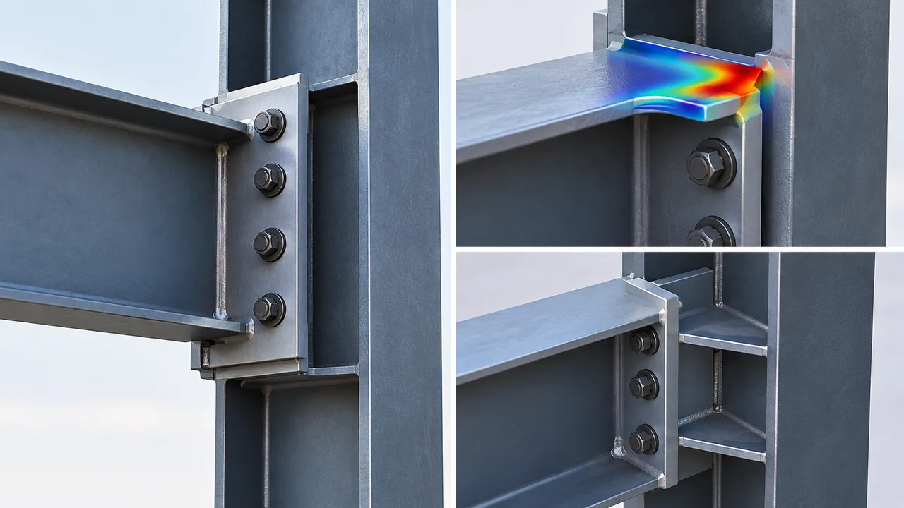
Flange local bending in bolted end-plate connections develops when bolt tension causes the supporting flange to bend locally between the bolt lines, column web, and flange edges. If the flange is too flexible for the applied force, local yielding and excessive deformation can occur even when the column has adequate overall flexural capacity.
For industrial steel structures, this limit state becomes especially important at heavily loaded moment connections, crane-supporting frames, equipment structures, transfer frames, and other locations where large forces are concentrated into relatively compact connection zones.
What Is Flange Local Bending in a Bolted End-Plate Connection?
Flange local bending is a localized flexural response of the supporting column flange caused primarily by tension forces transmitted through the connection bolts. Instead of the entire column section bending as one member, a relatively small portion of the flange deforms around the bolt rows.
The tension bolts pull the end plate toward the supporting column flange. The column web provides restraint near the center of the flange, while the flange outstands provide additional resistance toward the edges. This creates a localized plate-bending mechanism whose strength depends on flange thickness, material properties, bolt location, connection geometry, and the interaction between the connected components.
This behavior should not be confused with overall column bending. A column may easily satisfy its global strength checks while its flange remains vulnerable to a local connection limit state.
How Loads Travel Through a Bolted End-Plate Connection
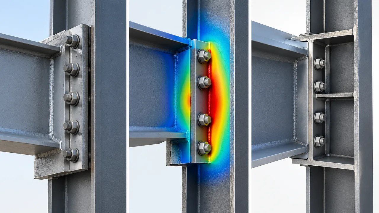
Understanding the load path is fundamental to evaluating local flange behavior. Beam moment is transferred through a combination of tension and compression forces acting near the beam flanges.
On the tension side, the basic load path can be viewed as:
beam flange → weld → end plate → bolts → column flange → column web → column section.
On the compression side, load transfer usually involves bearing and contact between the connected components. The tension side is generally more sensitive to plate flexibility because the bolts must pull the connected plates together while transferring significant tensile force.
A complete bolted end-plate design therefore needs to coordinate bolt strength, end-plate flexure, supporting flange behavior, weld resistance, column web limit states, and any required stiffening rather than treating these components independently.
Why the Column Flange Bends Locally
When tension develops in a bolt row, the bolt applies a concentrated pulling force to the column flange. The flange cannot distribute this force uniformly across its full width. Instead, bending develops in the plate around the bolt and between regions of restraint.
Several geometric relationships influence the resulting deformation. A bolt located farther from the column web may create a longer bending lever arm in the flange. A thin column flange is generally more flexible than a thick one, while closely spaced bolt rows can create interacting local bending patterns.
The result is a localized mechanism rather than uniform bending of the entire flange.
Bolt Row Position
Bolt gage, pitch, edge distance, and distance from the column web influence the effective plate region participating in resistance. Changing the bolt layout can therefore change local flange behavior even when bolt diameter and grade remain unchanged.
Column Flange Thickness
Flange thickness is one of the most important variables controlling local bending resistance. Increasing thickness increases plate flexural resistance and reduces flexibility around the tension bolt rows.
However, simply selecting a heavier column is not always the most economical solution. Stiffening, connection geometry changes, or a revised bolt arrangement may provide a more efficient design depending on the governing limit state.
End-Plate and Bolt Stiffness
The connection behaves as an interacting system. A thicker end plate may reduce end-plate deformation but can transfer a greater proportion of the connection demand into the bolts and supporting column components.
For that reason, increasing the strength of one component does not automatically improve every other limit state in the connection.
Flange Local Bending Versus End-Plate Bending
Column flange local bending and end-plate flexural yielding are closely related but occur in different components. Confusing them can lead to incorrect reinforcement decisions.
| Limit State | Component | Main Action | Typical Concern |
|---|---|---|---|
| Column flange local bending | Column flange | Tension from bolt rows | Local yielding and deformation |
| End-plate flexural yielding | End plate | Plate bending around bolts | Yield-line formation |
| Bolt tension rupture | Connection bolts | Tensile force | Insufficient bolt tensile strength |
| Column web local yielding | Column web | Concentrated flange force | Localized web yielding |
| Panel-zone shear | Column web panel | Joint shear | Excessive panel-zone deformation |
The designer must determine which component and limit state governs rather than assuming that visible plate deformation always represents the same failure mechanism.
Prying Action and Its Effect on Flange Bending
Plate flexibility can also produce prying action. As a plate bends between its supported region and bolt line, contact forces can develop in a way that increases tension in the bolts beyond the force obtained from a simple direct-load calculation.
Prying behavior depends on plate thickness, bolt stiffness, bolt position, edge distance, material strength, and connection geometry. A flexible plate can therefore change both the bolt force and the local plate-bending demand.
This interaction is one reason bolted tension components should be evaluated as systems instead of assuming that the nominal beam flange force is divided directly among the bolts without additional effects.
Research published through the AISC Engineering Journal discusses yield-line methods for local flange bending together with the effect of prying action on bolted flange connections.
Yield-Line Behavior Around Bolt Rows
When a plate approaches its flexural resistance, yielding may develop along characteristic lines surrounding the bolt rows and restrained regions. These yield lines form a mechanism that represents how the plate redistributes bending before reaching its local strength limit.
The exact mechanism depends strongly on connection geometry. Bolt spacing, edge distance, flange width, distance to the web, stiffener arrangement, and the position of adjacent bolt rows can all influence the effective yield-line pattern.
Because of this geometry dependency, designers should avoid applying one simplified local plate equation indiscriminately to every bolted end-plate configuration. Design procedures should reflect the specific connection type and applicable structural design standard.
Key Variables in Flange Local Bending Checks
Several variables should be coordinated when evaluating flange local bending in bolted end-plate connections.
Flange Thickness
A thicker flange provides greater flexural resistance around the tension bolt rows and generally reduces local deformation.
Flange Yield Strength
Higher yield strength increases available plate resistance, although material strength does not eliminate the effects of geometry or plate flexibility.
Bolt Diameter and Strength
Larger or stronger bolts can increase bolt capacity, but they may also permit greater forces to be transferred into the supporting flange. Improving bolt capacity alone does not guarantee adequate flange performance.
Bolt Gage and Pitch
Bolt spacing changes the effective plate geometry and influences how local bending mechanisms develop between adjacent bolts, the column web, and flange edges.
Distance From the Bolt Row to the Column Web
This distance affects the local bending span of the flange. Greater distance can increase flange flexibility and change the governing yield-line mechanism.
End-Plate Thickness
End-plate thickness affects the distribution of deformation and the interaction between plate bending, bolt tension, and supporting flange response.
Connection Stiffeners and Continuity Plates
Stiffeners or continuity plates can redirect concentrated flange forces toward the column web and reduce demand on an otherwise flexible column flange.
When Column Stiffeners or Continuity Plates May Be Required
If the supporting flange does not provide sufficient local resistance, several design responses are possible. The designer may select a column with a thicker flange, revise bolt geometry, reduce connection demand, or provide continuity plates or other reinforcement.
Continuity plates can create a more direct load path from the beam flange region through the column section. They are particularly useful when large tension or compression forces must be transferred through a column whose unstiffened flange or web does not provide adequate local capacity.
Reinforcement should not be added automatically. The governing limit state must first be identified. A plate intended to solve column flange bending will not necessarily resolve bolt rupture, column web yielding, panel-zone shear, or inadequate weld strength.
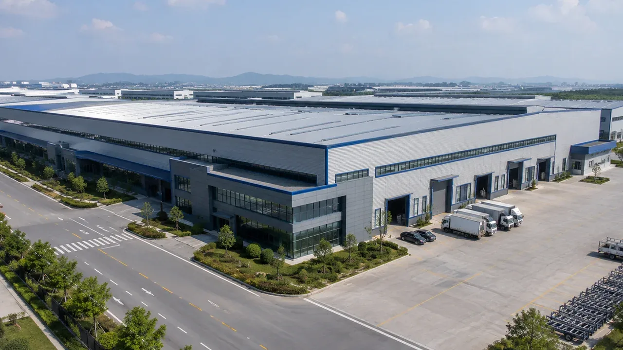
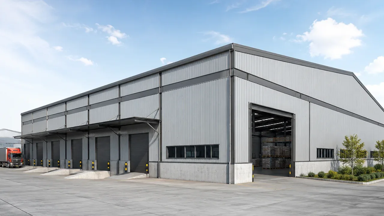
Flange Local Bending in a Steel Structure Factory
A steel structure factory often contains more highly loaded moment connections than a simple storage building. Crane frames, heavy equipment platforms, production mezzanines, pipe-support structures, transfer framing, and large-span industrial roofs can all generate significant connection forces.
For example, a moment-resisting frame supporting crane operations may be subjected to vertical, lateral, and dynamic actions. Equipment-support frames can also introduce large concentrated forces through relatively small connection regions.
In these situations, connection detailing must consider not only the member forces from the structural analysis but also how those forces physically move through bolts, plates, welds, column flanges, and webs.
Fabrication and Erection Factors That Affect Connection Performance
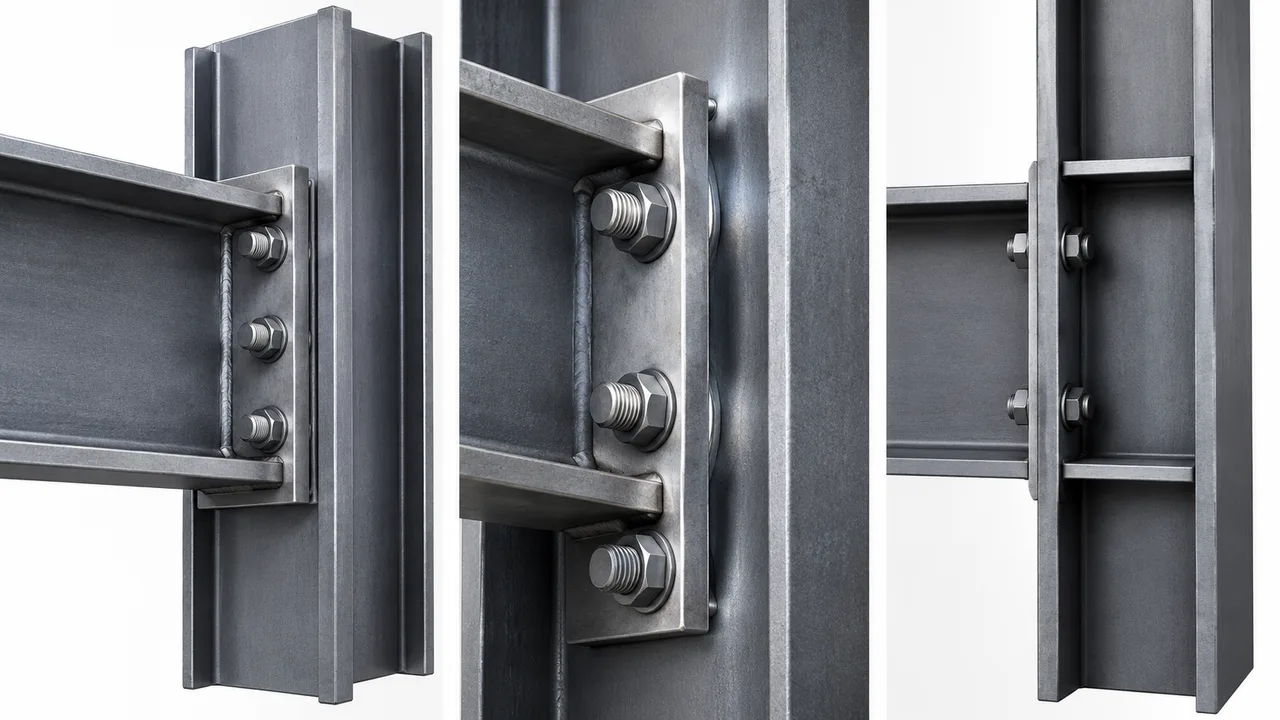
Connection behavior depends on fabrication accuracy as well as structural calculations. End plates should be fabricated with appropriate flatness, bolt holes must align with the supporting member, and welding distortion should be controlled.
Poor fit-up can create unintended gaps between the end plate and column flange. Misalignment may also produce eccentric loading that was not included in the design model.
Bolt installation is equally important. Bolt type, installation procedure, hole condition, and access must correspond to the connection specification. Where continuity plates or stiffeners are required, their position and weld details should match the calculated load path.
Common Design Mistakes
One common mistake is checking bolt tensile strength while ignoring the flexibility of the supporting column flange. A strong bolt does not guarantee that the plate receiving the bolt force has adequate resistance.
Another mistake is treating column flange local bending and end-plate bending as interchangeable conditions. They involve different plates and may require different solutions.
Designers should also avoid assuming that larger bolts automatically improve the connection. Higher bolt resistance can shift the governing demand to the end plate, column flange, weld, or column web.
Ignoring prying action where it is relevant can underestimate bolt demand, while adding stiffeners without identifying the governing limit state may increase fabrication cost without addressing the actual weakness.
Finally, calculation geometry must match shop drawings. Changes in bolt spacing, plate dimensions, or stiffener locations can alter local connection behavior.
How XTD Steel Structure Coordinates End-Plate Connections
Industrial steel connections require coordination between structural analysis, connection design, shop detailing, fabrication, and erection. XTD Steel Structure coordinates bolt layouts, plate thicknesses, weld details, local column reinforcement, fabrication tolerances, and inspection requirements so that the connection shown on the shop drawing represents the intended structural load path.
This coordination is especially important for factory buildings, crane-supporting structures, large-span industrial frames, and other projects where localized connection forces can control otherwise efficient steel members.
Practical Design Takeaway for Flange Local Bending
Reliable flange local bending in bolted end-plate connections design begins with the complete load path rather than a single component check.
The beam flange, end plate, bolts, supporting column flange, column web, welds, and any reinforcement interact as a connection system. Increasing the strength of one component may simply transfer the governing demand to another.
The most effective design therefore identifies the controlling local limit state first and then selects the appropriate response, whether that involves changing plate thickness, modifying bolt geometry, selecting a different column section, or introducing properly detailed stiffeners.
FAQ About Flange Local Bending in Bolted End-Plate Connections
What Causes Flange Local Bending in Bolted End-Plate Connections?
It is primarily caused by concentrated tension forces from the connection bolts acting on the supporting column flange. These forces produce localized plate bending between the bolt rows, column web, flange edges, and other restrained regions.
Is Column Flange Local Bending the Same as End-Plate Bending?
No. Column flange local bending occurs in the supporting column flange, while end-plate bending occurs in the plate welded to the beam. Both can develop in the same connection, but they are separate limit states and must be evaluated accordingly.
How Does Prying Action Affect an End-Plate Connection?
Prying action can increase bolt tension when deformation of the connected plates produces additional contact forces. Its significance depends on plate stiffness, bolt stiffness, bolt position, edge distance, and connection geometry.
When Are Column Stiffeners Needed in a Bolted End-Plate Connection?
Stiffeners or continuity plates may be required when the unstiffened column flange or web cannot safely transfer the concentrated connection forces. Their necessity should be determined from the governing connection limit state rather than assumed for every moment connection.