A steel beam can have sufficient strength and still perform poorly if its connection allows excessive rotation, concentrates force in a thin plate, or transfers loads into an inadequately reinforced column. For this reason, bolted end-plate design must be treated as a complete connection system rather than a simple selection of bolts and plate thickness.
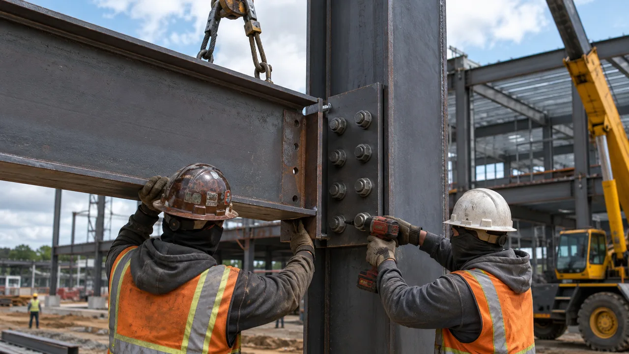
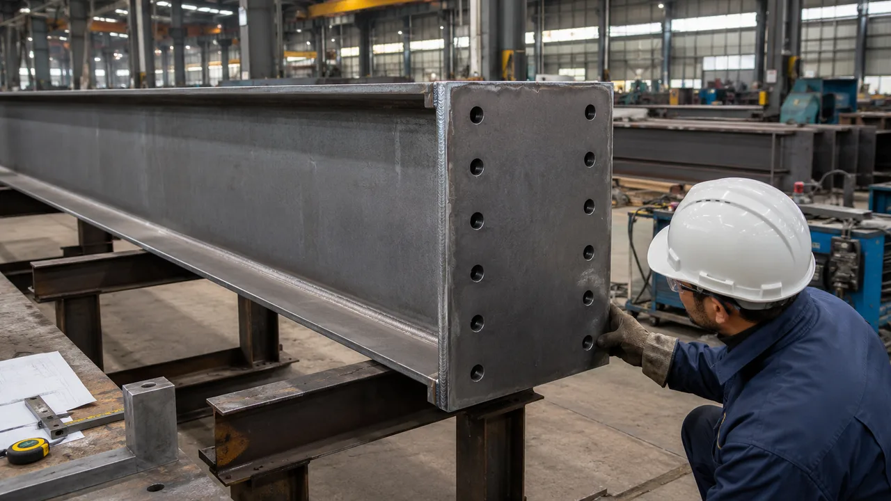
A typical end-plate connection includes a steel plate welded to the end of a beam, rafter, or girder. The fabricated member is then connected to another beam or column with high-strength bolts during site erection. Depending on its configuration, the connection can transfer shear, axial force, bending moment, or a combination of these actions.
Successful performance depends on the interaction between bolts, end-plate bending, welds, beam flanges, beam webs, supporting column components, stiffeners, fabrication tolerances, and erection conditions. The connection must also provide the stiffness, ductility, deformation capacity, and constructability required by the overall structural system.
What Is Bolted End-Plate Design?
Bolted end-plate design is the engineering process used to determine the geometry, resistance, stiffness, and detailing of an end-plate connection. The objective is to create a clear load path from the connected beam into the supporting member without allowing any individual component to reach an unacceptable limit state.
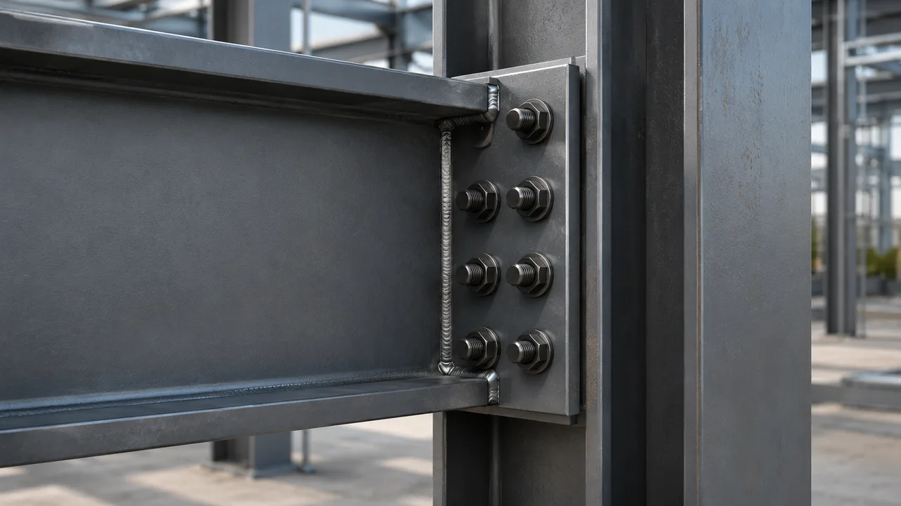
A basic beam-to-column configuration normally contains:
- A structural steel beam or rafter
- An end plate welded to the beam end
- High-strength bolts passing through the end plate and supporting flange
- Beam flange welds that transfer tensile and compressive forces
- A beam web weld that transfers shear and other local forces
- A supporting column flange and web
- Optional end-plate stiffeners, continuity plates, or web stiffeners
The plate-and-beam assembly is normally completed in the fabrication shop. At the construction site, the member can be positioned, temporarily secured, aligned, and permanently bolted without extensive field welding.
Common Applications
End-plate connections are widely used in:
- Beam-to-column moment connections
- Beam-to-beam connections
- Portal frame eaves and apex joints
- Rafter and girder splices
- Multi-storey steel buildings
- Industrial platforms
- Equipment-supporting structures
- Roof trusses and transfer structures
- Structures divided into transportable sections
The same general appearance can produce very different structural behavior. One end plate may be designed as a nominally pinned shear connection, while another may be required to develop substantial moment resistance and rotational stiffness.
Main Types of Bolted End-Plate Connections
Flush End-Plate Connection
A flush end plate remains within the overall depth of the connected beam. Bolt rows are positioned between the beam flanges, creating a compact connection that is often suitable for shear-dominant joints, beam splices, and moderate moment demand.
Its advantages include simpler plate cutting, reduced overall connection depth, and fewer conflicts with floors or architectural components. However, the limited distance between the tension and compression zones restricts the available moment-resisting lever arm.
Extended End-Plate Connection
An extended end plate projects beyond one or both beam flanges. This allows additional bolt rows to be positioned outside the beam depth and increases the distance between the tension bolts and the compression zone.
Extended end plates are frequently used where higher moment resistance is required. They may be designed as unstiffened or stiffened connections.
Unstiffened Extended End Plate
An unstiffened configuration uses the end plate without additional triangular or rectangular stiffeners between the plate and beam flange. It is usually faster to fabricate and requires fewer welds.
The plate must have sufficient strength and stiffness to control bending and prying forces. For high moment demand, the required plate thickness or bolt size may become uneconomical.
Stiffened Extended End Plate
A stiffened connection includes steel stiffeners that improve force transfer between the beam flange and the extended portion of the end plate. Stiffeners can reduce local plate deformation and allow the connection to resist higher tensile flange forces.
However, they also increase cutting, fitting, welding, inspection, and coating work. A stiffened detail should therefore be selected because the calculations require it, not simply because it appears stronger.
Information Required Before Design
Before beginning the connection calculations, the designer must understand the forces, connected members, required joint behavior, and project-specific construction conditions.
Design Forces
The connection should be checked for all governing load combinations, including:
- Shear force
- Bending moment
- Axial tension or compression
- Torsion where applicable
- Wind-induced force reversal
- Seismic actions
- Fatigue-producing cyclic loads
- Temporary erection loads
The combination producing the maximum moment may not produce the maximum bolt tension, plate deformation, panel-zone shear, or supporting-member demand. Multiple combinations may therefore govern different connection components.
Connected Member Properties
Required member information includes beam depth, flange width, flange thickness, web thickness, column flange thickness, column web thickness, steel grade, member orientation, and the available space around the joint.
The designer should also check column fillets, beam root radii, floor slabs, cladding supports, service routes, and equipment clearances that may interfere with the plate or bolt arrangement.
Required Connection Behavior
The joint must be consistent with the assumptions used in the global structural analysis. Important requirements include:
- Moment resistance
- Rotational stiffness
- Rotation capacity
- Allowable deformation
- Slip resistance
- Ductility
- Whether the connection must develop the connected member capacity
A connection assumed to be rigid in the frame model should not be detailed as a flexible plate-and-bolt assembly without checking its actual rotational response.
Understanding the Connection Load Path
A clear load path is essential to reliable bolted end-plate design. The designer must understand how forces move through each connection component.
Moment Transfer
Bending moment is generally resisted by a force couple. One beam flange develops tension while the opposite flange transfers compression. The tensile flange force is transmitted through the flange weld, end plate, tension bolt rows, and supporting column flange.
The compression force may be transferred through direct bearing between the end plate and supporting flange or through a combination of contact and weld action. These forces then enter the column flange, web, panel zone, and surrounding frame.
Shear Transfer
Shear can be transferred through bolt shear, bolt-hole bearing, friction in a slip-resistant joint, end-plate bearing, and the beam web weld.
Where bolts resist both shear and tension, the interaction between the two actions must be checked. Bolt threads, hole type, slip requirements, and the number of shear planes can all affect available resistance.
Axial Force Transfer
Axial tension can increase the forces in several bolt rows and change the distribution created by bending moment. Axial compression may increase contact pressure between the end plate and supporting flange.
The connection should therefore be checked for the combined effects of moment, shear, and axial force rather than treating each action independently.
Critical Bolted End-Plate Design Checks
End-Plate Bending and Yielding
The end plate bends between the beam flange, tension bolts, and supporting surface. Its behavior depends on plate thickness, bolt spacing, plate width, edge distances, bolt-row location, and whether stiffeners are present.
A plate that is too thin may undergo excessive deformation before the bolts reach their nominal tensile resistance. This deformation can reduce connection stiffness and generate additional prying forces.
Increasing bolt diameter alone does not correct a connection governed by plate bending. The plate, bolts, and supporting flange must be designed as interacting components.
Bolt Tension Resistance
Tension bolts may be subjected to:
- Direct axial tension
- Tension caused by bending moment
- Additional force from prying action
- Cyclic tension caused by load reversal
- Combined tension and shear
Bolt forces are not always distributed evenly among all rows. Their distribution depends on distance from the compression zone and the relative stiffness of the bolts, plate, and supporting flange.
Prying Action
Prying action develops when a flexible end plate bends and bears against the supporting surface outside or near a tension bolt. This local contact creates an additional force that increases bolt tension beyond the force predicted from the global bending moment alone.
Prying becomes more significant when:
- The end plate is relatively thin
- The distance between the bolt and beam flange is large
- The plate projection beyond the bolt is substantial
- The supporting flange is flexible
- The connection is subjected to high tensile force
Ignoring prying action can result in bolt overload even when the initial bolt calculation appears adequate.
Bolt Shear and Tension Interaction
Bolts carrying both tension and shear must satisfy the interaction requirements of the applicable design standard. The designer should confirm whether the connection is bearing-type or slip-resistant and whether bolt pretension is required.
Slip-resistant connections may be needed when movement could affect alignment, fatigue performance, cladding, machinery, or structural serviceability.
Bolt-Hole Bearing and Tear-Out
Bearing and tear-out must be checked in the end plate and supporting flange. Resistance depends on material strength, plate thickness, bolt diameter, hole type, bolt spacing, edge distance, and load direction.
Insufficient spacing can also produce block shear, in which a group of material around several bolts tears away through a combination of tension and shear.
Net-Section Rupture
Bolt holes reduce the effective plate area. The remaining net section must have sufficient tensile resistance, particularly across critical rows containing several holes.
Large holes, closely spaced bolts, thin plates, or narrow plate widths can reduce net-section resistance considerably.
Weld Resistance
The welds connecting the beam to the end plate must transfer the actual flange, web, axial, and local forces.
The design should consider:
- Beam flange-to-end-plate welds
- Beam web-to-end-plate welds
- Stiffener welds
- Weld throat and effective length
- Base-metal resistance
- Combined stress
- Weld access and inspection
Oversized welds do not automatically improve the connection. Excessive welding can increase heat input, distortion, fabrication time, and residual stress.
Selecting End-Plate Dimensions
Plate Thickness
Plate thickness affects bending resistance, rotational stiffness, prying action, welding distortion, weight, and cost.
A thicker plate generally reduces deformation and prying but can transfer higher forces into the bolts, welds, and supporting column. The final thickness should result from a balanced evaluation of all connection components.
Plate Width
The plate must be wide enough to provide required bolt edge distances, washer clearance, tool access, and load distribution. At the same time, it must fit within the available supporting flange width.
The designer should avoid positioning bolts too close to column flange edges or member fillets.
Plate Height and Extension
Plate height is influenced by the number of bolt rows, beam depth, required moment lever arm, flange clearance, and whether the plate extends beyond the tension flange.
An extended plate may improve moment resistance, but it can conflict with floor slabs, roof sheeting, cladding supports, or nearby structural members.
Bolt Selection and Arrangement
Bolt Grade and Diameter
Bolt selection should consider tension resistance, shear resistance, availability, installation equipment, plate thickness, hole size, and supporting-member capacity.
Very large bolts may require thicker plates, greater spacing, heavier tools, and larger supporting flanges. Standardizing one practical bolt size across repetitive connections can sometimes reduce total fabrication and erection cost.
Bolt Rows, Spacing, and Edge Distance
Adding bolt rows can increase connection resistance, but it also increases plate height and may create uneven force distribution.
The arrangement must provide:
- Code-compliant bolt spacing
- Adequate edge distance
- Clearance for washers and nuts
- Access for tightening equipment
- Space around welds and member fillets
- Acceptable tear-out and block-shear resistance
A detail that works in a calculation model may still be unsuitable if workers cannot position or tighten the bolts.
Pretensioned Bolts and Hole Types
Pretensioned bolts may be required for slip-resistant joints, seismic applications, fatigue-sensitive structures, vibration, load reversal, or project-specific specifications.
Standard holes normally provide more predictable bearing and slip behavior. Oversized or slotted holes can improve erection tolerance but may require special washers, controlled slot orientation, or slip-resistant design.
Supporting Column and Beam Checks
A strong end plate and bolt group can still fail if the supporting member is not checked.
Column Flange Bending
Tension bolt rows pull on the column flange and may cause local bending. Resistance depends on flange thickness, bolt-row position, distance from the column web, and interaction between adjacent rows.
Continuity plates or other reinforcement may be required when the column flange alone cannot transfer the tensile and compressive beam-flange forces.
Column Web Limit States
The supporting column web should be checked for:
- Local yielding
- Web crippling
- Local buckling
- Panel-zone shear
- Concentrated compression
Doubler plates or web stiffeners may be necessary, but they add significant welding, inspection, coating, and fabrication work. Selecting a heavier column section can sometimes be more economical than extensively reinforcing a lighter section.
Supporting Beam Checks
For beam-to-beam end-plate connections, the supporting beam may experience flange bending, web yielding, web crippling, local torsion, or eccentric loading.
Temporary erection stability should also be evaluated because the supporting beam may not receive its full lateral restraint until additional framing is installed.
Connection Stiffness and Serviceability
Connection resistance alone does not determine performance. Plate bending, bolt elongation, column flange deformation, panel-zone shear, and local slip all contribute to joint rotation.
A connection may be strong enough to resist the factored loads but too flexible for the frame assumptions, floor alignment, cladding, machinery, or serviceability limits.
The structural model should classify the joint consistently as:
- Nominally pinned
- Semi-rigid
- Rigid or fully restrained
Where connection rotation materially affects frame drift, member moments, stability, or second-order behavior, the actual joint stiffness should be incorporated into the analysis.
Stiffened vs Unstiffened End Plates
| Design Factor | Unstiffened End Plate | Stiffened End Plate |
|---|---|---|
| Fabrication complexity | Lower | Higher |
| Number of welded components | Fewer | More |
| Typical moment capacity | Moderate | Potentially higher |
| Plate deformation | May be greater | Usually better controlled |
| Welding time | Lower | Higher |
| Inspection requirements | Simpler | More extensive |
| Typical use | Moderate connection demand | Higher moment demand |
A stiffened plate should not be the automatic choice for every moment connection. Where an unstiffened configuration satisfies resistance, stiffness, ductility, and deformation requirements, it may provide faster and more economical fabrication.
Seismic, Cyclic, and Fatigue Considerations
Connections subjected to seismic or cyclic loading require more than static strength. They may need sufficient rotation capacity, controlled yielding, reliable bolt behavior, appropriate weld toughness, and protection against brittle failure.
In a seismic moment frame, load reversal changes which beam flange is in tension. Bolt rows, welds, the column flange, and the panel zone must be capable of resisting forces in both directions.
Where a prequalified connection is required, the designer must follow the permitted configuration, member sizes, material grades, plate dimensions, bolt layout, weld details, and reinforcement requirements. Altering a qualified detail without proper verification can invalidate its expected performance.
Fatigue should also be considered for crane structures, machinery platforms, bridges, vibrating equipment, and industrial facilities exposed to repeated loading.
Fabrication Considerations
Plate Cutting and Drilling
CNC cutting and drilling can improve repeatability, but dimensional control remains essential. Bolt holes must align with the supporting member, plate edges should be clean, and burrs should be removed.
The fabricator should verify plate flatness, hole position, beam-end squareness, and the distance between bolt rows.
Welding Sequence and Distortion
Welding the beam flanges and web to the end plate can cause plate warping or beam-end distortion. Balanced welding sequences, suitable fixtures, controlled heat input, and dimensional checks help maintain alignment.
Large stiffeners and heavy flange welds can increase restraint and residual stress. The welding procedure should reflect material thickness, steel grade, joint preparation, and inspection requirements.
Trial Assembly and Surface Treatment
Trial assembly may be useful for large splices, portal frame members, or repetitive connections with tight tolerances. It can confirm hole alignment, plate contact, orientation, and overall geometry before components reach the site.
Coating specifications should address:
- Shop primer
- Galvanizing
- Slip-critical faying surfaces
- Masking requirements
- Field repair of damaged coating
- Corrosion risk between contacting plates
Transportation and Site Installation
End-plate splices allow long beams, rafters, trusses, and portal frame members to be divided into transportable sections. Splice positions should be selected based on structural forces, transport limits, lifting behavior, and site access.
During erection, the site team must manage beam length tolerances, column position, plate flatness, bolt-hole alignment, and cumulative dimensional error.
Bolt installation requirements may include snug-tightening or a specified pretensioning method. The contractor should confirm bolt grade, washer arrangement, tightening sequence, tool calibration, access, and inspection procedure.
Temporary stability is equally important. A connection may resist the permanent design forces but remain unstable before adjacent framing, purlins, floor beams, or permanent bracing are installed.
Inspection and Quality Control
Shop Inspection
Shop quality control should verify:
- Plate thickness and dimensions
- Bolt-hole size and location
- Beam and plate alignment
- Weld size and continuity
- Welding distortion
- Steel grade and material traceability
- Surface preparation and coating
Site Inspection
Site inspection should confirm:
- Correct bolt grade and diameter
- Correct washers and nuts
- Complete bolt installation
- Required tightening method
- Plate contact and alignment
- Absence of prohibited field modifications
- Repair of damaged protective coatings
Nondestructive testing may be specified for critical welds. Material certificates, bolt certificates, welding records, inspection reports, repair records, and nonconformance reports should be retained as part of the project documentation.
Bolted End-Plate vs Welded Connection
The choice between a bolted end-plate vs welded connection should be based on structural demand, fabrication capability, site conditions, inspection requirements, and total installed cost.
| Selection Factor | Bolted End-Plate Connection | Site-Welded Connection |
|---|---|---|
| Shop fabrication | Requires plate preparation, drilling, and shop welding | May require simpler shop components |
| Site erection | Generally supports faster bolted assembly | Requires more field welding work |
| Weather sensitivity | Lower during bolt installation | Higher during field welding |
| Inspection | Bolt, fit-up, and tightening inspection | More extensive weld inspection may be required |
| Erection tolerance | Can provide limited adjustment through hole detailing | Alignment must be controlled before welding |
| Site equipment | Torque or bolt-tensioning tools | Welding machines, consumables, and weather protection |
| Hot-work risk | Lower at the site | Higher because of field welding |
| Future disassembly | Potentially possible | Generally difficult |
| Connection stiffness | Depends on plate, bolt, and supporting-member behavior | Depends on weld and member detailing |
| Total cost | Project-dependent | Project-dependent |
Neither connection type is universally better. Bolted end plates often provide advantages where repetitive shop fabrication, fast site erection, reduced hot work, and transportable member lengths are important. Site-welded connections may remain suitable where bolt access is restricted, compact geometry is required, or local fabrication practices favor field welding.
Cost Factors in Bolted End-Plate Design
Connection cost is affected by:
- End-plate dimensions and thickness
- Bolt grade, diameter, and quantity
- Number of drilled holes
- Stiffeners
- Weld volume
- Column reinforcement
- Trial assembly
- Protective coating
- Transportation
- Site tightening
- Inspection and testing
- Risk of rework
The lightest connection is not always the least expensive. A slightly heavier detail using repetitive plates, standard bolt sizes, accessible welds, and minimal reinforcement may be faster to manufacture and install.
Early coordination between the structural engineer, connection designer, steel fabricator, and erection contractor allows XTD Steel Structure to evaluate both structural efficiency and practical production requirements.
Common Bolted End-Plate Design Mistakes
| Common Mistake | Possible Consequence | Better Approach |
|---|---|---|
| Designing only for shear | Inadequate moment or axial resistance | Use the complete set of connection forces |
| Ignoring prying action | Excessive bolt tension | Evaluate plate deformation and additional bolt force |
| Selecting an excessively thin plate | High deformation and low stiffness | Check plate strength and serviceability |
| Increasing bolt size without checking the plate | Plate failure may still govern | Design the bolts and plate as one system |
| Ignoring the column flange and web | Supporting-member failure | Check all relevant column-side limit states |
| Providing inadequate bolt access | Installation delays or incomplete tightening | Verify hand and tool clearances |
| Using excessive weld sizes | Distortion and unnecessary cost | Optimize weld size and geometry |
| Adding unnecessary stiffeners | Higher fabrication and inspection cost | Add reinforcement only when required |
| Ignoring erection tolerances | Bolt holes may not align | Coordinate shop and site tolerances |
| Changing a qualified seismic detail | Unverified cyclic performance | Follow the approved configuration |
Practical Bolted End-Plate Design Workflow
- Determine the structural function and location of the connection.
- Extract all governing forces from the structural analysis.
- Define the required resistance, stiffness, rotation, and ductility.
- Select a flush, extended, stiffened, or unstiffened configuration.
- Establish preliminary plate dimensions and bolt geometry.
- Check bolt tension, shear, bearing, and interaction.
- Evaluate prying action and force distribution between bolt rows.
- Check end-plate bending, net-section rupture, tear-out, and block shear.
- Design the beam flange, web, and stiffener welds.
- Check the supporting column or beam.
- Add continuity plates, doubler plates, or stiffeners only where required.
- Verify rotational stiffness and serviceability.
- Review seismic, fatigue, fire, and corrosion requirements.
- Confirm fabrication, transport, erection, and tightening access.
- Complete detailed drawings and inspection requirements.
When Should a Bolted End-Plate Connection Be Used?
A bolted end-plate connection may be suitable when:
- Fast site erection is important
- Shop welding is preferred over field welding
- Members must be divided for transportation
- Moment transfer is required
- Repetitive connections can be standardized
- Site hot work should be minimized
- Future dismantling may be beneficial
- Reliable bolt installation and inspection are available
It may be less suitable when bolt access is severely restricted, the supporting flange is too narrow, connection depth is limited, fabrication tolerances cannot be controlled, or the environment creates a high corrosion risk between contacting plates.
Frequently Asked Questions
What Controls the Thickness of an End Plate?
End-plate thickness is controlled by plate bending, prying action, connection stiffness, bolt arrangement, material strength, required moment resistance, and allowable deformation. The plate must be evaluated together with the bolts and supporting flange.
Can a Bolted End Plate Transfer Both Shear and Moment?
Yes. A properly designed end-plate connection can transfer shear, moment, axial force, or combined actions. Its capacity depends on the plate geometry, bolt group, welds, connected members, and supporting-member resistance.
What Causes Prying Action?
Prying action is caused by deformation of the end plate or supporting flange near a tension bolt. Local contact creates an additional reaction that increases the force in the bolt.
Are Thicker End Plates Always Better?
No. A thicker plate generally reduces deformation but may increase weight, welding demand, material cost, and force transferred into the supporting column. The objective is a balanced connection rather than the thickest possible plate.
When Are End-Plate Stiffeners Required?
Stiffeners may be required when the unstiffened plate cannot provide sufficient resistance, stiffness, or force transfer. Their need should be confirmed through connection calculations.
Can Bolted End Plates Be Used in Seismic Frames?
They can be used when the connection configuration, materials, bolts, welds, member sizes, detailing, and qualification requirements comply with the applicable seismic design provisions.
What Should Be Inspected During Installation?
Inspection should verify bolt grade, diameter, washers, hole alignment, plate contact, tightening method, missing bolts, coating damage, and the condition of the supporting member.
Final Considerations for Steel Structure Projects
Reliable bolted end-plate design requires more than confirming the nominal strength of a bolt group. The end plate, bolts, welds, beam components, supporting column or beam, stiffeners, bracing, fabrication process, and erection sequence influence one another.
The final connection must provide adequate resistance while also controlling deformation, rotation, slip, brittle failure, fatigue, and installation risk. It should be possible to manufacture accurately, transport safely, assemble efficiently, tighten correctly, and inspect without unnecessary difficulty.
Early coordination among structural engineers, connection designers, fabricators, contractors, and inspectors helps reduce rework and produces a connection that performs as intended throughout the service life of the steel structure.