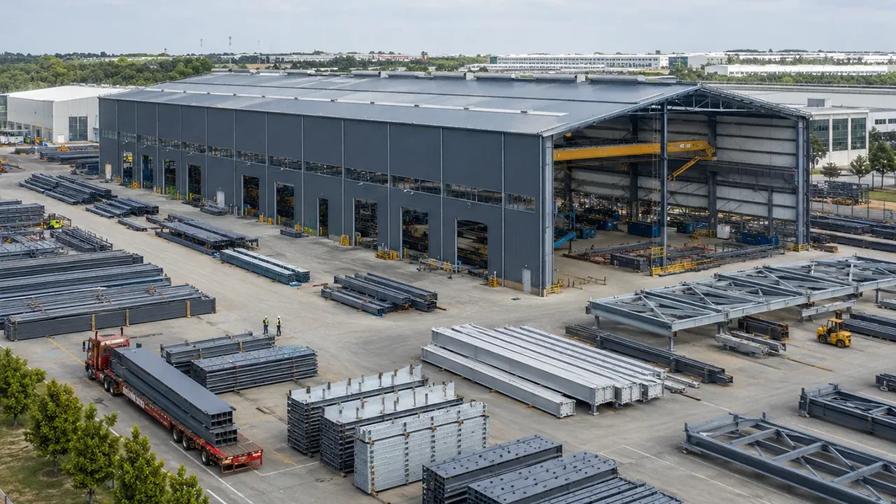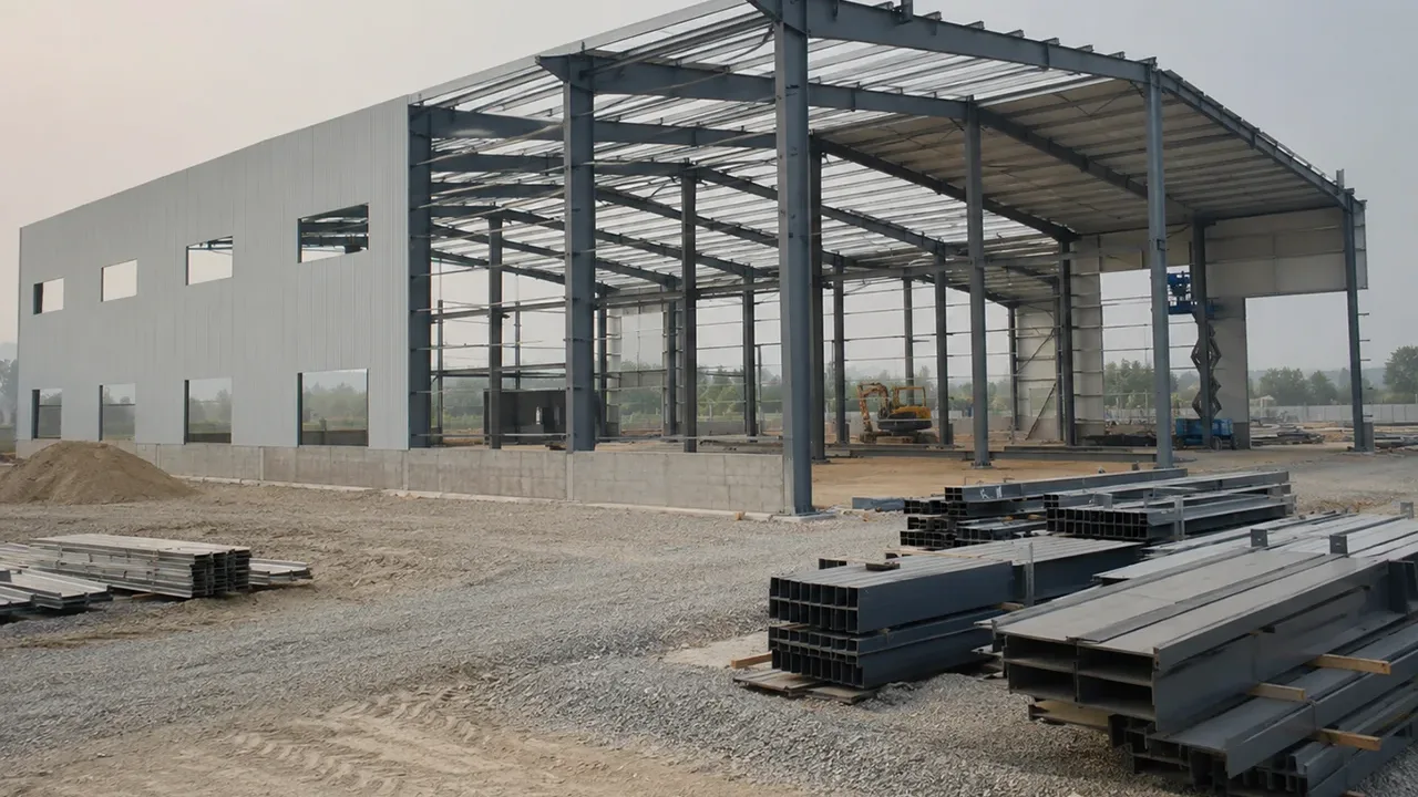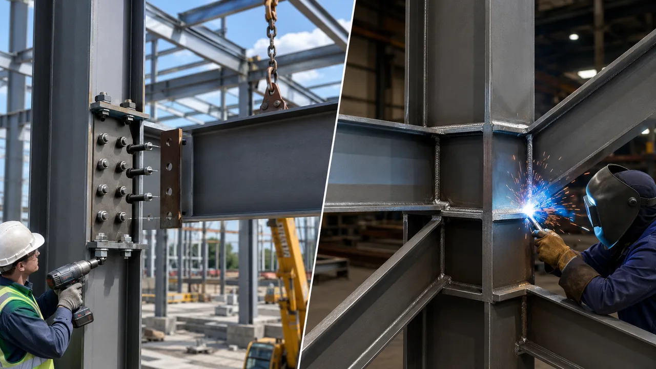
Choosing between a bolted end-plate vs welded connection affects much more than the appearance of a steel joint. The decision can influence structural stiffness, fabrication time, erection speed, inspection requirements, labor costs, weather sensitivity, and the ability to modify the structure in the future.
A bolted end-plate connection normally combines shop welding with site bolting. The end plate is welded to the beam under controlled factory conditions, and the completed beam is then connected to the supporting column or structural member using high-strength bolts. A welded connection may transfer forces directly through weld metal, either in the fabrication workshop or at the construction site.
Neither system is automatically better for every project. The most appropriate solution depends on the forces being transferred, the required connection stiffness, workshop capability, site access, erection schedule, inspection level, environmental exposure, and total installed cost.
What Are Bolted End-Plate and Welded Connections?
Bolted End-Plate Connection
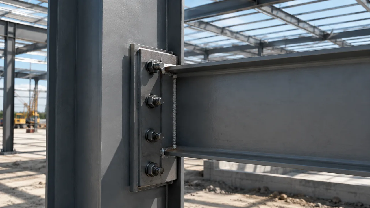
A bolted end-plate connection uses a steel plate welded to the end of a beam, rafter, or another structural member. The plate is then bolted to a column flange, another beam, or a supporting frame.
Its main components typically include:
- A steel end plate
- High-strength bolts, nuts, and washers
- Welds between the end plate and the beam flanges or web
- The supporting column flange or connecting member
- Stiffeners when additional strength or stiffness is required
The welding is normally completed in the fabrication workshop, where positioning, temperature, access, and quality control are easier to manage. At the project site, the connection is completed by aligning the bolt holes, installing the bolts, and tightening them to the specified condition.
Welded Connection
A welded connection joins steel components by melting and fusing the base material with weld metal. The weld creates a continuous or partially continuous load path between the connected elements.
Common weld types include:
- Fillet welds
- Complete joint penetration groove welds
- Partial joint penetration groove welds
- Plug, slot, and other specialized welds
Welding can be performed in a workshop or in the field. Shop welding usually offers better access, stable working conditions, controlled positioning, and more consistent inspection. Field welding may be necessary for certain large assemblies or continuous structural details, but it is more sensitive to weather, site access, working position, and welder qualification.
Bolted End-Plate vs Welded Connection: Key Differences
| Comparison Factor | Bolted End-Plate Connection | Welded Connection |
|---|---|---|
| Connection method | Shop-welded plate with site-installed bolts | Steel members joined directly through weld metal |
| Workshop fabrication | Requires plate cutting, drilling, fitting, and welding | Requires edge preparation, fitting, welding, and distortion control |
| Site installation | Usually fast once holes are aligned | May require holding, alignment, multiple weld passes, and cooling time |
| Skilled site labor | Qualified bolting crew and inspection | Qualified welders and often more extensive inspection |
| Weather sensitivity | Relatively low, although surfaces must remain suitable for bolting | Higher, especially for field welding in wind, rain, or low temperatures |
| Dimensional tolerance | Dependent on accurate hole alignment and erection tolerances | Dependent on fit-up, joint preparation, alignment, and welding sequence |
| Inspection | Bolt grade, installation, pretension, and surface condition | Weld size, profile, penetration, fusion, and internal defects |
| Dismantling potential | Possible in some applications | Normally requires cutting and may damage the components |
| Appearance | Bolts and plates are visible | Can provide a cleaner and more compact joint |
| Typical use | Prefabricated buildings, moment frames, industrial structures | Built-up members, trusses, plate girders, and complex assemblies |
Structural Behavior and Load Transfer
How Bolted End-Plate Connections Transfer Loads
In a beam-to-column end-plate joint, forces are transferred from the beam flanges and web into the end plate. The end plate then transfers those forces through the bolts into the column flange or supporting member.
Depending on the connection type, the bolts may resist:
- Tension caused by bending moment
- Shear from vertical or horizontal loading
- Bearing against the bolt holes
- Slip at the contact surface
- Combined tension and shear
The end plate itself may bend between the beam flange and the bolt rows. This deformation can create prying action, which increases the tension force in the bolts. End-plate thickness, bolt spacing, bolt diameter, edge distance, weld size, and column-flange stiffness must therefore be considered together.
A thin plate may appear economical but can increase plate deformation and bolt demand. A thicker plate may reduce prying forces but increase material cost and welding requirements.
How Welded Connections Transfer Loads
A welded connection transfers forces through the weld throat into the supporting steel. Its capacity depends on the weld type, effective length, penetration, orientation, base-metal strength, and the direction of loading.
Fillet welds are widely used for shear connections, stiffeners, brackets, secondary members, and built-up components. Groove welds may be used when a more direct transfer of axial force or bending moment is required.
The load path should remain as direct as possible. Unnecessary eccentricity can create additional bending or torsion. Poor fit-up, incomplete fusion, cracks, undercut, porosity, or insufficient penetration can reduce the actual capacity of the joint.
Rigid, Semi-Rigid, and Pinned Behavior
A connection is not automatically rigid because it is welded, nor automatically pinned because it is bolted. Its behavior depends on the geometry, stiffness, strength, and deformation of every component in the joint.
Bolted end-plate configurations may include:
- Simple shear end-plate connections
- Flush end-plate moment connections
- Extended end-plate moment connections
- Stiffened end-plate connections
Welded joints can also be designed to transfer shear, axial force, moment, or a combination of these actions. The structural analysis model must match the expected connection response.
Types of Bolted End-Plate Connections
Flush End-Plate Connection
A flush end plate remains within the overall depth of the beam. It can provide a compact joint and is commonly used for shear connections or moderate moment transfer.
Its capacity may be limited by the available space for bolt rows, end-plate bending, beam-flange forces, or column-flange deformation.
Extended End-Plate Connection
An extended end plate projects beyond one or both beam flanges. The additional plate area provides space for more bolt rows and a larger lever arm between the tension and compression zones.
This arrangement is often used for moment-resisting beam-to-column joints in industrial and multistory steel buildings.
Stiffened End-Plate Connection
Stiffeners can be added to the beam, end plate, column flange, or column web when local deformation or force concentration would otherwise control the design.
A proper bolted end-plate design must coordinate plate thickness, bolt arrangement, weld size, stiffeners, and the capacity of the supporting column.
Types of Welded Connections
Fillet-Welded Connection
Fillet welds are economical and easy to apply where two steel surfaces meet at an angle. They are commonly used for secondary connections, stiffeners, built-up sections, and web connections.
Their capacity depends on the effective throat, weld length, loading direction, and quality of execution.
Full-Penetration Welded Connection
A complete joint penetration weld is intended to develop force transfer through the full thickness of the connected element. It may be selected for critical moment joints, heavy axial-force connections, or details requiring high continuity.
This type of weld normally requires edge preparation, controlled root conditions, multiple weld passes, qualified procedures, and more extensive inspection.
Partial-Penetration Welded Connection
A partial joint penetration weld does not extend through the full thickness of the connected material. It can reduce welding time and heat input when full penetration is unnecessary.
Its strength must be calculated using the effective penetration rather than the total plate thickness.
Shop-Welded vs Field-Welded Connections
Shop welding is generally preferred because the fabricator can control access, positioning, consumables, temperature, and inspection. Members can often be rotated so that welding is performed in a favorable position.
Field welding may be appropriate where transportation limits prevent full factory assembly or where structural continuity is required at the site. However, it may increase crane standby time, temporary support requirements, safety controls, and inspection costs.
Fabrication Requirements
The fabrication stage has a major influence on whether a steel connection can be installed quickly and perform as intended. Accurate cutting, drilling, welding, fit-up, and dimensional inspection are essential because small workshop errors can become serious erection problems once the members arrive at the construction site.
Although bolted end-plate and welded connections use different final joining methods, both require controlled fabrication procedures. The fabricator must coordinate the approved structural drawings, connection details, material grades, welding procedures, bolt specifications, dimensional tolerances, coating requirements, and erection sequence before production begins.
Fabricating Bolted End-Plate Connections
The fabrication of a bolted end-plate connection normally begins with the preparation of the end plate and the beam end. The end plate must be cut to the approved width, height, and thickness, while the beam must be prepared so that the plate can be positioned squarely against its end.
The fabrication process normally includes:
- Verifying the steel grade and end-plate thickness
- Cutting the end plate to the approved dimensions
- Drilling or punching the bolt holes
- Checking bolt-hole diameter, spacing, gauge, and edge distance
- Preparing the beam flanges and web
- Positioning the end plate against the beam end
- Tack welding the plate before final dimensional checks
- Welding the plate to the beam flanges and web
- Checking plate squareness and alignment
- Inspecting weld size, continuity, and surface condition
- Completing a trial assembly when required
- Applying the specified surface preparation and protective coating
Bolt-hole accuracy is one of the most important fabrication requirements. The holes in the end plate must align with the corresponding holes in the column flange, supporting beam, or connection plate. A small error in a single joint may be manageable, but repeated dimensional errors across several frames can create significant erection delays.
Hole patterns should therefore be checked using approved templates, digital measuring equipment, CNC drilling systems, or trial-fit assemblies. The fabricator should verify the distance between bolt rows, the horizontal gauge, the edge distance, and the relationship between the bolt group and the beam centerline.
The end plate must also remain square to the beam. If the plate is tilted, twisted, or offset, the beam may not sit correctly against the supporting member. This can create gaps between the connected surfaces, uneven bolt loading, local plate bending, or difficulty installing the full bolt group.
Tack welding should be completed carefully because excessive or poorly positioned tack welds can pull the plate out of alignment. Before final welding begins, the fabricator should confirm:
- The overall beam length
- The position of the end plate
- The orientation of the bolt pattern
- The distance between the plate and nearby stiffeners
- The required weld access around the beam flanges and web
The welding sequence is also important. Welding one side of the plate continuously before welding the opposite side may introduce angular distortion. Balanced welding on opposing sides can help control movement and keep the plate perpendicular to the beam.
Where an extended or stiffened end-plate connection is used, additional components may include beam stiffeners, continuity plates, haunches, or reinforcement plates. These elements must be positioned accurately because they affect the connection stiffness, force path, and erection clearance.
A trial assembly may be required for large, heavily loaded, or repetitive connections. Trial fitting allows the fabricator to confirm that the bolt holes align, the plates bear correctly, and the members can be assembled without forcing, flame cutting, or uncontrolled hole enlargement at the construction site.
Surface treatment must also be coordinated with the connection design. If the joint is specified as slip-critical, the contact surfaces may require a particular surface condition or approved coating. Paint, oil, rust, or contamination on these surfaces can reduce the required slip resistance.
Protective coating should not fill the bolt holes or create excessive buildup around the plate edges. Areas that are difficult to access after assembly should be cleaned and coated before the connection is completed.
Fabricating Welded Connections
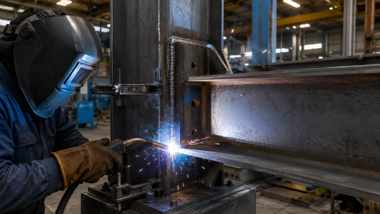
Welded connections require precise fit-up, suitable joint preparation, qualified welding procedures, and careful control of heat input. The quality of the completed joint depends not only on the visible weld size but also on penetration, fusion, root condition, weld sequence, and the properties of the surrounding base metal.
Welded joints may require:
- Verification of the steel grade and material thickness
- Edge beveling or groove preparation
- Cleaning of the weld area
- Fit-up and alignment of the connected members
- Control of root gaps and groove angles
- Installation of backing bars where required
- Tack welding
- A controlled welding sequence
- Preheating or interpass-temperature control
- Cleaning between weld passes
- Distortion monitoring and correction
- Visual or nondestructive inspection
- Repair of unacceptable weld defects
Joint preparation must follow the approved welding detail. Groove angle, root opening, root face, backing material, and alignment directly influence whether the welder can achieve the required penetration and fusion.
Before welding begins, the surfaces should be cleaned of moisture, oil, paint, heavy rust, scale, and other contaminants that could cause porosity, cracking, or incomplete fusion. The fit-up should also be checked to confirm that gaps and misalignment remain within the permitted tolerances.
Large gaps should not automatically be filled by depositing excessive weld metal. This can increase heat input, shrinkage, distortion, residual stress, and welding time. If the joint does not fit correctly, the fabricator should follow an approved repair or adjustment procedure rather than improvising on the production floor.
Tack welds must be strong enough to hold the components in position during final welding. They should be placed where they will not interfere with the finished weld or create defects. Where tack welds become part of the final joint, they should meet the same quality requirements as the permanent weld.
The welding sequence should be planned to distribute heat as evenly as possible. Long, continuous welds applied on only one side of a member may cause bowing, twisting, or angular distortion. The fabricator may use balanced welding, back-step sequences, intermittent welding, temporary restraints, or presetting to control movement.
Preheating may be required for thick steel, high-strength material, restrained joints, low ambient temperatures, or situations with an increased risk of hydrogen cracking. The required preheat temperature should be maintained over the specified area before welding begins. For multi-pass welds, the interpass temperature should also be controlled. Excessively low temperatures can increase cracking risk, while excessive heat can affect material properties, enlarge the heat-affected zone, and increase distortion.
Each weld pass should be cleaned before the next pass is applied. Slag, spatter, and surface defects must be removed so that subsequent weld metal can fuse properly with the previous layer.
After welding, the completed joint should be inspected for:
- Correct weld size and effective length
- Acceptable weld profile
- Cracks
- Undercut
- Porosity
- Overlap
- Incomplete fusion
- Incomplete penetration
- Arc strikes outside the weld area
- Excessive distortion or misalignment
Critical welded connections may require nondestructive testing. Ultrasonic testing may be used for complete joint penetration welds, while magnetic-particle or dye-penetrant testing may be used to identify surface-breaking defects.
If an unacceptable defect is found, the repair procedure should identify how the defective weld metal will be removed, how the area will be cleaned and prepared, and how the repair weld will be inspected. Repeated repair welding should be controlled because additional heat cycles can increase distortion and affect the surrounding steel.
Excessive heat input can distort the member or create significant residual stress. Balanced welding sequences, temporary restraints, controlled procedures, dimensional checks, and qualified welders help limit these effects and improve the consistency of the finished connection.
Dimensional Tolerances
Bolted systems allow limited adjustment through approved hole tolerances, erection clearances, and shimming where permitted. However, misaligned holes should not be forced into position by uncontrolled cutting or enlargement.
Welded connections require accurate fit-up before welding begins. Large gaps or misalignment can change the weld geometry, increase weld volume, and reduce joint quality.
Site Installation and Construction Speed
Bolted End-Plate Installation
At the site, the beam is lifted into position, the holes are aligned, temporary bolts may be installed, and the complete bolt group is tightened according to the specified procedure.
This process is well suited to repeated frames and prefabricated steel construction. It also reduces the amount of hot work, welding equipment, consumables, and weld inspection required at height.
Welded Connection Installation
A field-welded joint must remain supported and aligned until the required weld has been completed and has developed sufficient strength. The operation may involve edge cleaning, preheating, multiple passes, slag removal, cooling, and inspection.
Restricted access, overhead welding positions, rain, wind, and low temperatures can reduce productivity and make quality control more difficult.
Temporary Stability During Erection
Neither bolted nor welded joints should be assumed to provide complete building stability immediately after initial placement.
Bolted joints may help stabilize members quickly, but temporary bracing is still necessary until the permanent frames, roof bracing, wall bracing, and secondary members are installed. Welded joints may require temporary supports for a longer period while welding and inspection are completed.
Quality Control and Inspection
Bolted Connection Inspection
Inspection may include:
- Bolt grade and diameter
- Bolt length and thread position
- Washer installation
- Hole condition and alignment
- Snug-tight or pretensioned installation
- Approved tightening method
- Contact-surface condition
- Preparation of slip-critical surfaces where required
Adequate wrench clearance must be provided around every bolt. A structurally adequate joint can still be difficult to install if the bolt head or nut cannot be reached.
Weld Inspection
Weld inspection may assess:
- Weld size and effective length
- Profile and surface condition
- Cracks
- Porosity
- Undercut
- Incomplete fusion
- Incomplete penetration
- Arc strikes and other surface damage
Critical joints may require ultrasonic, magnetic-particle, dye-penetrant, or radiographic testing, depending on the weld type and project requirements.
Cost Comparison
A realistic comparison between a bolted end-plate vs welded connection must consider the total installed cost rather than only the amount of steel or the number of bolts.
Bolted end-plate connections require plates, high-strength bolts, drilling, shop welding, and dimensional control. However, they can shorten site installation and reduce field-welding labor.
Welded connections may eliminate end plates and bolts, but they can require more edge preparation, welding consumables, skilled labor, temporary support, inspection, and distortion control.
The final cost is influenced by:
- Number of repeated joints
- Local labor rates
- Workshop automation
- Site accessibility
- Crane standby time
- Weather conditions
- Required inspection level
- Connection complexity
- Construction schedule
A connection with a higher material cost may still produce a lower total project cost if it can be fabricated repeatedly and installed quickly.
Performance Under Different Project Conditions
High Seismic Demand
Seismic performance depends on connection strength, stiffness, deformation capacity, ductility, panel-zone behavior, bolt response, weld quality, and the surrounding frame.
Neither connection type should be described as universally superior in seismic applications. The complete joint must be detailed and qualified for the required structural system and expected inelastic behavior.
Fatigue and Repeated Loading
Fatigue can be important in crane buildings, bridges, industrial platforms, machinery supports, and structures exposed to repeated vibration.
Weld toes, abrupt geometry changes, attachments, and weld defects may create stress concentrations. Bolted joints must also be checked for slip, bearing, bolt-force fluctuation, plate deformation, and fatigue in the connected material.
Corrosive Environments
Moisture can collect between end plates or around poorly sealed interfaces. Bolted joints should provide adequate drainage, coating access, and compatible surface treatment.
Welded details can remove some crevices but may create areas that are difficult to coat or inspect. Galvanizing, sealing, drainage, and coating-repair procedures should be coordinated during design.
Fire Protection
Both systems may require fireproofing. End plates, bolts, stiffeners, welds, and supporting members should remain accessible for installation and inspection before the fire-protection material is applied.
Advantages and Limitations
Advantages of Bolted End-Plate Connections
- Fast site installation
- Reduced field welding
- Suitable for repeated and standardized frames
- Compatible with prefabricated and modular construction
- Most welding is completed under workshop conditions
- Potential for dismantling or future modification
- Visual access to installed bolts
Limitations of Bolted End-Plate Connections
- Accurate hole coordination is required
- End-plate bending can increase bolt forces
- Prying action must be considered
- Wrench clearance is required
- Column flanges or webs may require stiffeners
- Plates and bolts remain visible
Advantages of Welded Connections
- Compact and visually clean details
- No bolt holes are required
- Direct load transfer can be achieved
- Suitable for irregular geometry
- Effective for shop-fabricated assemblies
- High capacity is possible with appropriate detailing
Limitations of Welded Connections
- Quality depends heavily on welding procedures and workmanship
- Field welding is sensitive to weather and access
- Heat can cause distortion and residual stress
- Inspection may be more complex
- Defect repair can delay construction
- Dismantling usually damages the components
Typical Applications
Bolted end-plate connections are commonly used in:
- Industrial steel buildings
- Factories and workshops
- Warehouses
- Multistory steel buildings
- Prefabricated structures
- Modular steel systems
- Moment-resisting frames
- Beam-to-column joints
Welded connections are commonly used in:
- Built-up steel members
- Steel trusses
- Plate girders
- Architectural steelwork
- Shop-fabricated frames
- Heavy industrial components
- Joints with restricted bolt access
- Continuous structural assemblies
Common Design and Construction Mistakes
| Common Mistake | Possible Consequence | Better Approach |
|---|---|---|
| End plate is too thin | Excessive plate bending and higher bolt tension | Check plate deformation and prying action |
| Bolt spacing is inadequate | Bearing failure, tearing, or installation difficulty | Coordinate structural limits and tool access |
| Column flange is not checked | Local bending or failure of the supporting member | Evaluate the complete column flange and web system |
| Weld size is selected without calculation | Insufficient strength or unnecessary weld volume | Design the weld for the actual force path |
| Field welding proceeds in poor weather | Reduced weld quality and construction delays | Use approved weather protection and welding controls |
| Wrench or welding access is ignored | The connection cannot be completed or inspected properly | Review installation access during detailing |
| New suspended loads are added after fabrication | Overloading of beams, plates, bolts, or welds | Coordinate service loads before structural detailing |
| Temporary supports are removed too early | Member movement, instability, or connection damage | Follow an engineered erection sequence |
How to Choose Between a Bolted End-Plate and Welded Connection
A practical selection process should include the following steps:
- Identify the shear, axial force, moment, and torsion to be transferred.
- Determine whether the joint should behave as pinned, semi-rigid, or rigid.
- Review the fabricator’s drilling, welding, and assembly capabilities.
- Evaluate site access, weather, working height, and available equipment.
- Compare field bolting with field-welding requirements.
- Review the erection sequence and project schedule.
- Confirm inspection and testing requirements.
- Evaluate seismic, fatigue, fire, and corrosion conditions.
- Consider future modification, extension, or dismantling.
- Compare the total installed and lifecycle costs.
Which Connection Is Better?
There is no universal answer to the bolted end-plate vs welded connection comparison.
A bolted end-plate connection is often preferred when erection speed, repeated detailing, modular construction, and reduced field welding are important. It is especially effective when the fabrication workshop can accurately produce standardized members and bolt-hole patterns.
A welded connection may be more suitable when a compact joint is required, the geometry is irregular, bolt access is limited, or the assembly can be welded under controlled workshop conditions.
Many efficient steel structures use a combination of both methods. A common example is an end plate welded to the beam in the workshop and bolted to the column at the project site. This arrangement uses controlled shop welding while preserving fast and practical site erection.
Final Considerations
The choice between bolted and welded steel joints should be based on structural performance, fabrication capability, erection conditions, inspection access, environmental exposure, construction time, and total cost.
The structural engineer, steel detailer, fabricator, erector, coating contractor, and inspector should coordinate the joint before manufacturing begins. A connection that is strong on paper may still cause problems if it cannot be fabricated accurately, transported safely, installed efficiently, coated properly, or inspected completely.
The right steel joint is therefore not simply the connection with the fewest bolts or the smallest amount of weld metal. It is the connection that safely transfers the required forces while remaining practical to manufacture, install, inspect, maintain, and adapt throughout the service life of the structure.