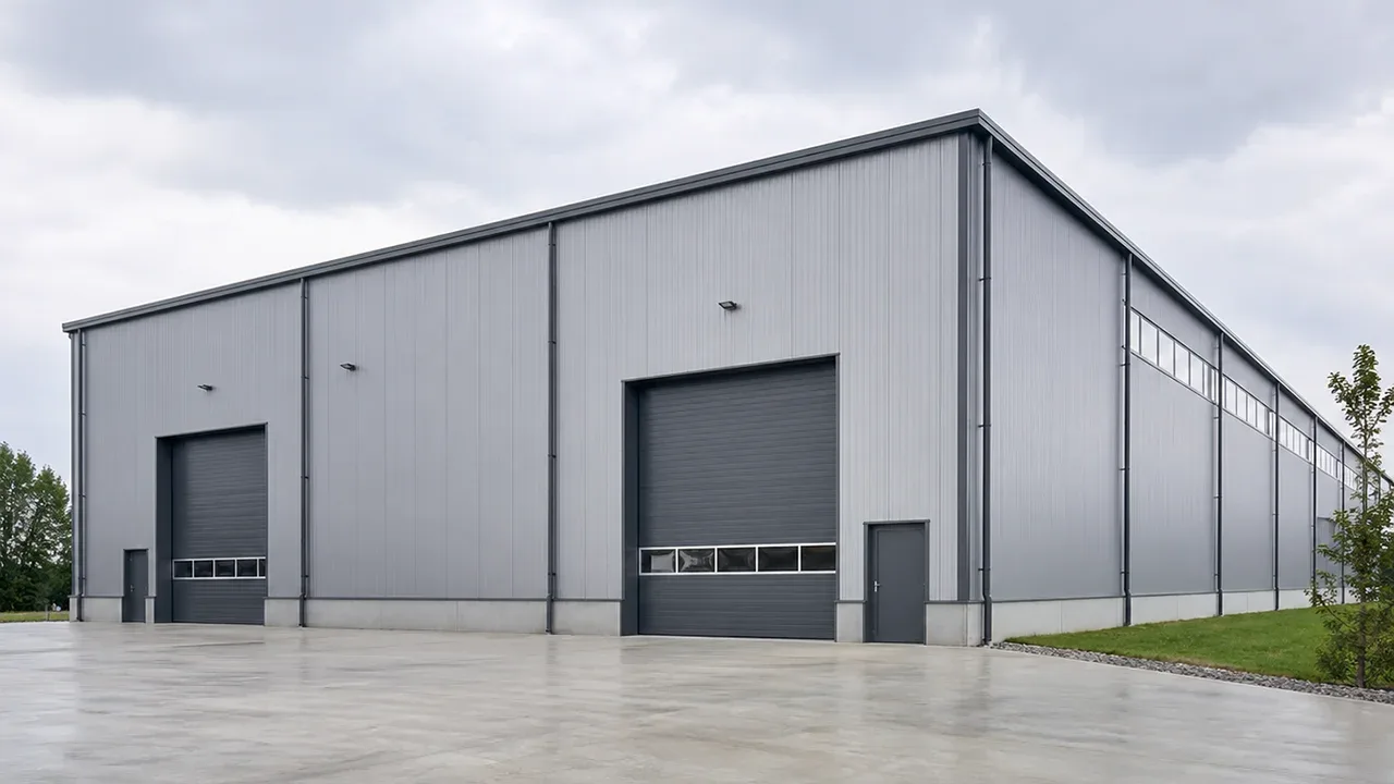
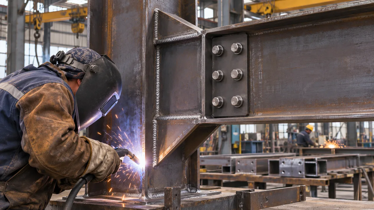
Steel connections transfer forces between beams, columns, braces, plates, and other structural members. Their performance depends not only on the strength of individual fasteners or welds but also on how loads move through the complete connection. A connection with large bolts or heavy welds can still be inadequate if the plate, base metal, bolt arrangement, or local load path becomes the governing limit state.
For this reason, weld and bolt capacity should be evaluated as part of an integrated connection system. Designers must consider shear, tension, bending moment, eccentricity, plate strength, connection stiffness, fabrication tolerances, and the interaction between individual components before determining whether a detail can safely transfer the required forces.
Why Weld and Bolt Capacity Matters in Steel Connections
Structural members are only as effective as the connections that allow forces to pass between them. A beam may have sufficient flexural strength and a column may satisfy axial-load requirements, but the structural load path can still be interrupted if the connection between them is insufficient.
Connection design therefore involves more than choosing a bolt diameter or specifying a weld size. The required force must pass through the connected member, into a plate or fitting, through bolts or welds, and finally into the supporting member. Each part of this sequence can introduce a different limit state.
This coordination is particularly important in warehouses, factories, industrial buildings, platforms, pipe racks, and other steel structures where connections may experience substantial shear, axial force, moment, or combinations of these actions.
How Loads Are Transferred Through Welded and Bolted Connections
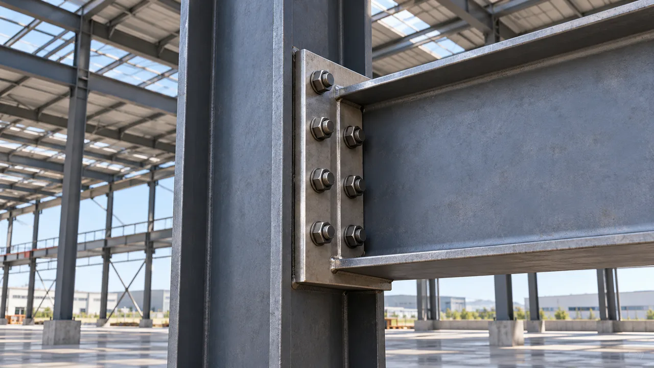
A steel connection may be required to transfer several types of force simultaneously. These commonly include:
- Axial tension or compression
- Vertical or horizontal shear
- Bending moment
- Torsion caused by eccentric loading
- Combined shear and tension
The actual connection force does not disappear at the bolt or weld. Instead, the force moves through a complete load path. For example, a beam reaction may pass from the beam web into a shear plate through welds, from the shear plate into bolts, and then from the bolts into the supporting column through bearing and local plate stresses.
Understanding this load path is essential when evaluating weld and bolt capacity because the strongest component does not necessarily determine the strength of the entire connection.
Understanding Weld Capacity in Steel Connection Design
Weld capacity depends on weld type, effective weld area, filler-metal strength, loading direction, connection geometry, and the strength of the connected base material. Fillet welds are widely used in structural fabrication, while groove welds are often selected where more direct or higher-capacity force transfer is required.
Fillet Weld Capacity
The strength of a fillet weld is influenced by its effective throat rather than simply its visible leg dimension. Weld length, weld size, electrode classification, loading direction, and the configuration of the weld group all affect the available resistance.
Increasing weld size can increase capacity, but an excessively large weld is not automatically an efficient solution. Larger welds require more deposited weld metal, more fabrication time, and greater heat input. The connected plate or base material must also be capable of developing the force transferred through the weld.
Groove Weld Capacity
Groove welds may be designed as complete-joint-penetration or partial-joint-penetration welds depending on the structural requirement and joint configuration. Their performance depends on joint preparation, effective weld dimensions, filler metal, base metal, and applicable welding procedures.
When a connection demands significant force transfer, the designer should confirm whether weld metal strength, base-metal yielding or rupture, or another local limit state controls the detail.
Effective Weld Length and Weld Group Behavior
A weld group subjected to a concentric shear force may have a relatively straightforward force distribution. When the load acts away from the weld-group centroid, however, eccentricity creates an additional moment. Different portions of the weld group can then experience different force demands.
This means the connection should not always be evaluated by dividing the total force uniformly over the total weld length. Geometry and eccentricity may make the most highly stressed region of the weld group critical.
For additional structural welding guidance and design considerations, refer to the AISC resource on Welding capacity.
Understanding Bolt Capacity in Steel Connection Design
Bolted connections must be checked for the forces acting on the bolts as well as the behavior of the surrounding plates. Bolt grade, diameter, number of bolts, hole type, loading direction, and connection geometry all influence the available resistance.
Bolt Shear Capacity
Bolts transferring transverse loads may be subjected primarily to shear. The available shear resistance depends on bolt material strength, diameter, number of effective shear planes, and whether threads are located within the shear plane where relevant to the applicable design method.
Connection geometry also matters. A group of bolts loaded concentrically can behave differently from a bolt group carrying an eccentric force that produces both direct shear and rotational effects.
Bolt Tension Capacity
Bolts may also transfer tensile forces, particularly in moment connections, end-plate connections, brackets, and other details where the connected components tend to separate.
Bolt tension cannot always be considered independently from deformation of the connected plate. Flexible plates can introduce additional bolt forces through prying action, increasing bolt demand beyond the force predicted by a simplified direct-tension model.
Combined Shear and Tension
Some bolts resist shear and tension at the same time. In these situations, checking the bolt independently for full shear capacity and full tension capacity can overlook the interaction between the two force components.
The connection design should therefore consider the applicable combined-force interaction requirements rather than assuming the two capacities are completely independent.
Bearing and Tear-Out Around Bolts
A bolt itself may have adequate strength while the plate around the bolt hole does not. Local bearing stress develops where the bolt bears against the side of the hole, and high forces can cause local deformation or failure of the connected material.
Important variables include:
- Plate thickness
- Steel strength
- Bolt diameter
- Hole dimensions
- Edge distance
- Bolt spacing
- Direction of loading
If a bolt is positioned too close to a plate edge, the material between the hole and the edge may tear out before the bolt reaches its own strength. Increasing bolt diameter alone therefore does not guarantee a proportional increase in connection capacity.
Slip-Critical vs Bearing-Type Bolted Connections
Bolted joints may be designed to transfer forces through bearing behavior or, where required, through friction between properly prepared faying surfaces. The required connection behavior depends on structural function, loading conditions, service requirements, and the applicable design specification.
In a bearing-type connection, some movement may occur until the bolt shank bears against the hole. In a slip-critical joint, bolt pretension and surface condition are used to resist slip at the interface under the specified loading condition.
Designers should distinguish between resistance to slip and the ultimate strength limit states of the bolts and connected plates.
Weld Capacity vs Bolt Capacity
| Design Factor | Welded Connection | Bolted Connection |
|---|---|---|
| Main Strength Mechanism | Weld metal and connected base metal | Bolt shear or tension and connected plate behavior |
| Key Variables | Weld size, effective length, electrode strength, geometry | Bolt grade, diameter, number, spacing, and hole geometry |
| Fabrication | Commonly performed in the shop or field | Commonly assembled in the shop or during erection |
| Inspection | Weld quality, dimensions, continuity, and defects | Bolt condition, installation, pretension, and hole alignment |
| Typical Local Limit States | Weld rupture and base-metal failure | Bolt shear, bolt tension, bearing, and tear-out |
| Adjustment During Erection | Generally less flexible after welding | Usually easier to assemble and adjust |
Neither connection type is universally stronger. The appropriate solution depends on loading, geometry, fabrication method, erection sequence, inspection requirements, and the overall structural system.
What Determines Weld and Bolt Capacity
Material Strength
The strength of structural steel, bolts, electrodes, and connecting plates establishes the basic resistance available within the connection. Selecting stronger fasteners may increase one component’s resistance, but the surrounding material must also be capable of transferring the resulting force.
Connection Geometry
Plate thickness, bolt spacing, edge distance, weld location, bolt-row position, and connection dimensions affect force distribution. Eccentric geometry can introduce secondary moments and produce significantly different forces across a weld or bolt group.
Load Direction
Connections behave differently under shear, tension, compression, moment, and combinations of these actions. The orientation of the applied force relative to a weld line or bolt group can therefore influence the governing capacity.
Fabrication Quality
Actual connection performance also depends on execution. Weld discontinuities, inaccurate bolt holes, poor fit-up, incorrect bolt installation, or dimensional deviations can reduce the reliability of a detail that appears adequate on design drawings.
How Weld Groups Resist Eccentric Loads
When a load acts through the centroid of a weld group, the force distribution can often be evaluated primarily as direct loading. When the force is offset, the eccentricity generates a moment in addition to the direct force.
The resulting demand is therefore not uniform around the weld group. Portions farther from or unfavorably positioned relative to the group centroid may experience higher stresses. This is particularly relevant for brackets, equipment supports, cantilever connections, and other details with offset loading.
How Bolt Groups Resist Eccentric Loads
Bolt groups follow a similar principle. Direct shear may be distributed among the bolts, while eccentric loading creates an additional rotational effect. Bolts located farther from the bolt-group centroid can attract larger forces from the moment component.
For this reason, using only the total load divided by the number of bolts may be unconservative for an eccentrically loaded connection. The force in the most highly loaded bolt must be evaluated according to the connection model and design method being used.
Connection Plate Capacity Must Be Checked Too
The plate connecting the bolts or welds may govern before either fastener system reaches its nominal strength. Typical plate limit states include:
- Gross-section yielding
- Net-section rupture
- Block shear
- Bearing at bolt holes
- Edge tear-out
- Local plate bending
This is one of the most important principles in weld and bolt capacity design. Increasing the size of a weld or installing stronger bolts may simply shift the critical failure mode into the plate or supporting member.
Weld and Bolt Capacity in Moment Connections
Moment connections often require several connection components to work together. Beam flange forces may create high tension and compression demands, while the web transfers a significant portion of the shear force.
End plates, flange plates, welded flanges, bolted end plates, stiffeners, and supporting column elements may all participate in the load path. Bolt tension, plate bending, weld strength, local flange behavior, and panel-zone or web behavior can therefore become interconnected design considerations.
A well-proportioned moment connection should provide a clear load path without creating a single unnecessarily weak or excessively stiff local component.
Weld and Bolt Capacity in Shear Connections
Simple shear connections frequently combine welded and bolted components. A shear tab, for example, may be welded to a supporting column and bolted to a beam web. In this arrangement, the weld and bolt group transfer the same overall reaction through different stages of the load path.
The weld must be capable of transferring force from the plate into the support, while the bolts and beam web must transfer the reaction between the beam and plate. Plate shear, bearing, block shear, and weld strength should therefore be coordinated rather than checked as unrelated components.
Coordinating Welded and Bolted Components in the Same Connection
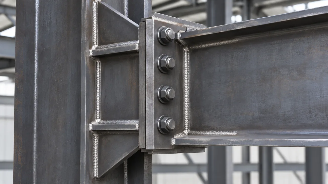
Many practical structural details contain both welding and bolting. Shop welding may be used to attach plates to columns, beams, or braces, while field bolts are used to complete the connection during erection.
The capacity of these elements should be balanced so that one part of the connection does not become disproportionately weak. Designers must also consider how the force actually moves through the plate, weld, bolts, and supporting member.
For a broader explanation of load paths, connecting plates, bolts, welds, and common detailing arrangements, see our steel structure connection details.
Common Design Mistakes When Checking Weld and Bolt Capacity
Connection calculations can appear straightforward while still overlooking an important local limit state. Common problems include:
- Checking bolt shear without checking bolt tension where both forces occur
- Ignoring plate bearing or tear-out around bolt holes
- Increasing weld size without checking the connected base metal
- Assuming equal bolt forces under eccentric loading
- Ignoring local plate bending and prying effects
- Using a nominal weld dimension without considering the effective throat
- Failing to account for fabrication and erection tolerances
- Designing individual components without tracing the complete load path
A connection is most reliable when every important limit state is reviewed as part of the same structural force-transfer mechanism.
Fabrication and Inspection Considerations
Connection capacity calculated during design must ultimately be achieved in fabrication and erection. Weld accessibility, welding position, joint preparation, fit-up, dimensional control, bolt-hole alignment, bolt installation, and inspection requirements can all influence the practicality of a connection.
Shop welding is often selected where controlled fabrication conditions are advantageous, while bolted field connections can simplify erection and reduce on-site welding. However, the final arrangement should be selected according to structural requirements rather than fabrication convenience alone.
How XTD Steel Structure Coordinates Connection Capacity
XTD Steel Structure coordinates connection detailing with member forces, fabrication requirements, transportation constraints, and erection conditions. Connection loads are reviewed together with plate geometry, weld configuration, bolt arrangement, stiffeners, and the surrounding structural members.
This approach helps prevent a situation where an individual weld or bolt satisfies its isolated calculation while another component interrupts the intended load path. Fabrication drawings and connection details should clearly communicate dimensions, bolt layouts, weld requirements, plate thicknesses, and other information required for production and erection.
Practical Design Takeaway for Weld and Bolt Capacity
Weld and bolt capacity should never be treated as an isolated comparison between two connection methods. Both are components within a larger structural load path.
A larger weld cannot compensate for an inadequate plate, and a stronger bolt cannot prevent tear-out caused by insufficient edge distance. Effective connection design requires coordinated checks of fasteners, welds, plates, base metal, geometry, stiffness, and load distribution.
When these elements are evaluated together, the final connection can provide the required strength while remaining practical to fabricate, inspect, transport, and erect.
FAQ About Weld and Bolt Capacity
What Is Weld and Bolt Capacity in Steel Connection Design?
It refers to the available resistance of welded and bolted components used to transfer structural forces between connected steel members. Their capacity must be evaluated together with plate and base-metal limit states.
How Is Weld Capacity Calculated in a Steel Connection?
Weld capacity depends on factors including weld type, effective throat or area, effective length, weld-metal strength, loading direction, weld-group geometry, and the strength of the connected base material.
What Determines the Shear Capacity of a Bolt?
Bolt shear capacity is influenced by bolt grade, bolt diameter, number of effective shear planes, thread location where applicable, and the design provisions used for the connection.
Can Bolts Resist Both Shear and Tension?
Yes. Bolts can be subjected to combined shear and tension, but the interaction between the two force components must be considered where required rather than checking each force independently at full capacity.
Is a Welded Connection Stronger Than a Bolted Connection?
Not necessarily. Either connection type can be designed for substantial structural forces. The governing strength depends on the complete connection geometry, materials, loading, fabrication, and applicable limit states.
Why Can a Connection Fail Even If the Bolts Are Strong Enough?
The surrounding plate may fail by bearing, tear-out, net-section rupture, block shear, or bending before the bolts reach their own resistance. Other connection components can also govern.
How Does Bolt Spacing Affect Connection Capacity?
Bolt spacing influences load transfer through the connected plate, the available material between adjacent holes, installation access, and several local plate limit states. Proper spacing is therefore an important part of bolted connection detailing.
Why Must Plate Capacity Be Checked Together With Weld and Bolt Capacity?
Welds and bolts transfer forces through connecting plates and supporting members. If those elements cannot develop the transferred force, increasing weld or bolt strength alone will not increase the capacity of the complete connection.