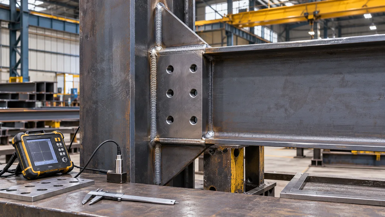
Steel connection design is often simplified into a comparison between bolt strength and weld strength. In practice, the reliability of a connection depends on much more than the nominal resistance of an individual fastener. Plates, base metal, bolt groups, weld groups, eccentricity, fabrication tolerances, installation quality, and the complete load path can all determine the actual connection capacity. Many weld and bolt capacity mistakes occur because one of these factors is overlooked while attention remains focused only on the bolt or weld itself.
These mistakes can create problems during design review, fabrication, erection, or service. A connection that appears adequate on paper may require field modification because bolts cannot be installed, welds cannot be accessed, or the connected plate is weaker than the fastener. Avoiding these problems requires the connection to be evaluated as a complete structural system rather than as a collection of isolated components.
Why Weld and Bolt Capacity Mistakes Occur
Treating Fastener Capacity as Connection Capacity
The resistance of a bolt or weld is only one part of the total connection. A strong bolt does not prevent plate bearing, tear-out, net-section fracture, or block shear. Likewise, a large weld does not prevent yielding or rupture of the surrounding base metal.
The governing limit state is often located outside the fastener itself. Engineers therefore need to compare the resistance of every component participating in the load-transfer path.
Simplifying the Load Path Too Much
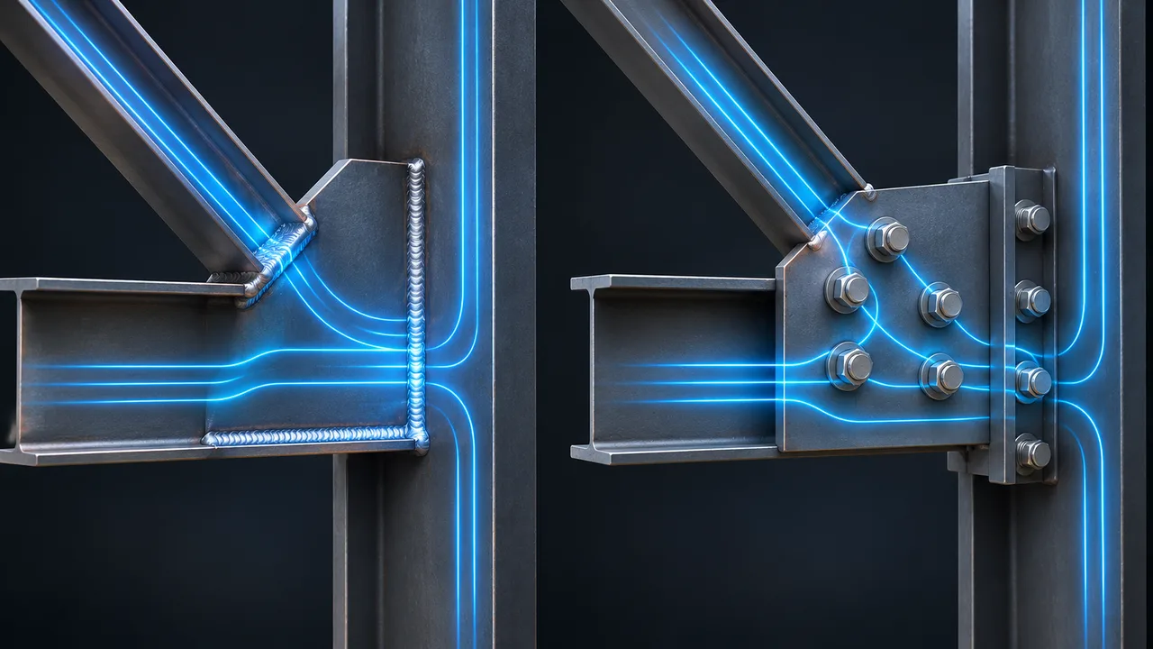
Structural forces must pass from one member through the connection and into another member. The path may include flanges, webs, gusset plates, end plates, stiffeners, bolts, welds, and supporting elements.
If any component along this path has insufficient resistance or stiffness, it can control the connection regardless of the nominal strength of the bolts or welds.
Separating Design from Fabrication and Erection
A connection may satisfy calculation requirements while still being difficult to manufacture or install. Restricted welding access, insufficient wrench clearance, inaccurate hole positioning, or unrealistic erection tolerances can reduce the practical reliability of the design.
Connection design should therefore consider fabrication and erection conditions from the beginning.
Mistake 1: Checking Only Individual Bolt Strength
Ignoring Bolt Group Behavior
Bolts rarely work as completely independent fasteners. In a bolt group, force distribution depends on bolt spacing, connection geometry, stiffness, deformation, and the location of the applied load.
When the load acts eccentrically, some bolts may carry significantly more force than others. Simply dividing the total load equally among all bolts may therefore underestimate the maximum bolt demand.
Ignoring Connected Plate Limit States
Even when the bolts have adequate shear or tension resistance, the connected plate must still be checked for bearing, tear-out, net-section fracture, and block shear.
These plate-related limit states frequently govern practical steel connections, particularly where thin plates, small edge distances, or closely spaced bolt holes are used.
Assuming a Stronger Bolt Always Creates a Stronger Connection
Increasing bolt grade does not automatically increase the capacity of the complete connection. If the plate is already controlling the design, stronger bolts may provide little or no additional usable resistance.
The connection must be balanced so the fasteners, plates, and surrounding structural members can transfer the required force together.
Mistake 2: Checking Weld Strength Without Checking the Base Metal
Oversizing Welds
One of the common weld and bolt capacity mistakes is increasing weld size without checking whether the connected steel can develop the additional resistance. A larger weld may simply shift the governing failure mode into the base metal.
Oversized welds can also increase heat input, fabrication time, material consumption, and distortion.
Ignoring Local Yielding and Rupture
The base metal adjacent to a weld must receive and distribute the force introduced through the weld. Local yielding, rupture, deformation, or other member limit states may become critical before the weld itself reaches its nominal resistance.
For this reason, weld design should always be coordinated with the strength and geometry of the connected material.
Using Weld Size as the Main Design Variable
Weld capacity depends on more than weld size. Effective throat, weld length, orientation, filler metal strength, load direction, and weld-group geometry all affect the available resistance.
Changing the arrangement of the weld may sometimes improve connection performance more effectively than simply increasing weld size.
Mistake 3: Ignoring Load Direction
Axial Loads
Connections subjected to axial loads behave differently depending on whether the force acts in tension or compression. Tension may control bolt tension, net-section fracture, weld rupture, or block shear, while compression may be transferred partly through direct bearing between connected surfaces.
The connection should be detailed according to the actual force-transfer mechanism rather than assuming the same behavior for every loading direction.
Shear Loads
Under shear, bolts may transfer force through shear resistance and plate bearing, while welded connections transfer force through the effective weld throat. Edge distance, plate thickness, weld orientation, and bolt-hole geometry can all influence the governing resistance.
Moment Loads
Moment creates a nonuniform distribution of force. Some bolts may experience high tension, while some weld segments may carry much greater stress than others.
Connections resisting moment should therefore be evaluated as bolt groups or weld groups rather than by checking only individual fasteners.
Mistake 4: Ignoring Combined Loading
Combined Tension and Shear in Bolts
A bolt may be acceptable under pure shear and also acceptable under pure tension, yet become inadequate when both actions occur simultaneously. Combined loading changes the amount of resistance available for each component of force.
The interaction between tension and shear must therefore be included where required by the connection behavior.
Combined Stress in Weld Groups
Weld groups may simultaneously resist direct shear, axial force, torsion, and bending moment. These actions create multiple stress components throughout the weld group.
The critical resultant stress must be determined instead of evaluating every load component completely independently.
Why Separate Checks Can Be Misleading
Separate calculations can make a connection appear adequate even when the combined demand is excessive. This is especially important in rigid frames, bracing connections, equipment supports, crane structures, and other systems where several actions occur together.
Mistake 5: Ignoring Connection Eccentricity
How Eccentricity Creates Additional Moment
Eccentricity occurs when the applied force does not pass through the effective center of resistance of the connection. The offset produces an additional moment equal to the applied force multiplied by the eccentric distance.
Even a moderate direct force can therefore create substantial additional demand.
Eccentric Bolt Groups
In an eccentric bolt group, bolts positioned farther from the center of rotation may carry larger forces than bolts closer to the center.
Ignoring this effect can underestimate the demand on the most highly loaded fastener.
Eccentric Weld Groups
Weld groups subjected to eccentric loading develop nonuniform stress. Certain weld segments may carry significantly higher demand because they resist both direct force and the secondary moment.
Mistake 6: Assuming Equal Load Distribution
Unequal Bolt Forces
Equal load sharing is sometimes a useful starting assumption for simple connections, but it is not valid for every configuration. Connection stiffness, bolt layout, plate deformation, and eccentric loading can produce substantial differences between individual bolt forces.
Unequal Weld Stresses
The same issue occurs in weld groups. Welds farther from the centroid or positioned unfavorably relative to the load direction may experience higher stress.
Why Average Demand Can Be Misleading
The average force in a bolt group or weld group may appear acceptable while the most highly stressed component exceeds its allowable resistance. Connection design must identify the critical location rather than relying only on average demand.
Mistake 7: Ignoring Prying Action in Bolted Connections
How Flexible Plates Increase Bolt Tension
Flexible end plates and flanges can deform under tensile loading. This deformation can create prying forces that increase bolt tension beyond the direct tensile force produced by the external load.
Why Direct Bolt Tension Is Not Always Enough
Checking only the externally calculated bolt tension may underestimate actual bolt demand. Prying action becomes particularly important where high-strength bolts are combined with relatively flexible plates.
Connection Geometry That Increases Prying Risk
Thin plates, large lever arms, flexible flanges, and certain end-plate arrangements can increase the potential for prying action. Increasing plate stiffness or modifying connection geometry may sometimes be more effective than simply selecting a stronger bolt.
Mistake 8: Poor Bolt Edge Distance and Spacing
Insufficient Edge Distance
Bolts positioned too close to the edge of a plate can cause tear-out before the bolt itself reaches its full resistance.
Adequate edge distance is therefore essential for developing reliable plate capacity.
Inadequate Bolt Spacing
Closely spaced bolt holes reduce the available steel between fasteners and can affect net-section strength, block shear resistance, fabrication tolerance, and installation.
Excessively Tight Connection Layouts
Compact layouts may also create practical problems with bolt insertion, tightening tools, inspection, and access for adjacent welds.
Connection geometry must satisfy both structural and construction requirements.
Mistake 9: Ignoring Net-Section and Block Shear Failure
Net-Section Reduction from Bolt Holes
Bolt holes remove material from the connected plate. Under tension, the effective net section may therefore be significantly smaller than the gross plate section.
Ignoring this reduction can overestimate the tensile capacity of the connection.
Block Shear Around Bolt Groups
Block shear involves a combined failure path around a group of bolts, typically including both shear and tension surfaces.
This limit state can become critical in gusset plates, end plates, splice plates, and other bolted components.
Why Strong Bolts Cannot Prevent Plate Failure
Increasing bolt strength does not prevent net-section fracture or block shear if the connected plate remains unchanged. The plate must have adequate geometry and material capacity to develop the intended connection resistance.
Mistake 10: Poor Weld Layout and Termination
Incorrect Weld Length
The effective weld length must be sufficient to transfer the required force. Short welds can concentrate stress and may not provide the expected resistance.
Poor Weld Orientation
The direction of force relative to the weld axis affects weld behavior. Weld orientation should therefore reflect the actual load path through the connection.
Stress Concentration at Weld Ends
Abrupt weld termination or poorly detailed transitions can create local stress concentrations. Appropriate detailing can improve force flow and reduce localized demand.
Mistake 11: Ignoring Fabrication Quality
Poor Fit-Up
Large gaps, misalignment, and poor component fit-up can alter the actual connection geometry and reduce the quality of the completed weld.
Welding Distortion
Heat introduced during welding can cause shrinkage and distortion. Without proper sequencing and control, this can change member alignment and connection fit.
Inadequate Welding Procedures or Inspection
Theoretical weld resistance assumes that the weld is produced correctly. Improper procedures, poor workmanship, or insufficient inspection can reduce actual resistance below the design value.
Mistake 12: Incorrect Bolt Installation
Wrong Bolt Grade or Components
Using the wrong bolt grade, nut, washer, or fastener system can invalidate the design assumptions used in connection calculations.
Incorrect Tightening or Pretension
Connections requiring specified pretension depend on correct installation procedures. Improper tightening can change connection behavior and reduce reliability.
Misaligned Holes and Forced Assembly
Forcing bolts through misaligned holes or modifying holes extensively during erection can introduce unintended stresses and reduce connection quality.
Mistake 13: Ignoring Fabrication and Erection Tolerances
Hole Position Tolerance
Small inaccuracies in hole location can create installation problems when several prefabricated members must align on site.
Member Alignment
Actual erected geometry is never perfectly identical to analytical geometry. Reasonable tolerances should be considered when detailing connections.
Designing Connections That Cannot Be Installed Easily
Bolt insertion, wrench clearance, welding access, inspection access, erection sequence, and temporary stability should all be considered before fabrication begins.
A structurally adequate connection that cannot be assembled efficiently is not a practical connection.
How Factory Control Reduces Weld and Bolt Capacity Mistakes
Connection Detailing Before Fabrication
Detailed shop drawings allow engineers and fabricators to coordinate bolt positions, weld requirements, plate dimensions, tolerances, and erection conditions before material is processed.
Controlled Welding and Bolt Preparation
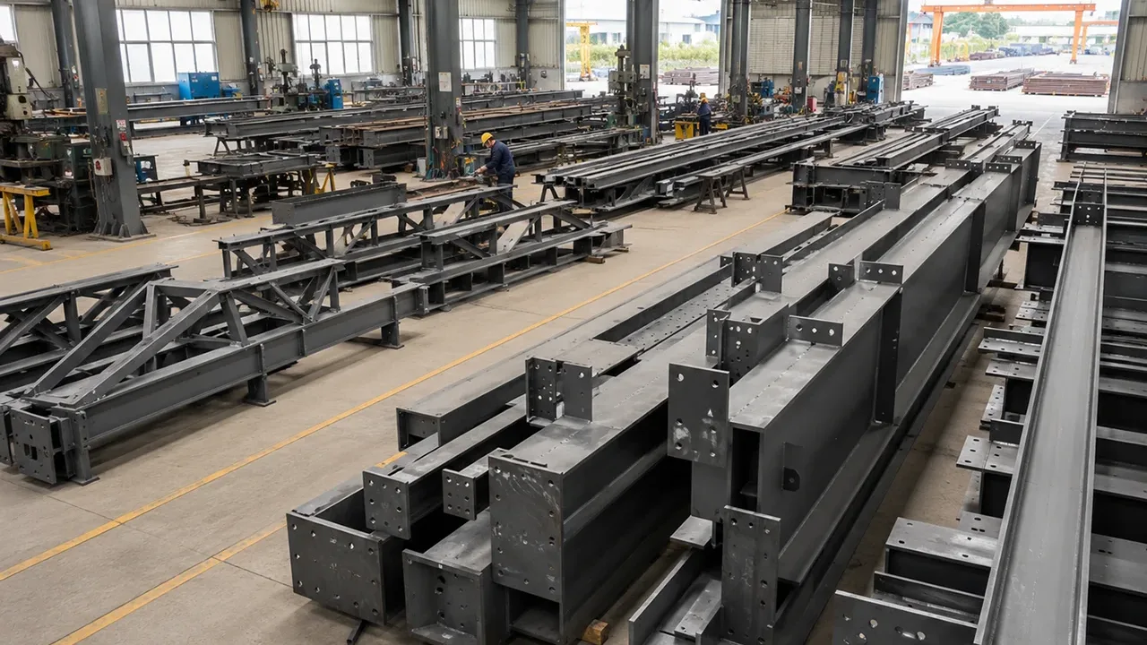
A well-managed Steel structure factory can control cutting accuracy, hole positioning, fit-up, welding procedures, heat input, distortion, and inspection more consistently than uncontrolled field conditions.
XTD Steel Structure coordinates connection detailing with fabrication requirements so potential conflicts can be identified before components reach the construction site.
Trial Fit-Up and Inspection
Trial assembly and dimensional inspection can identify misalignment, hole-position problems, insufficient clearances, and other detailing issues before shipment.
Correcting these problems in the factory is generally more efficient than modifying structural components during erection.
How Engineers Should Check Weld and Bolt Capacity
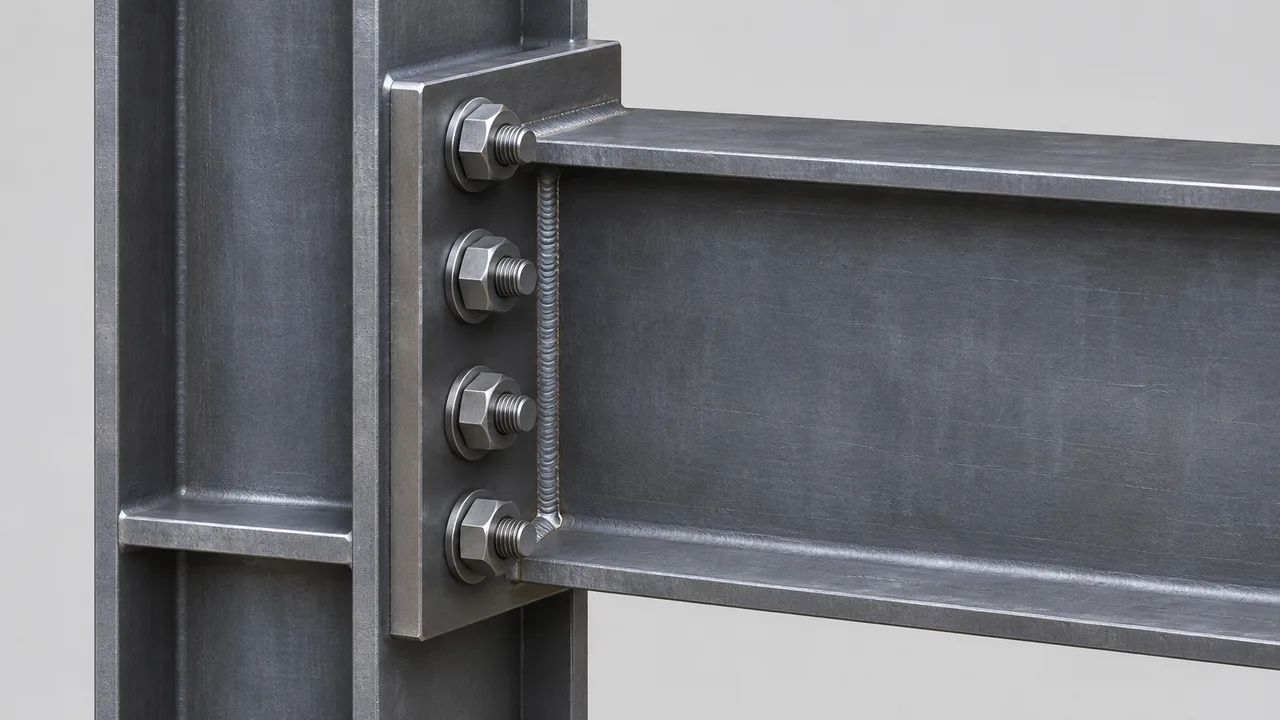
A systematic review helps reduce weld and bolt capacity mistakes and prevents designers from focusing on only one connection component.
-
- Determine all axial, shear, moment, torsional, and other applied forces.
- Define the complete load path through the connection.
- Identify any eccentricity between the applied load and the connection resistance center.
- Calculate the demand on the bolt group or weld group.
- Evaluate interaction between combined loads.
- Check individual bolt or weld resistance.
- Check plate bearing and tear-out.
- Check net-section fracture.
- Check block shear where applicable.
- Check base metal yielding and rupture.
- Check local bending and prying action where relevant.
- Review fabrication tolerances and fit-up requirements.
- Review installation access and erection conditions.
- Identify the governing limit state and confirm adequate connection resistance.
This approach evaluates the connection as one integrated system instead of treating the bolt or weld as the only component that matters.
Common Warning Signs of a Poor Connection Design
- Very large welds attached to relatively thin plates
- High-strength bolts combined with inadequate edge distances
- Bolt groups located far from the applied load line without eccentricity checks
- Thin end plates carrying high bolt tension
- No combined-load verification
- No checks for connected plate capacity
- Insufficient access for bolt installation or tightening
- Field welding specified in difficult or poorly controlled conditions
- Frequent hole modification required during erection
- Connection geometry that does not match the intended load path
These conditions do not automatically mean that a connection is unsafe, but they indicate areas that require closer engineering and fabrication review.
Frequently Asked Questions
What Is the Most Common Weld and Bolt Capacity Mistake?
One of the most common mistakes is checking only the nominal resistance of the bolt or weld while ignoring the rest of the connection. Plates, base metal, bolt-group geometry, weld-group geometry, eccentricity, and combined loading may control the actual resistance.
Can a Bolt Be Strong Enough but the Connection Still Fail?
Yes. The bolt may have adequate shear or tension resistance while the connected plate fails through bearing, tear-out, net-section fracture, block shear, or local deformation.
Can a Weld Be Too Large?
Yes. Increasing weld size may provide little structural benefit when the connected base metal already governs the design. Oversized welds can also increase heat input, distortion, fabrication time, and cost.
Why Does Eccentricity Reduce Connection Capacity?
Eccentricity creates an additional moment and produces nonuniform force distribution. Some bolts or weld segments may therefore carry substantially higher demand than indicated by a simple direct-load calculation.
Do Bolts in a Group Always Carry Equal Loads?
No. Load distribution depends on bolt layout, stiffness, deformation, eccentricity, and the type of loading. The most heavily loaded bolt may carry significantly more force than the average bolt.
Why Must Weld and Bolt Capacity Be Checked Under Combined Loads?
Because tension, shear, moment, torsion, and eccentric loading can act simultaneously. A connection that satisfies each individual check may still become inadequate when these forces interact.
Conclusion
Weld and bolt capacity mistakes usually occur when connection design is reduced to checking an individual fastener instead of evaluating the complete structural system. Bolt strength, weld resistance, plate capacity, base metal behavior, eccentricity, combined loading, connection geometry, fabrication quality, and installation conditions must all work together.
Reliable connections require a clear load path and balanced resistance between every component involved in force transfer. Stronger bolts or larger welds cannot compensate for weak plates, poor detailing, excessive eccentricity, inaccurate fabrication, or impractical erection conditions.
By coordinating structural design, detailing, fabrication, inspection, and installation, engineers and fabricators can reduce field modifications, avoid unnecessary material, and produce connections that perform as intended throughout the service life of the steel structure.