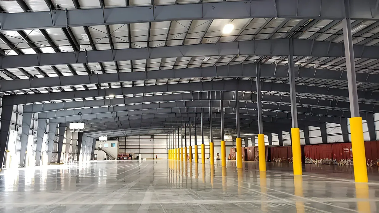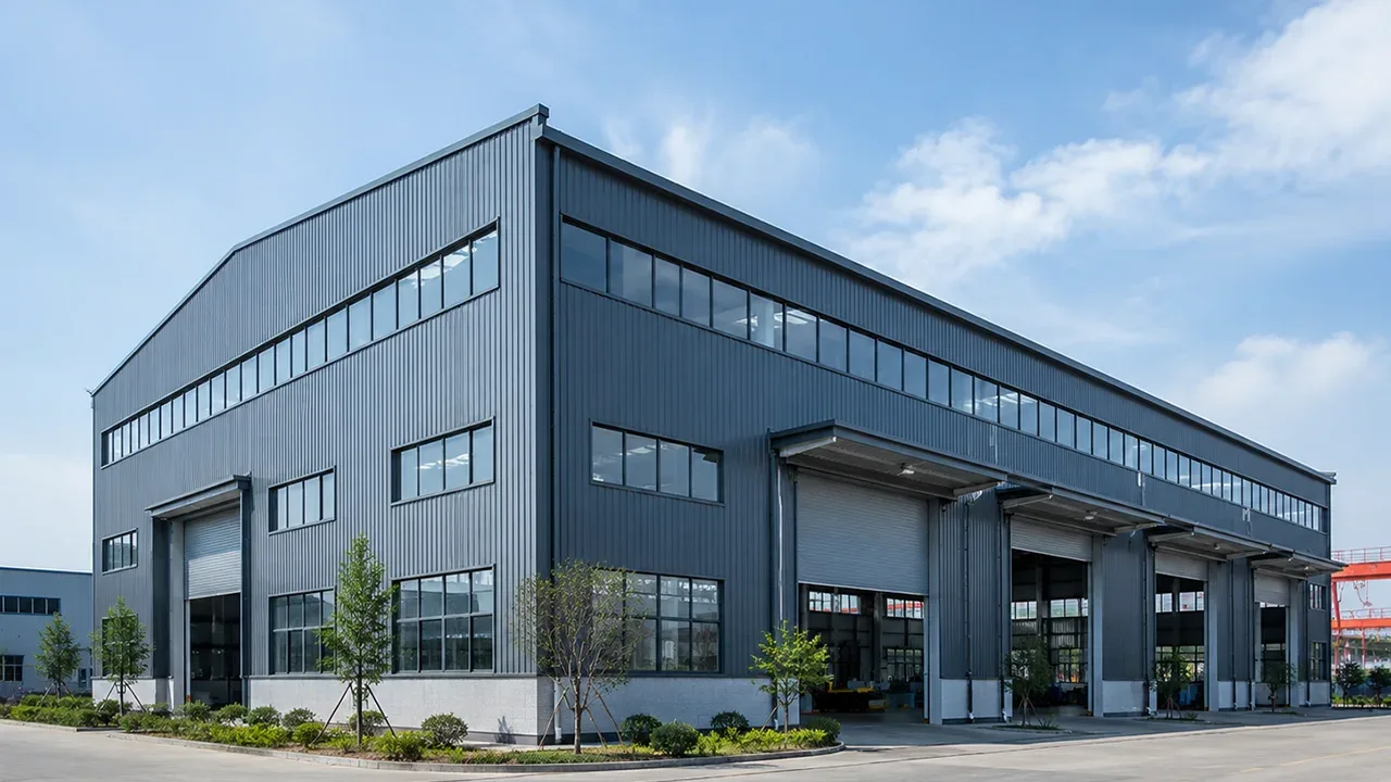
In steel building design, some forces bend a member, some forces push sideways, and some forces act directly along the length of the member. These lengthwise forces are known as axial loads. They are especially important in columns, truss members, braces, tie rods, struts, tower members, and space truss systems where the main structural action is either compression or tension.
When axial force is properly understood, engineers can select the right member size, connection type, bracing layout, and fabrication detail. When it is ignored or underestimated, a steel member may buckle, stretch, deform at the connection, or transfer force into parts of the structure that were not designed to resist it. For this reason, axial load behavior is a basic but critical part of safe and efficient steel structure design.
What Are Axial Loads?
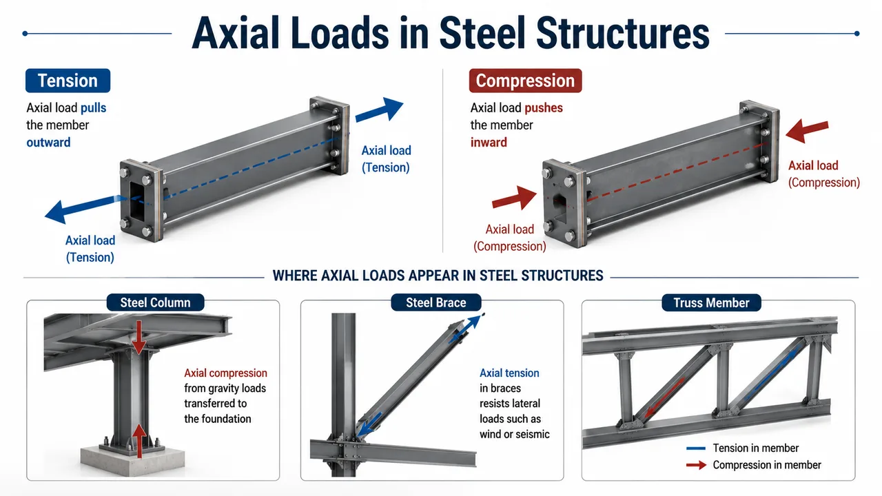
Axial loads are forces that act along the longitudinal axis of a structural member. In simple terms, the force travels in the same direction as the member length. If the force pulls the member apart, it creates tension. If the force pushes the member together, it creates compression.
Unlike bending loads, which cause a beam to curve, axial force is mainly related to direct stress along the member. A perfectly centered axial force creates a more uniform stress distribution across the section. In real steel structures, however, members may also experience small eccentricities, connection offsets, secondary bending, or installation tolerances. That is why engineers do not only look at the load value, but also at the member geometry, support condition, connection detail, and overall load path.
Common Steel Members That Carry Axial Force
Many steel members are designed primarily to resist axial force. These include columns, diagonal braces, roof truss members, tower legs, hanger rods, tie members, struts, and space truss components. In industrial buildings, axial force often appears in bracing systems, portal frame columns, truss chords, roof supports, crane-related framing, and stabilizing members that keep the building aligned under wind, seismic, and operational loads.
Tension Axial Loads in Steel Members
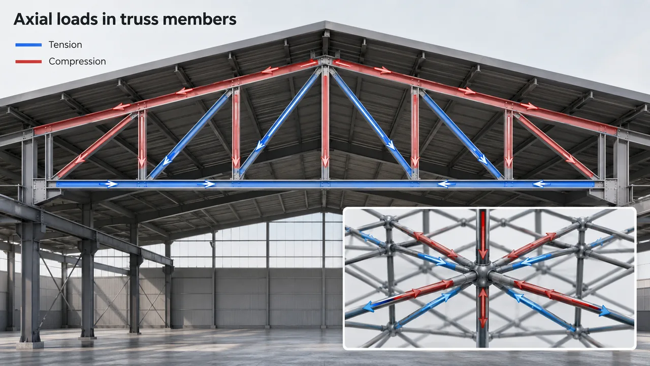
Tension happens when a member is pulled along its length. A steel tie, hanger, brace, or truss member under tension is being stretched by the applied force. Steel performs very well in tension because of its high tensile strength and ductility, but the member and its connections must still be designed carefully.
In a tension member, engineers usually check the gross section yielding, net section fracture, bolt hole reduction, weld capacity, plate tearing, and connection detailing. Even if the main steel member has enough strength, the connection may become the weak point if the force is not transferred properly.
Examples of Members Under Tension
In roof trusses, bottom chord members often carry tension under gravity loads. Diagonal web members may also switch between tension and compression depending on load direction and truss geometry. Bracing rods or angles in wall and roof systems commonly resist tension when wind or lateral forces act on the building. In suspension-type details, hanger rods and tie bars are also typical tension members.
The main design goal for a tension member is to make sure the force can travel continuously from one part of the structure to another without causing plate rupture, bolt failure, weld failure, or excessive elongation.
Compression Axial Loads in Steel Members
Compression happens when a member is pushed along its length. A steel column supporting roof loads, a strut resisting frame movement, or a truss chord carrying downward roof force may all work as compression members. Compression design is more sensitive than tension design because the member can fail by buckling before the steel reaches its full material strength.
For compression members, the shape and length of the member are just as important as the steel grade. A short, compact member can carry high compression force. A long and slender member may become unstable under a much smaller load. This is why compression design always considers buckling, slenderness ratio, end restraint, lateral support, and effective length.
Why Buckling Matters
Buckling is a stability failure where a compression member bends sideways under load. It is not always caused by weak steel. A member may buckle because it is too long, too slender, poorly braced, or connected in a way that allows excessive rotation. Once buckling starts, the member loses capacity quickly and may cause load redistribution to nearby members.
For example, a roof truss compression chord needs proper lateral restraint from purlins or bracing. A steel column may need base plate stability, anchor bolt design, and intermediate restraint from beams or wall systems. A diagonal strut must be checked not only for axial force but also for its unsupported length and connection eccentricity.
Axial Loads vs Shear Loads and Moment Loads
Axial force is only one type of structural action. In real steel buildings, members may experience axial force, shear, bending moment, torsion, or a combination of these effects. Understanding the difference helps engineers choose the correct design approach.
Axial Load
An axial load acts along the member length. It may pull the member in tension or push it in compression. Columns, braces, truss members, and tie rods are common examples of members where axial behavior is important.
Shear Load
A shear load acts perpendicular to the member axis. It tries to slide one part of the member relative to another. Beam webs, bolts, welds, and connection plates often need shear checks.
Moment Load
A moment load causes bending. Beams, rafters, portal frames, and cantilever members often resist bending moments. In many steel frames, axial force and bending moment occur together, especially in columns and rigid frame members.
How Axial Loads Work in Steel Trusses and Space Truss Systems
Trusses are efficient because their members are arranged so that many forces are carried mainly as tension or compression rather than heavy bending. This makes truss systems suitable for long-span roofs, industrial buildings, stadium structures, workshops, warehouses, and transportation facilities.
In a typical roof truss, the top chord may carry compression under gravity loads, while the bottom chord may carry tension. Web members transfer force between the chords and may carry either tension or compression depending on the truss type, support layout, and loading condition. The overall system works because the members form a stable triangular arrangement that channels force through direct axial action.
Axial Load Flow in a Space Truss
A space truss distributes load in three dimensions instead of only one plane. This allows force to travel through multiple connected members, improving stiffness and load sharing across a wider structural area. In large roofs, canopies, terminals, halls, and public buildings, a space truss can reduce unsupported spans while keeping the structure relatively lightweight.
Because each member in a space truss may carry different tension or compression force, accurate analysis and precise connection fabrication are important. Joint geometry, bolt arrangement, node design, and installation accuracy all influence how axial force moves through the system.
Key Design Factors for Axial Load Members
Designing members for axial loads is not only about selecting a steel section with enough area. Engineers must also consider member length, section shape, boundary condition, material strength, and the surrounding structural system.
Member Length and Slenderness
Slenderness is one of the most important factors for compression members. A long, thin member is more likely to buckle than a short, compact member. This is why bracing layout, purlin spacing, frame spacing, and intermediate restraint points must be coordinated during structural design.
Cross-Section Shape
Different steel sections behave differently under axial force. H-sections are common for columns and frame members. Tubes provide good compression performance in multiple directions. Angles and channels are often used in bracing and truss web members. Built-up sections may be selected for heavy-duty industrial structures where standard sections are not enough.
End Conditions and Support Restraint
A member with fixed or restrained ends usually performs differently from a member with pinned ends. The degree of rotational restraint affects effective length and buckling capacity. For this reason, connection design and member design cannot be separated.
Material Strength
Steel grade affects yield strength and tensile capacity, but higher material strength does not automatically solve every design issue. A high-strength slender compression member may still buckle if it is not properly restrained. Material selection must work together with member geometry and structural layout.
Connection Design for Axial Loads
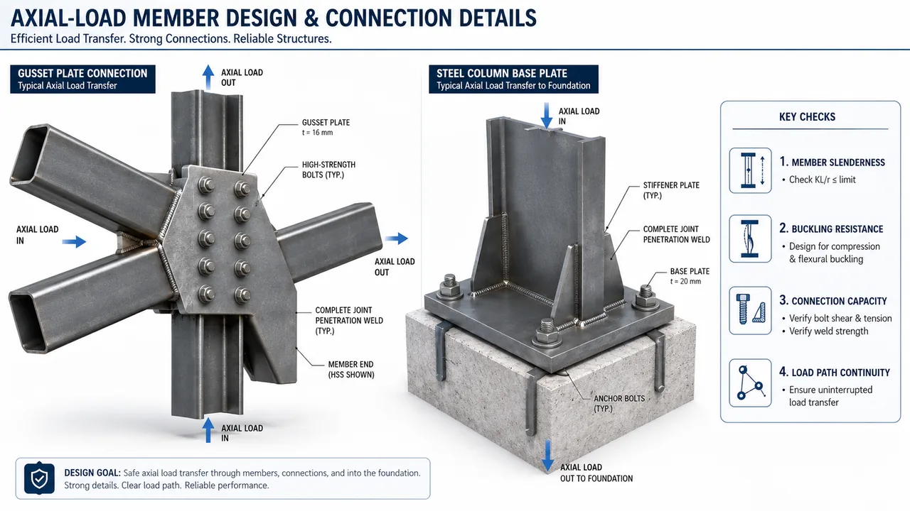
Axial force must pass through connections safely. A member may be strong enough, but if the bolts, welds, gusset plates, end plates, or base plates are not designed correctly, the load path can fail at the joint.
For a complete building system, axial force checks should be coordinated with the overall steel structure design, including member sizing, connection detailing, fabrication, transportation, and installation.
Tension Connection Requirements
In tension connections, engineers check bolt shear, bolt tension, weld strength, net section fracture, block shear, plate tearing, and hole layout. The connection must allow the tensile force to transfer smoothly without creating unnecessary eccentricity or stress concentration.
Compression Connection Requirements
Compression connections often require proper bearing, stiffeners, plate contact, weld continuity, and local buckling control. Base plates under columns must distribute compression force into the foundation, while truss and brace connections must prevent local deformation around the joint.
Failure Risks Caused by Poor Axial Load Design
Poor axial load design can create serious structural problems. A compression member may buckle. A tension member may fracture at a weakened section. A gusset plate may deform. A bolt group may fail. A weld may crack. A column base may rotate or crush the supporting plate. These failures can reduce the capacity of the entire system.
Another risk is unintended load redistribution. When one member cannot carry its force, the load may move into adjacent members that were not designed for that demand. In a truss, this can change the force pattern across multiple members. In a braced steel building, it can reduce lateral stability. In a roof system, it can create excessive deflection or connection stress.
How XTD Steel Structure Handles Axial Load Requirements
XTD Steel Structure approaches steel building projects by connecting engineering design, fabrication quality, and installation control. This is important because axial force performance depends on more than calculation. The real structure must match the design assumptions.
For warehouses, factories, industrial buildings, roof trusses, platforms, and long-span systems, member sizing must be coordinated with joint detailing, bracing arrangement, fabrication tolerance, and erection sequence. A compression member needs correct restraint. A tension member needs a reliable load path. A truss system needs accurate node geometry. A steel frame needs connections that transfer force without unexpected deformation.
By considering these requirements from design through fabrication and site installation, XTD Steel Structure helps clients build steel structures that are strong, practical, and suitable for long-term use.
Practical Checklist for Reviewing Axial Load Members
Before finalizing a steel structure design, engineers and project teams should review the main axial force conditions carefully. A practical checklist includes:
- Identify whether each critical member is in tension, compression, or load reversal.
- Check axial force values from structural analysis.
- Review member length, slenderness, and unsupported segments.
- Confirm section capacity for tension or compression.
- Check buckling resistance for compression members.
- Review bolt, weld, plate, and gusset connection capacity.
- Confirm bracing and restraint conditions.
- Check whether eccentricity creates secondary bending.
- Coordinate fabrication dimensions with connection geometry.
- Verify that the installed structure matches the intended load path.
FAQ About Axial Loads in Steel Structures
What are axial loads in steel structures?
Axial loads are forces that act along the length of a steel member. They can place the member in tension when pulling outward or compression when pushing inward.
What is the difference between tension and compression axial loads?
Tension pulls a member apart, while compression pushes a member together. Steel members often perform well in tension, while compression members require careful buckling checks.
Why are compression members more sensitive to buckling?
Compression members can become unstable if they are too slender or poorly restrained. Buckling may occur before the steel reaches its full material strength.
Do truss members carry axial loads?
Yes. Most truss members are designed mainly to carry axial tension or compression. This is one reason trusses are efficient for long-span steel roof systems.
How do axial loads affect steel structure connections?
Axial force must transfer through bolts, welds, plates, gusset connections, base plates, and other joint details. If the connection is weak, the member strength alone is not enough to ensure structural safety.