When several structural members meet at one joint, the connection must transfer concentrated forces without creating an unnecessarily complicated load path. This challenge appears in braced steel frames, roof trusses, bridges, industrial platforms, towers, and many other structures. A properly developed gusset plate design provides the strength, geometry, and connection area required to move forces safely between braces, truss members, beams, columns, and supporting joints.
Designing a gusset plate involves more than selecting a steel plate with sufficient thickness. Engineers must consider axial tension and compression, shear, local bending, buckling, bolt or weld capacity, member alignment, fabrication tolerances, installation access, and environmental exposure.
This guide explains the main design workflow, common strength checks, connection methods, and detailing requirements for gusset plates used in braced frames and steel truss structures.
What Is Gusset Plate Design?
A gusset plate is a flat steel plate used to connect two or more structural members. In braced frames, it commonly connects diagonal braces to beams, columns, or beam-column joints. In steel trusses, it may connect chords, diagonals, vertical members, and secondary bracing at a common panel point.
Gusset plate design is the process of determining the plate material, dimensions, thickness, geometry, bolt arrangement, weld configuration, and supporting details required to transfer structural forces safely.
A typical gusset plate connection may include:
- A steel plate with a project-specific shape
- Diagonal braces or truss members
- Supporting beams, columns, or chords
- Structural bolts, welds, or both
- Connection angles or splice plates
- Stiffeners where local member strength is insufficient
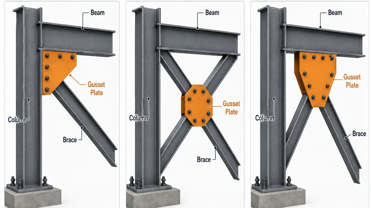
Common configurations include single-brace connections, X-bracing, V-bracing, inverted V-bracing, brace-to-column joints, brace-to-beam joints, and multi-member truss connections.
How Forces Travel Through a Gusset Plate
Force Transfer in Braced Frames
Braced frames resist wind, seismic action, crane movement, and other lateral forces. When a lateral load enters the building, the braces develop axial tension or compression. These brace forces pass through bolts or welds into the gusset plate and then into the connected beam, column, or structural joint.
A clear load path generally follows this sequence:
- The building receives a lateral load.
- The diagonal brace develops axial force.
- Bolts or welds transfer the force into the gusset plate.
- The plate distributes the force across its effective area.
- The supporting beam or column transfers the load toward the foundation.
Force Transfer in Steel Trusses
In a steel truss, roof, floor, wind, equipment, or bridge loads enter the structural system and create axial forces in chords, diagonals, and vertical members. The gusset plate transfers these forces between members at each panel point.
Unlike a simple brace connection, a truss joint may receive forces from several directions at the same time. The plate geometry and connection layout must maintain equilibrium while avoiding excessive eccentricity or localized deformation.
Tension, Compression, and Shear Effects
A gusset plate may experience several actions simultaneously:
- Tensile yielding across the gross plate section
- Fracture through the reduced net section
- Compression buckling in unsupported plate areas
- Block shear around bolt groups
- Bearing deformation around bolt holes
- Local bending caused by eccentric force transfer
- Shear transfer between connected members
The final plate should be checked for all relevant limit states rather than being designed for only one force condition.
Information Required Before Starting Gusset Plate Design
Connection design should begin with reliable structural-analysis data. Important inputs include:
- Factored tension and compression forces
- Governing load combinations
- Member sizes, shapes, and orientations
- Brace or truss geometry
- Steel grades
- Bolt and weld requirements
- Installation and inspection clearances
- Environmental exposure conditions
- Applicable structural design standards
Establishing the Connection Work Point
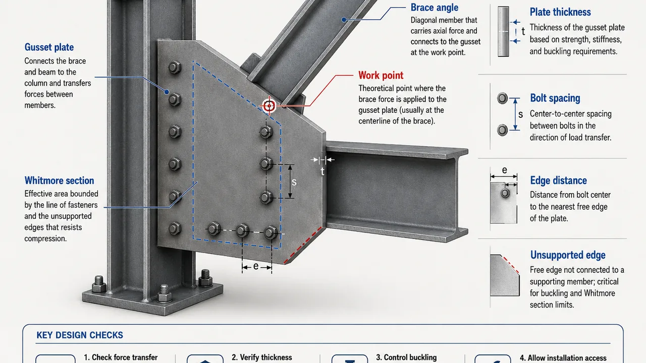
The connection work point is the theoretical intersection of the centerlines of the connected members. Aligning brace, beam, column, or truss-member centerlines near this point creates a more direct load path and reduces secondary bending.
When exact alignment is not practical, the resulting eccentricity should be included in the connection calculations. It should also be clearly represented in structural and fabrication drawings.
Determining the Governing Load Case
The most critical load case may not be the largest axial force considered alone. Designers should evaluate dead, live, wind, seismic, crane, machinery, construction-stage, and load-reversal conditions where applicable.
Connections exposed to seismic loading, vibration, or moving loads may also require checks for cyclic behavior, fatigue, and repeated force reversal.
Selecting Gusset Plate Material
Steel Grade and Mechanical Properties
The selected steel should provide appropriate yield strength, tensile strength, ductility, toughness, and weldability. The material grade should also be compatible with the braces, beams, columns, or truss members connected to the plate.
Higher-strength steel can reduce the required plate area in some cases, but it does not automatically resolve buckling, welding, fabrication, or connection-stiffness concerns.
Environmental and Corrosion Conditions
Indoor dry environments may require only a standard protective coating. Exterior, coastal, industrial, or chemically aggressive conditions may require more extensive corrosion protection.
Designers should consider:
- Paint or protective coating systems
- Hot-dip galvanizing
- Drainage around connection interfaces
- Moisture-trapping gaps
- Access for future inspection and maintenance
Determining Gusset Plate Geometry
Plate Length and Width
The plate must provide enough area for bolts or welds while maintaining adequate distances from holes and welds to plate edges. Its dimensions should also allow force to spread into the supporting frame without creating abrupt stress concentrations.
Plate length and width are influenced by the brace angle, bolt-group dimensions, weld lengths, available joint space, and installation requirements.
Brace and Truss-Member Angles
Member angles influence the shape of the plate and the direction of force transfer. Poor coordination can introduce eccentricity, reduce available weld length, or produce an inefficient bolt arrangement.
The plate should accommodate the actual member orientation shown in the structural model and fabrication drawings.
Free Edges and Unsupported Areas
Long unsupported projections can reduce compression resistance and increase the risk of out-of-plane buckling. Plate geometry should minimize unnecessary free edges and provide suitable restraint near highly compressed areas.
Where required, engineers may increase plate thickness, reduce the unsupported region, modify the plate shape, or add stiffening.
Avoiding Stress Concentrations
Sharp re-entrant corners, abrupt changes in plate width, crowded bolt groups, and poorly terminated welds can create localized stress concentrations. Smooth transitions and practical fabrication details help improve force distribution and connection reliability.
How to Determine Gusset Plate Thickness
There is no single standard thickness suitable for every connection. Plate thickness depends on force demand, steel strength, effective width, connection type, unsupported length, and applicable failure modes.
An excessively thin plate may yield, fracture, tear, or buckle. However, an unnecessarily thick plate increases material cost, weld size, heat input, fabrication difficulty, and connection stiffness.
Thickness for Tension Resistance
For tension loading, the designer should check:
- Gross-section yielding
- Net-section fracture through bolt holes
- Block shear around the bolt group
- Plate bearing at bolt holes
- Edge tear-out
The remaining steel area after deducting bolt holes must be sufficient to carry the required tensile force.
Thickness for Compression Resistance
Compression resistance is influenced by the effective plate width, unsupported length, boundary restraint, plate thickness, and force direction. A plate that is adequate in tension may still buckle when subjected to compression.
The designer should evaluate both the strength of the material and the stability of the unsupported plate region.
Thickness for Shear and Bending
Shear and local bending may develop where forces enter the plate eccentrically or where several members meet at one joint. Out-of-plane forces and combined stresses should also be considered where they are part of the actual connection behavior.
Understanding the Whitmore Section
The Whitmore section is an effective width used to evaluate how force spreads through a gusset plate. The force is assumed to distribute outward from the ends of the connected bolt group or weld arrangement.
This effective section is commonly used when checking tensile yielding and compression behavior. Its width depends on the geometry of the connection and the distance between the connected member and the critical plate section.
Whitmore Section in Tension
For tension checks, the effective width is used to calculate the average tensile stress in the plate. The resulting section is evaluated for yielding, while bolt holes crossing a critical fracture path may also reduce the available net area.
Whitmore Section in Compression
For compression, the Whitmore section helps define the effective compression area. The designer must also determine an appropriate buckling length based on the supported and unsupported portions of the plate.
Bolted Gusset Plate Design
Selecting Bolts
Bolt selection depends on the required force transfer, plate thickness, connected-member geometry, and installation method. Important factors include:
- Bolt diameter and grade
- Number of bolts
- Single-shear or double-shear behavior
- Bearing-type or slip-critical connection requirements
- Bolt tightening and inspection procedures
Bolt Spacing and Edge Distance
Adequate spacing allows forces to distribute between bolts and provides room for installation. Proper end and edge distances reduce the risk of tear-out, block shear, and localized plate damage.
The final layout should also include practical fabrication tolerances and space for tightening equipment.
Bolt-Group Layout
A symmetrical bolt group aligned with the member centerline generally supports more direct force transfer. Highly eccentric or congested layouts may increase local stresses and complicate installation.
Checks for Bolted Connections
Typical bolted-connection checks include:
- Bolt shear strength
- Plate and member bearing resistance
- Net-section fracture
- Block shear
- Edge tear-out
- Slip resistance where required
Welded Gusset Plate Design
Weld Type and Arrangement
Gusset plates may use fillet welds, groove welds, or a combination of weld types. Welds can connect the plate to braces, beams, columns, chords, diagonals, or other supporting members.
Shop welding generally provides better control of positioning, environmental conditions, and inspection than field welding.
Determining Weld Size and Length
The weld must provide sufficient effective area to transfer the required force. Weld size and length should reflect force direction, eccentricity, base-metal strength, and the actual connection geometry.
Providing a very large weld does not always improve the connection. Excessive welding can introduce high heat input, residual stress, and distortion.
Fabrication Considerations
Welded connections require control of:
- Heat input
- Welding sequence
- Residual stress
- Plate and member distortion
- Access for welding and inspection
- Qualified procedures and personnel
Combined Bolted and Welded Connections
A common fabrication strategy is to weld the gusset plate to the main frame in the workshop and bolt the brace or truss member to the plate during site assembly. This method is widely used in prefabricated steel structures because it combines controlled shop welding with efficient field erection.
| Consideration | Bolted Connection | Welded Connection |
|---|---|---|
| Fabrication method | Requires drilling or punching | Requires controlled welding |
| Site installation | Generally faster | More dependent on site conditions |
| Adjustability | Allows limited erection adjustment | More difficult to modify |
| Inspection | Bolt layout and tightening are checked | Weld size and quality are checked |
| Net-section reduction | Created by bolt holes | No bolt-hole reduction |
| Heat distortion | Minimal | Must be controlled |
| Typical application | Field-assembled members | Shop-fabricated joints |
Gusset Plate Design for Braced Frames
Concentrically Braced Frames
In a concentrically braced frame, the centerlines of braces, beams, and columns should meet close to a common work point. This arrangement supports direct tension and compression transfer while reducing unnecessary bending.
A complete gusset plate braced connection should coordinate the brace, plate, bolts or welds, supporting beam or column, and any required stiffeners as one continuous force-transfer system.
X-Bracing Systems
X-bracing uses two diagonal braces crossing within one structural bay. Depending on the arrangement, the braces may connect through separate gusset plates or share a central connection.
Designers should consider force reversal, installation sequence, connection congestion, and the interaction between crossing members.
Chevron and V-Bracing Systems
In chevron or V-bracing systems, two braces meet at a beam. Their forces can introduce a significant vertical component into the beam, particularly when one brace yields or buckles before the other.
The gusset plate, supporting beam, and any beam stiffeners should be designed together.
Seismic Braced Frames
Seismic bracing connections may experience repeated tension and compression cycles. The brace may be expected to yield in tension and buckle in compression while the connection remains capable of transferring the required forces.
Seismic detailing should provide:
- A ductile load path
- Adequate connection strength
- Rotation clearance for brace buckling
- Control of brittle fracture
- Reliable bolt and weld behavior under cyclic loading
- Capacity-based connection resistance where required
Gusset Plate Design for Steel Truss Structures
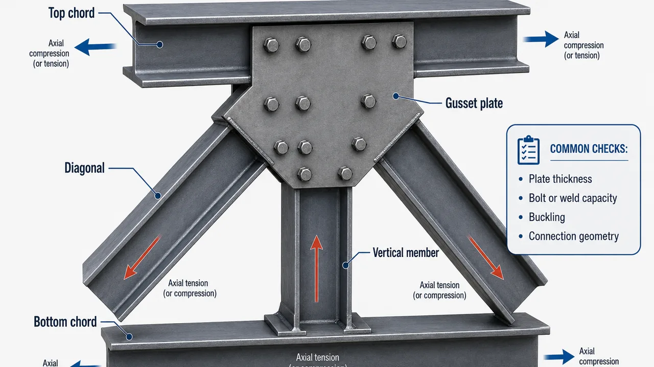
Truss Panel-Point Connections
At a truss panel point, chords, diagonals, and vertical members may meet at one plate. Each member can introduce a different axial force and direction.
The connection should satisfy force equilibrium while providing enough plate area for bolts or welds, proper edge distances, and practical member spacing.
Roof Trusses
Roof-truss gusset plates transfer gravity, wind-uplift, and sometimes equipment loads. Their design should account for fabrication, transport, lifting, shop assembly, and site splicing requirements.
Bridge Trusses
Bridge-truss connections may carry high axial forces and repeated traffic loading. Large bolt groups, fatigue-sensitive details, corrosion protection, and long-term inspection access are therefore important considerations.
Industrial and Long-Span Trusses
Industrial trusses may support suspended equipment, conveyors, piping, ceilings, or maintenance platforms. Long spans and complex joint geometry can produce large connection forces and require heavy bolted or welded gusset plates.
Accurate detailing and fabrication control are essential to ensure that all members fit correctly during assembly.
Common Gusset Plate Failure Modes
Gross-Section Yielding
Gross-section yielding causes permanent deformation when tensile stress exceeds the plate’s yield resistance.
Net-Section Fracture
Net-section fracture occurs through bolt holes when the remaining steel area is insufficient to resist the tensile force.
Block Shear Failure
Block shear combines tension and shear failure around a bolt group, potentially tearing a block of steel from the plate.
Bolt Shear and Bearing Failure
Bolts may fail in shear, while excessive bearing pressure may deform the plate around the bolt holes.
Weld Failure
Weld failure may result from insufficient weld size, length, penetration, orientation, or fabrication quality.
Compression Buckling
Thin plates and long unsupported areas may deform out of plane when subjected to compression.
Edge Tear-Out
Insufficient distance between a bolt hole and the plate edge may allow the steel to tear.
Fatigue and Repeated Loading
Bridges, crane structures, towers, and vibrating industrial structures may experience repeated stress cycles. Smooth force paths, controlled geometry, and reliable fabrication details help reduce fatigue-sensitive stress concentrations.
Fabrication and Detailing Requirements
Fabrication Drawings
Detailed drawings should clearly indicate:
- Plate dimensions and thickness
- Steel material grade
- Bolt diameter, grade, spacing, and hole size
- Weld size, type, length, and location
- Work-point dimensions
- Member angles
- Surface-treatment requirements
Cutting and Hole Preparation
Gusset plates may be produced using CNC plasma cutting, laser cutting, flame cutting, drilling, or punching. Plate edges and bolt holes should meet the specified dimensional tolerances.
Tolerance and Fit-Up Control
Fabrication teams should verify hole alignment, member angles, plate positioning, assembly gaps, and weld distortion. Accurate fit-up reduces forced assembly and helps maintain the intended load path.
XTD Steel Structure combines connection detailing with controlled cutting, drilling, welding, and dimensional inspection to support accurate steel-component fabrication before site delivery.
Inspection and Quality Control
Material Verification
- Confirm steel grade and material certificates.
- Verify plate thickness.
- Inspect surface condition and corrosion protection.
Bolt Inspection
- Verify bolt grade, diameter, and quantity.
- Check washers and installation orientation.
- Confirm tightening requirements.
- Inspect contact surfaces where slip resistance is required.
Weld Inspection
- Verify weld size and continuity.
- Check for cracks, porosity, undercut, and incomplete fusion.
- Conduct non-destructive testing where required.
Final Geometry Inspection
- Check work-point alignment.
- Verify brace or truss-member angles.
- Inspect plate deformation.
- Confirm member fit-up and overall joint geometry.
Common Gusset Plate Design Mistakes
Recurring design and detailing mistakes include:
- Selecting plate thickness without checking all failure modes
- Ignoring compression buckling
- Misaligning member centerlines
- Providing insufficient bolt spacing or edge distance
- Creating an overcrowded connection
- Providing inadequate welding access
- Ignoring fabrication and erection tolerances
- Using plates that are unnecessarily thick
- Restricting seismic-brace rotation
- Failing to coordinate structural and fabrication drawings
- Ignoring corrosion-prone interfaces
- Copying standard details without checking actual project forces
Practical Gusset Plate Design Workflow
- Determine member forces and governing load combinations.
- Establish the connection work point.
- Select the plate material.
- Develop preliminary plate geometry.
- Choose a bolted, welded, or combined connection.
- Determine the required plate thickness.
- Check yielding, fracture, block shear, bearing, and buckling.
- Design the bolts and welds.
- Check supporting beams, columns, chords, and stiffeners.
- Confirm installation and inspection access.
- Prepare complete fabrication details.
- Complete the final engineering review.
Frequently Asked Questions
What Is the Main Purpose of Gusset Plate Design?
The main purpose is to ensure that forces can transfer safely between braces, truss members, beams, columns, and structural joints without causing plate, bolt, weld, or supporting-member failure.
How Is Gusset Plate Thickness Determined?
Thickness depends on force demand, steel strength, plate geometry, unsupported length, bolt or weld layout, tension resistance, compression buckling, and other governing failure modes.
What Is the Whitmore Section in Gusset Plate Design?
The Whitmore section is an effective plate width used to evaluate how forces spread through the gusset plate. It is commonly considered when checking tensile yielding and compression behavior.
Are Gusset Plates Better Bolted or Welded?
Neither method is universally better. The appropriate choice depends on force demand, fabrication capacity, erection conditions, adjustability, inspection, transportation, and maintenance requirements.
Can One Gusset Plate Connect Several Truss Members?
Yes. Truss panel-point connections commonly use one plate to connect chords, diagonals, and vertical members. However, all force directions, connection components, and potential failure modes must be evaluated.
Why Do Gusset Plates Buckle?
Buckling can occur when compression acts through a thin plate with a long unsupported region. Insufficient edge restraint, poor geometry, and eccentric loading can increase the risk.
Conclusion
Gusset plate design integrates structural analysis, plate geometry, material selection, bolt or weld engineering, fabrication, and site installation. Its purpose is to create a reliable load path between braces, truss members, beams, columns, and structural joints.
Safe performance requires tension, compression, shear, buckling, bolt, weld, and supporting-member checks to be considered together. Accurate detailing, controlled fabrication, and proper installation help ensure that gusset plates perform reliably in braced frames and steel truss structures throughout the service life of the project.