Every steel structure must transfer different types of forces safely from the roof, floor, wall system, frame, and bracing into the foundation. In real buildings, these forces do not act separately. A warehouse frame, factory building, truss roof, or portal frame may experience compression, tension, shear, bending, and horizontal force at the same time. This guide explains axial shear moment and lateral loads as one connected design topic, not as isolated engineering terms.
To understand how a steel building stays stable, engineers first review the structural steel load path from roof framing, beams, columns, bracing, connections, base plates, anchor bolts, and foundations. When that load path is clear, each member can be designed for the correct force type, and each connection can transfer the required force without creating weak points in the structure.
Why Load Types Matter in Steel Structure Design
Steel structure design is not only about choosing larger beams or heavier columns. The real question is what type of force each member carries and how that force moves through the full building system. A beam may carry vertical loading and develop shear near its supports. The same beam may also develop bending moment at midspan. A column may carry axial compression while resisting frame bending from wind or crane movement. A brace may transfer lateral load mainly as axial tension or compression.
Connections are just as important as the members themselves. Bolts, welds, gusset plates, end plates, base plates, and anchor bolts must be designed to transfer the same forces that the steel members carry. If the member is strong but the connection is weak, the building still has an unsafe load path.
What Are Axial Loads?
Axial loads act along the length of a structural member. When the force pushes the member inward, it is compression. When the force pulls the member outward, it is tension. Axial force is common in columns, bracing members, truss chords, truss web members, tie rods, and space truss elements.
Axial Compression
Axial compression is one of the most important design conditions for steel columns. A column transfers vertical force from the roof, floors, cranes, mezzanine systems, or supported framing into the foundation. Compression also appears in some braces, truss top chords, and web members. The main design risk is buckling, especially when the member is long, slender, or insufficiently restrained.
For compression members, engineers check the section size, material strength, unsupported length, effective length factor, and weak-axis behavior. A member may have enough steel area but still fail by instability if its slenderness is too high.
Axial Tension
Axial tension occurs when a member is pulled along its length. Tie members, cross bracing, bottom chords of roof trusses, and some diagonal web members often carry tension. Tension members are generally less sensitive to buckling, but they still require careful checks for net section area, bolt holes, weld capacity, plate tearing, and connection deformation.
Where Axial Loads Appear in Steel Buildings
Axial loads appear throughout steel structures. Columns transfer gravity loads downward. Bracing members convert lateral force into axial action. Truss members use tension and compression to span long distances efficiently. Anchor rods may carry tension when wind uplift acts on a roof system. Because axial forces are part of many structural systems, they must be coordinated with shear, moment, and lateral behavior.
What Are Shear Loads?
Shear loads act across a member or connection and tend to slide one part of the structure relative to another. In steel beams, shear is often highest near supports. In connections, shear may act through bolts, welds, end plates, clip angles, gusset plates, or bearing surfaces.
Shear Loads in Beams
When a beam supports roof panels, floor decking, crane runway loads, or mezzanine framing, the load creates internal shear. The web of the beam usually resists most of this shear. If the load is concentrated near a support or connection, engineers may also need to check web yielding, web crippling, or local buckling.
Shear is especially important in industrial buildings where loads may be heavy, concentrated, or repeated. Equipment platforms, conveyor supports, pipe racks, and crane systems can introduce strong local reactions that must be transferred safely through the beam and its connection.
Shear Loads in Connections
Connections often carry shear even when the connected members are designed mainly for bending or axial force. Bolts may resist shear across their shank. Welds may transfer shear along the weld line. End plates and clip angles may transfer beam reactions into columns or girders. A poorly detailed shear connection can deform, tear, or overload the supporting member.
What Are Moment Loads?
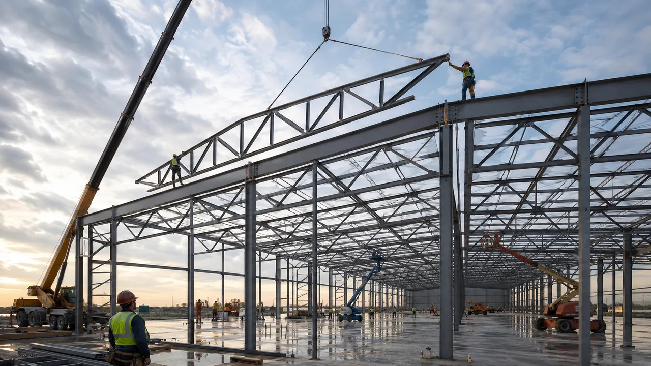
Moment loads create bending effects. A bending moment happens when a force acts at a distance from a support or connection, causing the member to rotate or curve. In steel buildings, moment commonly appears in beams, rafters, portal frames, cantilever brackets, crane supports, and rigid beam-column joints.
Moment design affects member depth, flange size, deflection control, joint stiffness, and connection detailing. A beam may be strong enough for shear but still fail serviceability requirements if deflection is too large. A frame may be stable under vertical loads but require stronger moment resistance under wind or crane movement.
Moment Loads in Portal Frames
Portal frames are widely used in warehouses, factories, workshops, and industrial buildings. In a portal frame, columns and rafters work together to resist vertical loads and lateral forces. Unlike a simple pinned system, a rigid frame develops bending moments at the knees, ridge, and base regions. These moment zones often control member sizing and connection design.
Moment Connections
Moment connections must transfer bending from one member into another. They may use extended end plates, flange plates, welded joints, high-strength bolts, stiffeners, and carefully designed bolt groups. These connections must resist rotation, flange force, web force, and local stress around the joint. If the connection is too flexible, the frame may not behave as assumed in the structural model.
What Are Lateral Loads?
Lateral loads act horizontally on a building. They can come from wind, seismic movement, crane surge, equipment vibration, wall pressure, or frame sway. For many steel buildings, lateral loads control bracing layout, frame stiffness, foundation reactions, roof diaphragm behavior, and connection design.
Wind Loads
Wind can create pressure on windward walls, suction on leeward walls, uplift on roof panels, and side forces on the full building frame. In lightweight steel buildings, wind uplift and lateral sway can become major design concerns. Roof bracing, wall bracing, purlins, girts, anchor bolts, and foundations must all work together to transfer wind effects safely.
Seismic Loads
Seismic loads come from ground movement and the dynamic response of the building mass. The structure must have a clear lateral force-resisting system to transfer seismic force into the foundation. Braced frames, moment frames, shear walls, diaphragms, and connection ductility may all affect seismic performance.
Crane and Equipment Loads
Industrial buildings may experience lateral force from overhead cranes, moving trolleys, conveyors, mechanical equipment, or vibrating machinery. These forces may act repeatedly and can affect columns, brackets, runway beams, bracing systems, and foundations. For factories and heavy-duty workshops, crane-related lateral loads must be included early in the design process.
How Axial Shear Moment and Lateral Loads Work Together
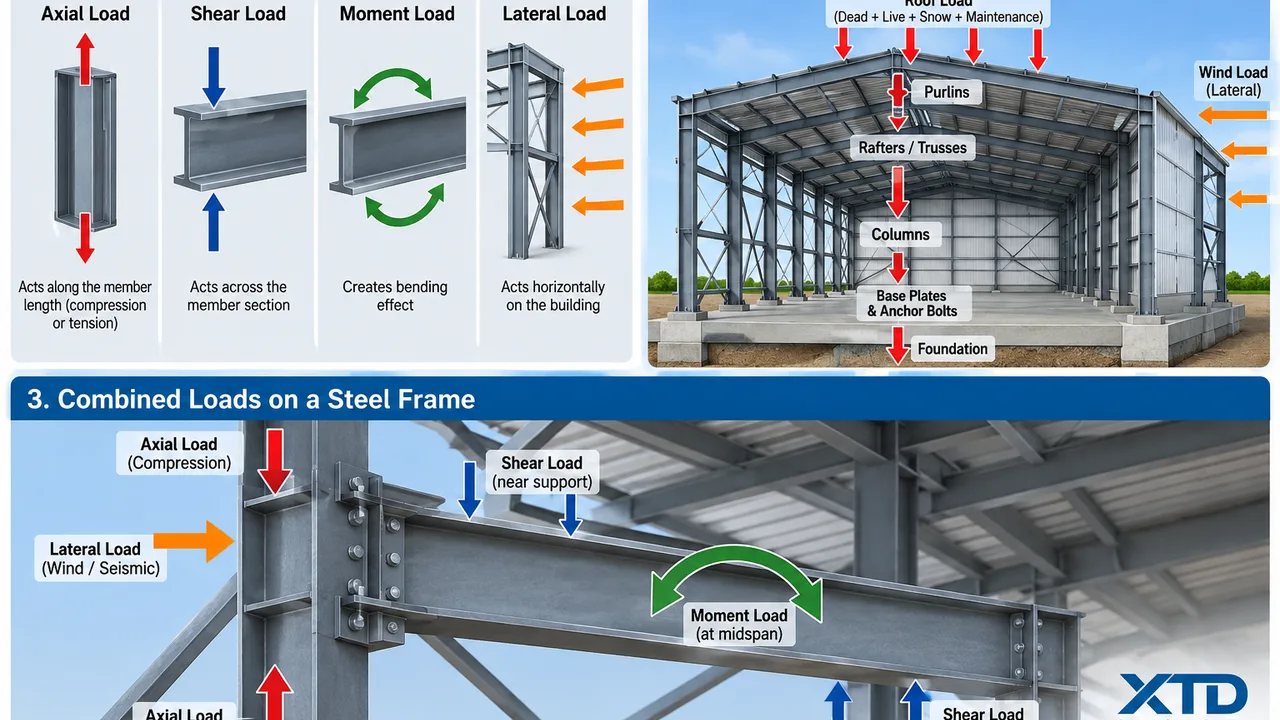
Axial shear moment and lateral loads rarely act alone in real steel structures. A column may carry axial compression from roof loads while also resisting bending from frame action. A beam may carry shear near the support and moment at midspan. A brace may receive lateral load from wind and transfer it as axial force. A base plate may need to transfer compression, shear, uplift, and moment into the foundation.
This combined behavior is why isolated member design can be risky. A beam, column, brace, or truss member should not be designed only as a single part. It must be checked as part of a complete system where force moves through multiple members and connections before reaching the foundation.
Load Behavior in a Steel Structure Warehouse
A steel structure warehouse is a practical example of how different load types work together. Roof dead load, roof live load, rain load, and maintenance load are first carried by roof panels and purlins. The purlins transfer these loads into rafters, beams, or trusses. These primary members then develop shear and moment as they span between supports.
Columns in a steel structure warehouse transfer axial compression from the roof frame into the foundation. At the same time, they may resist bending from wind pressure, frame sway, or crane reactions. Roof bracing and wall bracing transfer lateral loads to braced bays, while base plates and anchor bolts complete the load path into the concrete foundation.
When this system is properly coordinated, the warehouse behaves as one stable structure. When one part is overlooked, such as a weak brace connection or insufficient anchor bolt design, the entire load path may become unreliable.
Comparison of Main Load Types in Steel Structures
| Load Type | Main Direction | Common Members | Main Design Risk |
|---|---|---|---|
| Axial load | Along member length | Columns, braces, truss members | Buckling, yielding, connection failure |
| Shear load | Across member section | Beams, bolts, welds, plates | Web shear, bolt shear, local tearing |
| Moment load | Rotational or bending effect | Beams, rafters, rigid frames | Excessive deflection, flange stress, joint rotation |
| Lateral load | Horizontal direction | Bracing, frames, walls, columns | Sway, uplift, instability, foundation reaction |
Key Design Checks for Combined Loads
Member Strength
Each steel member must have enough capacity for the force it carries. Columns, beams, rafters, braces, truss members, and connection plates may all require different strength checks depending on whether they carry axial force, shear, moment, or combined loading.
Stability and Buckling
Compression members must be checked for buckling. This includes columns, compression braces, truss top chords, and slender web members. Lateral restraint, effective length, member slenderness, and connection stiffness all affect stability.
Deflection Control
Deflection is important for beams, roof framing, crane supports, platforms, and long-span structures. A member may be strong enough but still deflect too much under service loads. Excessive deflection can affect roof drainage, cladding alignment, crane operation, and occupant comfort.
Connection Capacity
Connections must transfer the same forces as the members. A shear connection must resist beam reactions. A moment connection must resist rotation and flange forces. A bracing connection must transfer axial force into the frame. A base connection must transfer compression, shear, uplift, and sometimes moment into the foundation.
Load Combination Review
Structural design must consider multiple load cases and combinations. Dead load, live load, wind load, seismic load, crane load, rain load, snow load, and erection load may not control the structure individually, but a combination of them may create the critical design condition.
Common Mistakes in Load Path Design
One common mistake is designing beams only for bending while ignoring shear near supports. Another is designing columns only for axial compression while ignoring bending from frame action. These simplified assumptions may work for basic examples, but real steel buildings often carry combined loads.
Lateral loads are also sometimes underestimated, especially in open industrial buildings or lightweight warehouse structures. Wind uplift, wall pressure, and frame sway can place high demand on bracing, anchor bolts, and roof connections. If the bracing system is not continuous, horizontal force may not reach the foundation safely.
Another mistake is treating pinned and rigid connections as if they behave the same way. A pinned connection allows rotation and usually transfers shear. A rigid or moment connection resists rotation and transfers bending. If the actual connection behavior does not match the design assumption, the frame may distribute force differently than expected.
Why Connections Are Critical for Load Transfer
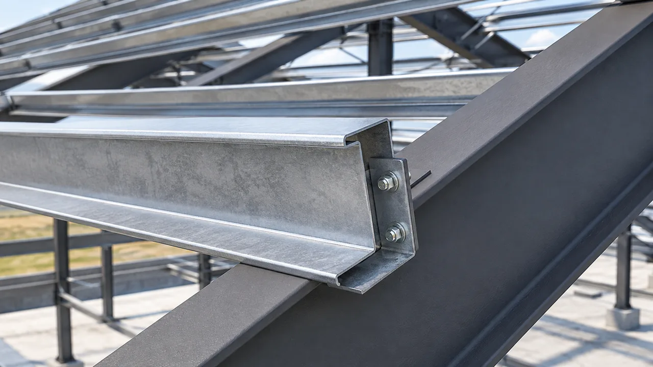
Every force in a steel building must pass through a connection. Bolts must resist shear, tension, or combined action. Welds must have enough size and length. Plates must have enough thickness and edge distance. Gusset plates must align with brace forces. Base plates must transfer compression and uplift into anchor bolts and foundations.
Connection design also affects constructability. A connection that looks correct in calculation may still cause problems if bolt access is poor, plate fit-up is difficult, or fabrication tolerance is too tight. For steel structures, good detailing must support both engineering performance and practical installation.
How XTD Steel Structure Supports Steel Load Design
For warehouses, factories, workshops, long-span roofs, and industrial steel buildings, XTD Steel Structure supports steel load design through structural coordination, member fabrication, connection detailing, workshop processing, quality inspection, and installation support. This helps ensure that member design and connection design work together instead of being treated as separate tasks.
By coordinating columns, rafters, beams, bracing, trusses, connection plates, and base details, XTD Steel Structure helps create a more reliable load path from the roof system to the foundation. This is especially important when axial shear moment and lateral loads must be checked together in one complete steel structure system.
Practical Takeaway for Steel Structure Projects
Safe steel buildings depend on understanding all major force types together. Axial force, shear, moment, and lateral force each affect different members, but they work as one integrated system through the load path. A strong member is not enough if the connection is weak. A good frame layout is not enough if the bracing system is incomplete. A stable roof is not enough if uplift cannot be transferred into the foundation.
A clear understanding of axial shear moment and lateral loads helps reduce design errors, improve fabrication coordination, and support safer long-term performance. For project owners, contractors, and engineers, this full-system view is one of the most important foundations of reliable steel structure design.
FAQ About Axial, Shear, Moment, and Lateral Loads
What Are Axial, Shear, Moment, and Lateral Loads?
They are the main force types in steel structures. Axial loads act along the member, shear loads act across the section, moment loads create bending, and lateral loads act horizontally on the building.
Which Members Carry Axial Loads?
Columns, bracing members, truss chords, truss web members, tie members, and many space truss elements commonly carry axial loads.
Where Do Shear Loads Usually Occur?
Shear loads commonly occur near beam supports, in bolts, welds, end plates, clip angles, gusset plates, and web areas of steel members.
Why Are Moment Loads Important in Steel Frames?
Moment loads create bending in beams, rafters, and rigid frame connections. They affect member size, deflection, joint stiffness, and frame stability.
How Do Lateral Loads Affect a Steel Building?
Lateral loads from wind, seismic movement, cranes, or equipment can cause sway, uplift, and horizontal reactions. Bracing and frame systems must transfer these forces safely to the foundation.