A Howe truss is a classic truss form that uses a clear arrangement of chords, vertical members, and diagonal members to transfer load across a span. It is often discussed in bridge history, but its structural logic is still useful for understanding steel trusses, roof systems, industrial buildings, and long-span support structures.
The main idea behind any truss is simple: instead of relying on one heavy beam, the structure uses connected triangles to carry load more efficiently. These triangles help control deformation and distribute forces through multiple members. In a Howe truss, the direction of the diagonals and the behavior of the verticals create a load path that is different from other well-known truss types such as Pratt or Warren trusses.
Choosing this truss type is not only about choosing a familiar shape. A project team needs to think about span length, load direction, member size, material choice, connection details, lateral bracing, fabrication method, transportation limits, and installation sequence. A truss can look simple in elevation, but its performance depends on how the entire system is designed and built.
This article explains how a Howe truss works, where it is commonly used, and what engineers, fabricators, and project owners should consider when applying this truss logic in steel building and bridge-related structures.
What Is a Howe Truss?
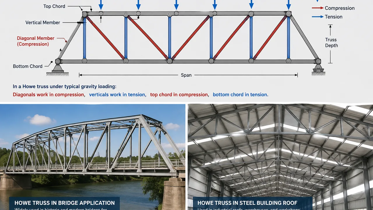
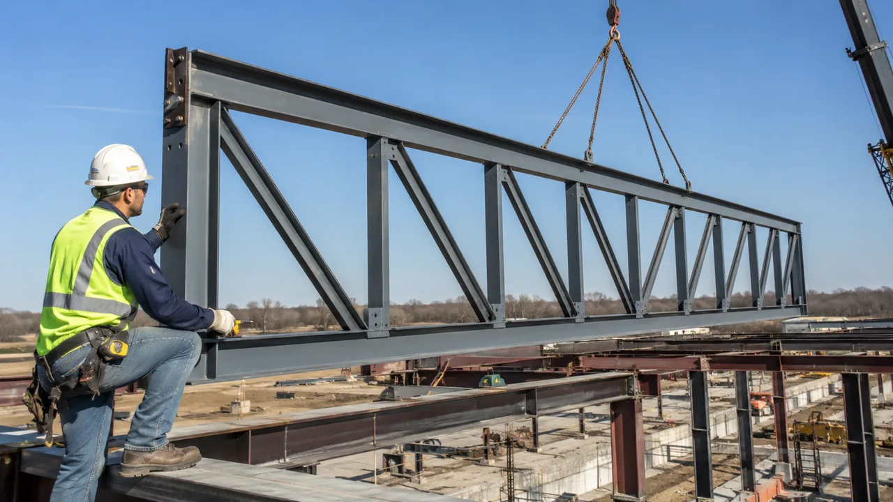
A Howe truss is a triangulated structural system made of top and bottom chords, vertical members, and diagonal members. The vertical and diagonal members divide the span into a series of panels. These panels help transfer load from the deck, roof, or supported surface toward the end supports.
The most recognizable feature of a Howe truss is the direction of its diagonal members. In a typical Howe arrangement, the diagonals slope downward toward the ends of the span from the center. This is opposite to the common Pratt truss arrangement, where diagonals usually slope downward toward the center.
Under typical gravity loading, the diagonal members in a Howe truss often work mainly in compression, while the vertical members often work in tension. This behavior was one reason the truss became historically important. In older bridge construction, timber could be used effectively for compression members, while iron rods could be used for tension members. That material combination made the truss practical for many early bridge structures.
In modern steel construction, the same historical material logic may not always control the design, because steel can perform well in both tension and compression when members are properly sized and braced. However, the force pattern still matters. Compression members must be checked for buckling, connection forces must be transferred safely, and lateral stability must be planned carefully.
How the Howe Truss Carries Load
A truss works by creating a clear load path. The load enters the structure through the roof, bridge deck, equipment platform, conveyor system, or other supported surface. From there, the load is transferred to panel points, then distributed through chords, vertical members, diagonal members, and finally into the supports.
The triangulated form is important because triangles are stable shapes. A rectangle can distort easily if it is not braced, but a triangle resists shape change more effectively. By dividing a span into triangular panels, a truss can carry loads with less material than a deep solid beam in many applications.
In a Howe truss, the load path is organized around the relationship between the chords, the verticals, and the diagonals. The top chord usually works as the upper compression path under common vertical loading. The bottom chord usually works as the lower tension path. The diagonals and verticals help move forces between these two main chords.
Top Chord and Bottom Chord
The top chord is the upper boundary of the truss. In many roof and bridge applications, it carries compression because the span bends under vertical load. This means the top chord must be sized not only for strength, but also for stability. A compression member can fail by buckling if it is too slender, even when the steel material itself has enough strength.
The bottom chord is the lower boundary of the truss. Under typical vertical loading, it often works in tension. This member helps tie the truss together and resists the spreading force created by bending action across the span. The bottom chord must be properly connected at panel points and splices so that tension can be transferred without weakness.
The distance between the top chord and bottom chord affects the depth of the truss. A deeper truss can often reduce member forces, but it may also create transportation, architectural, clearance, or installation challenges. A shallow truss may fit better into a building profile, but it may require heavier members to control stress and deflection.
Diagonal and Vertical Members
The diagonal members are one of the defining features of a Howe truss. Under common downward loading, these diagonals usually carry compression. Because compression members are sensitive to buckling, their length, section shape, bracing condition, and end connection details are important.
The vertical members often carry tension in the traditional Howe arrangement. Historically, this made sense because metal rods could act efficiently as vertical tension members while timber diagonals carried compression. In modern steel systems, vertical members may be steel angles, channels, tubes, plates, rods, or other sections depending on the design.
Even though a typical force pattern can be described in general terms, real projects still require structural analysis. Wind uplift, seismic action, moving loads, uneven roof loading, equipment loads, crane effects, maintenance loads, and construction-stage conditions can change how some members behave. A member that is usually in compression may experience force reversal under certain load combinations.
Howe Truss Design in Steel Structures
A practical Howe truss design should match the span, loading pattern, connection detail, and installation method instead of relying only on the traditional truss shape. In steel structures, the geometry may look familiar, but the engineering must still respond to the actual project conditions.
The first design question is span. A short-span roof truss, a medium-span industrial service bridge, and a long-span bridge truss do not require the same member sizes or connection strategy. As span increases, deflection control, lateral bracing, transportation size, and erection planning become more important.
The second question is loading. A roof truss may carry roof sheeting, purlins, insulation, lighting, ducts, wind uplift, rain, snow, and maintenance loads. A bridge truss may carry deck weight, pedestrian or vehicle loading, dynamic effects, railing loads, and lateral forces. An industrial truss may support conveyors, pipes, platforms, equipment, or service access. Each load type changes the design demand.
The third question is fabrication. Steel allows accurate cutting, drilling, welding, and bolting, but truss fabrication depends heavily on connection quality. Gusset plates, bolt holes, weld lengths, splice plates, and member alignment must be controlled. If holes do not align or members arrive on site with poor tolerance, the field crew may face delays, rework, or unsafe modifications.
Modern design also needs to consider transport and erection. A large truss may need to be fabricated in sections, delivered by truck, and assembled on site. Temporary supports or temporary bracing may be required before the permanent system becomes stable. The truss should therefore be designed not only for final service condition, but also for the construction sequence.
Howe Truss vs Pratt Truss
The Howe truss and the Pratt truss are often compared because they look similar at first glance, but their diagonal directions and member force behavior are different. This difference affects how each system responds to load.
In a Howe truss, the diagonal members commonly work in compression under typical gravity loading, while the vertical members commonly work in tension. In a Pratt truss, the diagonal members commonly work in tension, while the vertical members often work in compression.
This distinction matters because tension and compression create different design challenges. Tension members are usually easier to design because they mainly need enough area and strong connections. Compression members must also be checked for buckling. A slender compression diagonal can lose stability before it reaches the theoretical material strength.
However, this does not mean one truss is always better than the other. Steel can work well in both tension and compression when the member is properly selected. The better choice depends on the span, load direction, panel layout, architectural requirements, fabrication method, connection design, and bracing plan.
| Item | Howe Truss | Pratt Truss |
|---|---|---|
| Typical diagonal direction | Diagonals slope toward the supports from the center | Diagonals slope toward the center |
| Common diagonal force under gravity load | Compression | Tension |
| Common vertical force under gravity load | Tension | Compression |
| Main design concern | Buckling control for compression diagonals | Connection and tension force transfer in diagonals |
| Best selection method | Based on project load path, material, span, bracing, and fabrication plan | Based on project load path, material, span, bracing, and fabrication plan |
Common Applications of Howe Trusses
The Howe truss is not limited to one type of structure. It has been used in bridges, roofs, industrial support frames, and long-span systems where triangulated load transfer is useful. The exact form may change from project to project, but the basic logic remains the same: loads move through a connected system of chords, vertical members, and diagonal members.
In modern projects, this truss type is usually selected only after engineers compare it with other structural options. A Howe arrangement may be suitable when the panel layout, member force behavior, fabrication method, and bracing plan match the project requirements. It should not be selected only because it is familiar or visually simple.
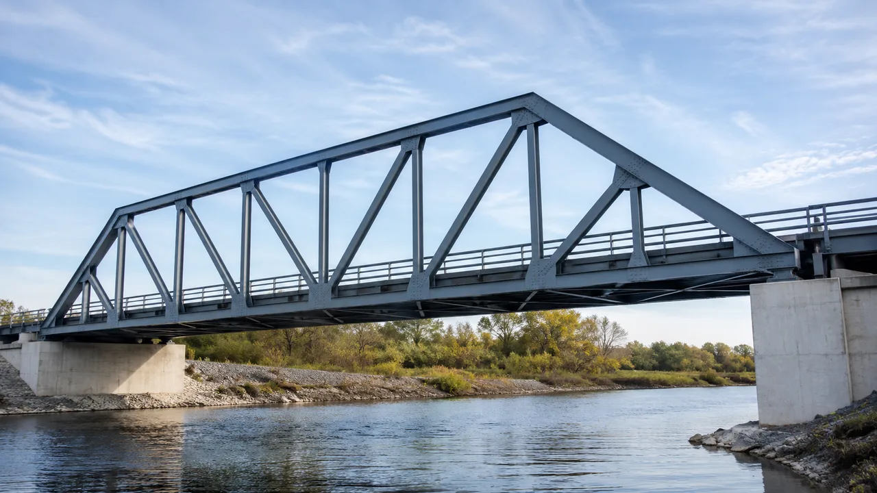
Bridge Applications
Historically, Howe trusses were widely used in bridge construction, especially in covered bridges and early timber-and-metal bridge systems. The arrangement was practical because timber could be used for compression diagonals and iron rods could be used for vertical tension members. This combination made sense with the materials and construction methods available at the time.
In modern bridge projects, the same general geometry may still be useful, but the design process is much more detailed. Engineers must consider pedestrian or vehicle loads, deck weight, wind, vibration, support conditions, fatigue, corrosion protection, inspection access, and code requirements. A bridge truss must also be detailed for long-term maintenance because many connections and exposed members may be affected by weather over time.
For pedestrian bridges, service bridges, pipe bridges, or industrial access bridges, a Howe-type arrangement can provide a clear and readable structural system. However, it still needs proper lateral bracing, connection design, and erection planning.
Roof Truss Applications
Howe-type truss arrangements can also be used in roof systems. In a roof, the truss may support purlins, roof panels, insulation, suspended lighting, ducts, ceiling systems, and maintenance loads. Depending on the location, it may also need to resist wind uplift, rain load, snow load, or seismic effects.
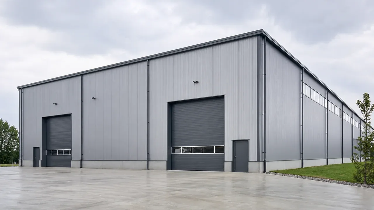
Roof trusses are common in warehouses, workshops, agricultural buildings, industrial sheds, and other structures that need wide interior space. A truss system can reduce the need for intermediate columns and create a more open working area below. This is useful when the building needs room for storage racks, production lines, vehicles, cranes, or equipment.
For roof use, the truss must be coordinated with the rest of the steel building system. Purlins, roof bracing, end frames, sidewall columns, gutters, cladding, insulation, and installation sequence all affect how the roof performs. A strong truss alone is not enough if the surrounding system is poorly planned.
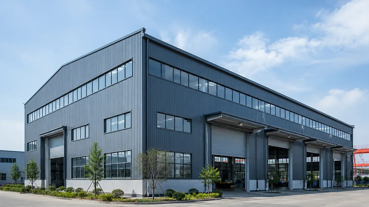
Industrial and Steel Building Use
In industrial steel buildings, Howe-type truss logic may appear in roof structures, conveyor galleries, pipe racks, equipment platforms, access bridges, and service structures. These projects often need efficient load transfer, open space, and durable steel framing.
A factory building may use truss systems to support large roof spans above production areas. A warehouse may need long-span roof members to keep the interior open for storage and logistics. A conveyor structure may use trussed side frames to carry loads between support towers. A pipe rack may require a stable frame that supports vertical loads, lateral loads, and thermal movement from piping systems.
For these applications, the design should reflect real industrial use. Equipment loads may be concentrated, moving, vibrating, or eccentric. Maintenance access may create additional live loads. Outdoor structures may require stronger corrosion protection. The truss should be designed as part of the full steel structure, not treated as an isolated component.
Advantages of a Howe Truss
One advantage of a Howe truss is its clear triangulated geometry. The repeated panel arrangement makes it easy to understand how loads move through the structure. This can help engineers, fabricators, inspectors, and field crews read the structural system more clearly.
Another advantage is material efficiency when the truss is properly designed. Instead of using one heavy beam to cross a span, the truss distributes force through multiple members. This can reduce self-weight and make the structure more practical for medium or long spans. In steel building projects, lower self-weight can also support easier transportation and lifting.
The repeated geometry can also support fabrication planning. Similar panel dimensions, repeated member types, and standardized connection details can make shop drawings clearer and reduce confusion during production. When cutting, drilling, welding, blasting, painting, labeling, and packing are organized properly, a truss system can move through the fabrication process efficiently.
For inspection and maintenance, the open web form is also useful. Members and connections are visible, which can make it easier to identify corrosion, deformation, coating damage, loose bolts, or other issues. This is especially important for bridges, outdoor industrial structures, and exposed steel systems.
Limitations and Design Challenges
A Howe truss also has limitations. The most important design challenge is the compression behavior of the diagonal members. Since the diagonals commonly work in compression under typical gravity loading, they must be checked carefully for buckling. A long, slender diagonal may fail by instability even if the steel section appears strong enough in simple stress calculations.
Connection design is another major challenge. Trusses contain many joints, and each joint must transfer force between members safely. Gusset plates, bolts, welds, splice plates, hole positions, edge distances, and fabrication tolerances all affect performance. If connection details are weak or difficult to assemble, the strength of the whole truss can be compromised.
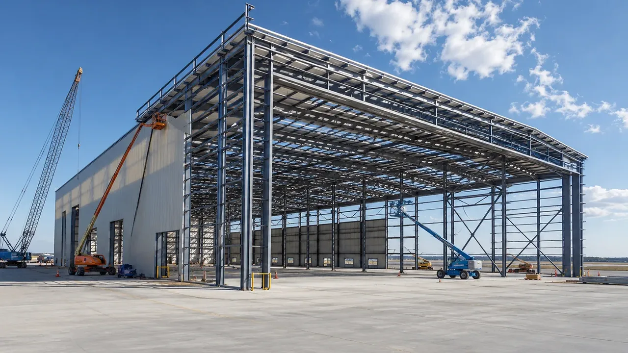
Lateral stability must also be considered. A truss may be strong in its own vertical plane but unstable out of plane if it is not properly braced. This is especially important during lifting and erection, when the full roof, deck, or bracing system may not yet be installed. Temporary bracing may be necessary to keep the structure stable before the permanent system is complete.
Transportation and erection can also influence the design. Large trusses may need to be split into transportable sections. These sections must then be connected on site with accurate alignment. If the fabrication plan ignores transport size, lifting points, site access, or assembly sequence, installation can become slower, more expensive, and less safe.
Key Design Factors Before Choosing a Howe Truss
Before choosing a Howe truss, the project team should review the full structural and construction context. The truss type should match the span, loads, material, fabrication capacity, transport route, installation method, and long-term maintenance plan.
Span and Panel Layout
Span length has a major effect on truss design. Longer spans usually require deeper trusses, stronger chords, more careful deflection control, and stronger lateral bracing. A short-span truss may be simple to fabricate, while a long-span truss may require segmental fabrication, field splicing, and special lifting planning.
Panel layout also matters. If panels are too long, member forces and deflection may increase. If panels are too short, the truss may require too many members and connections. A good design balances structural efficiency with fabrication simplicity.
Loading Conditions
The load pattern should be studied carefully. Roof trusses may carry dead load, wind uplift, snow, rain, suspended services, and maintenance loads. Bridge trusses may carry deck loads, pedestrian loads, vehicle loads, lateral loads, and dynamic effects. Industrial trusses may carry conveyors, pipes, equipment, platforms, or access walkways.
Loads should be introduced into the truss at planned panel points whenever possible. If loads are applied between panel points, local bending may occur in members that were intended mainly for axial force. This can increase member size and create additional detailing requirements.
Member Sizing and Buckling Control
Member sizing should follow actual force demand. The top chord, bottom chord, vertical members, and diagonal members may all carry different forces. Compression members require special attention because they can fail by buckling. Their unsupported length, section shape, slenderness, end condition, and bracing arrangement must be checked.
For a Howe arrangement, compression diagonals are especially important. Designers should avoid assuming that a diagonal is safe just because the axial force seems moderate. If the member is long or slender, stability may control the design.
Connection Design
Connection design is critical in any truss. A truss is only as reliable as its joints. Gusset plates, bolts, welds, splice plates, and member ends must be detailed so that forces can transfer clearly from one member to another.
Accurate fabrication helps reduce field problems. CNC drilling, proper fit-up control, clear member marking, and well-prepared shop drawings can reduce the risk of hole misalignment and site rework. Good connection design should also consider inspection access and coating maintenance, especially for outdoor or industrial structures.
Bracing and Installation Sequence
A truss must be stable during both final service and construction. Permanent bracing helps control out-of-plane movement, while temporary bracing may be required during erection. This is important because a truss can be vulnerable before all connected systems are installed.
The installation sequence should be planned before fabrication is complete. Lifting points, temporary supports, field splice locations, bolt access, crane reach, and working platform requirements all influence whether the truss can be installed safely and efficiently.
Common Mistakes in Howe Truss Projects
| Mistake | Why It Matters | Better Project Approach |
|---|---|---|
| Choosing a Howe truss only because it is familiar | A familiar truss form may not match the actual span, load path, material choice, or construction method. | Compare truss types based on engineering demand, fabrication capacity, erection plan, and long-term maintenance. |
| Ignoring compression buckling in diagonal members | Howe diagonals commonly work in compression, and slender compression members can fail by buckling. | Check member slenderness, unsupported length, bracing condition, and section shape during design. |
| Underestimating connection design | Weak gusset plates, poor bolt layouts, bad weld details, or misaligned holes can reduce the capacity of the whole system. | Design connections carefully and coordinate shop drawings, CNC drilling, welding, and field assembly requirements. |
| Forgetting lateral bracing | A truss may look stable in elevation but still twist or move out of plane without proper bracing. | Plan permanent bracing and temporary erection bracing as part of the complete structural system. |
| Planning fabrication without considering transport size | Large truss sections may be difficult or impossible to move if transport limits are ignored. | Check transport route, section length, field splice locations, lifting weight, and site access early. |
| Treating installation sequence as an afterthought | The truss may be unstable during lifting before the complete system is connected. | Plan lifting points, temporary supports, erection bracing, crane access, and assembly sequence before site work begins. |
| Using weak corrosion protection in exposed environments | Outdoor and industrial structures can suffer from moisture, chemicals, dust, and coating damage over time. | Select suitable painting, galvanizing, drainage, inspection access, and maintenance planning for the environment. |
When Should You Choose a Howe Truss?
A Howe truss can be a good option when its geometry matches the project load path and when compression members can be properly sized and braced. It may be useful for roofs, bridge-related structures, industrial service frames, and steel building systems where repeated triangulated panels provide a practical structural solution.
It may also be suitable when the project benefits from clear panel repetition. Repeated geometry can help fabrication, shop drawing organization, member marking, and field assembly. If the project team can standardize member lengths and connection details, the truss may become easier to produce and install.
However, another truss type may be better if the project prefers tension diagonals, if compression buckling becomes difficult to control, if architectural depth is limited, or if transportation and erection constraints favor a different system. The choice should come from structural analysis and project planning, not from visual preference alone.
Conclusion
The Howe truss is a classic truss form with a clear structural logic. Its diagonal members and vertical members create a load path that differs from Pratt and Warren systems, making it useful for understanding how trusses respond to gravity loads, member forces, and support reactions.
In bridges, roof systems, industrial structures, and steel building applications, this truss type can be practical when the design matches the span, loading pattern, fabrication method, bracing system, and installation plan. Its repeated geometry can support efficient production, but its compression diagonals and many connections require careful engineering.
A successful truss project depends on more than choosing a truss shape. Member sizing, connection design, lateral bracing, corrosion protection, transport planning, and erection sequence all need to work together. When these factors are properly coordinated, a Howe truss can provide a durable, efficient, and understandable structural solution.