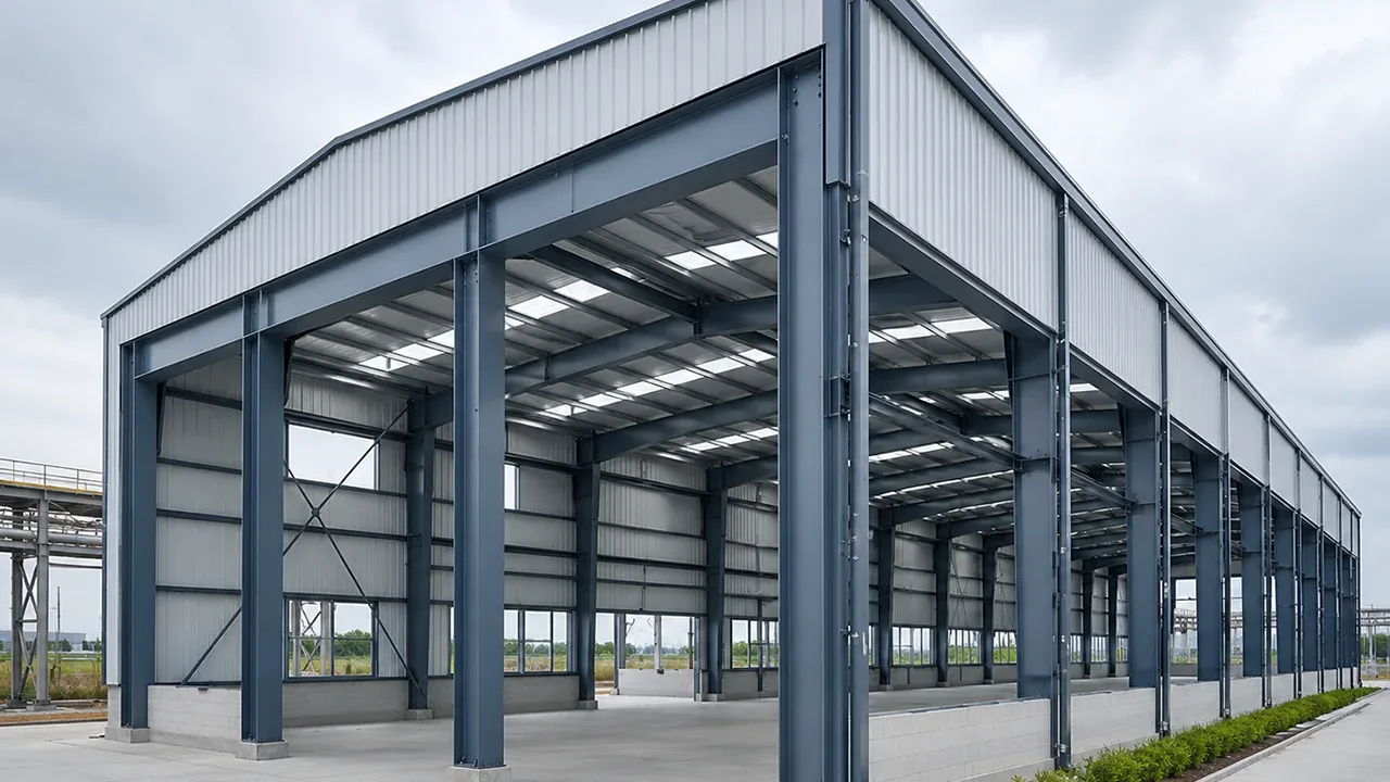
Prefabricated steel buildings are valued for fast erection, accurate fabrication, reduced site labor, and predictable assembly. In warehouses, factories, logistics centers, industrial plants, and modular buildings, steel members can be cut, drilled, welded, marked, and trial-coordinated before they arrive on site. This gives project teams better control over quality and schedule. However, when a building must perform under earthquake forces, speed and dimensional accuracy alone are not enough.
Prefab seismic detailing is the process of designing and coordinating prefabricated steel components so they can transfer seismic forces safely through the structure. It is not only about making members stronger. It is about connection behavior, ductility, deformation capacity, load path continuity, installation tolerance, and the ability of the building to respond to repeated movement during an earthquake.
Earthquakes do not apply force in the same simple way as ordinary gravity loads. A building may support its vertical loads well under normal service conditions, but still perform poorly if the seismic load path is incomplete or if critical connections are too brittle. In prefabricated steel construction, this challenge becomes more important because many details are already locked in before the members reach the site. Bolt holes, splice plates, brace geometry, gusset dimensions, base plates, and modular interfaces must be planned correctly before fabrication begins.
That is why seismic performance in prefabricated steel buildings depends on coordination from engineering to fabrication to erection. If the design team, manufacturer, and site crew do not follow the same detailing strategy, small errors can become structural weaknesses. A misplaced anchor bolt, an over-modified field connection, an incomplete diaphragm path, or a poorly aligned brace can interrupt how lateral load moves through the building.
Why Seismic Detailing Matters in Prefabricated Steel Construction
Earthquake forces are different from ordinary gravity loads
Gravity loads usually act downward. Dead loads, live loads, equipment loads, and stored goods generally move through beams, columns, base plates, and foundations in a relatively predictable vertical path. Seismic forces are different. Earthquake movement creates horizontal acceleration, vibration, force reversal, cyclic loading, and dynamic stress. The building must resist not only weight, but also repeated movement from side to side.
This is where lateral load becomes central to seismic detailing. Lateral force must move from the roof or floor diaphragm into collectors, frames, braces, columns, base plates, anchor bolts, and foundations. If any part of this path is weak, discontinuous, or poorly connected, the building may not behave as intended during seismic movement.
Seismic detailing therefore focuses on how forces are transferred and dissipated. Strong steel members alone do not guarantee safe seismic behavior. A heavy column can still perform poorly if its base plate is not properly detailed. A strong brace can fail if its gusset plate does not allow the expected movement. A well-fabricated beam can still create problems if the beam-to-column connection lacks ductility.
Prefabrication improves accuracy but reduces field flexibility
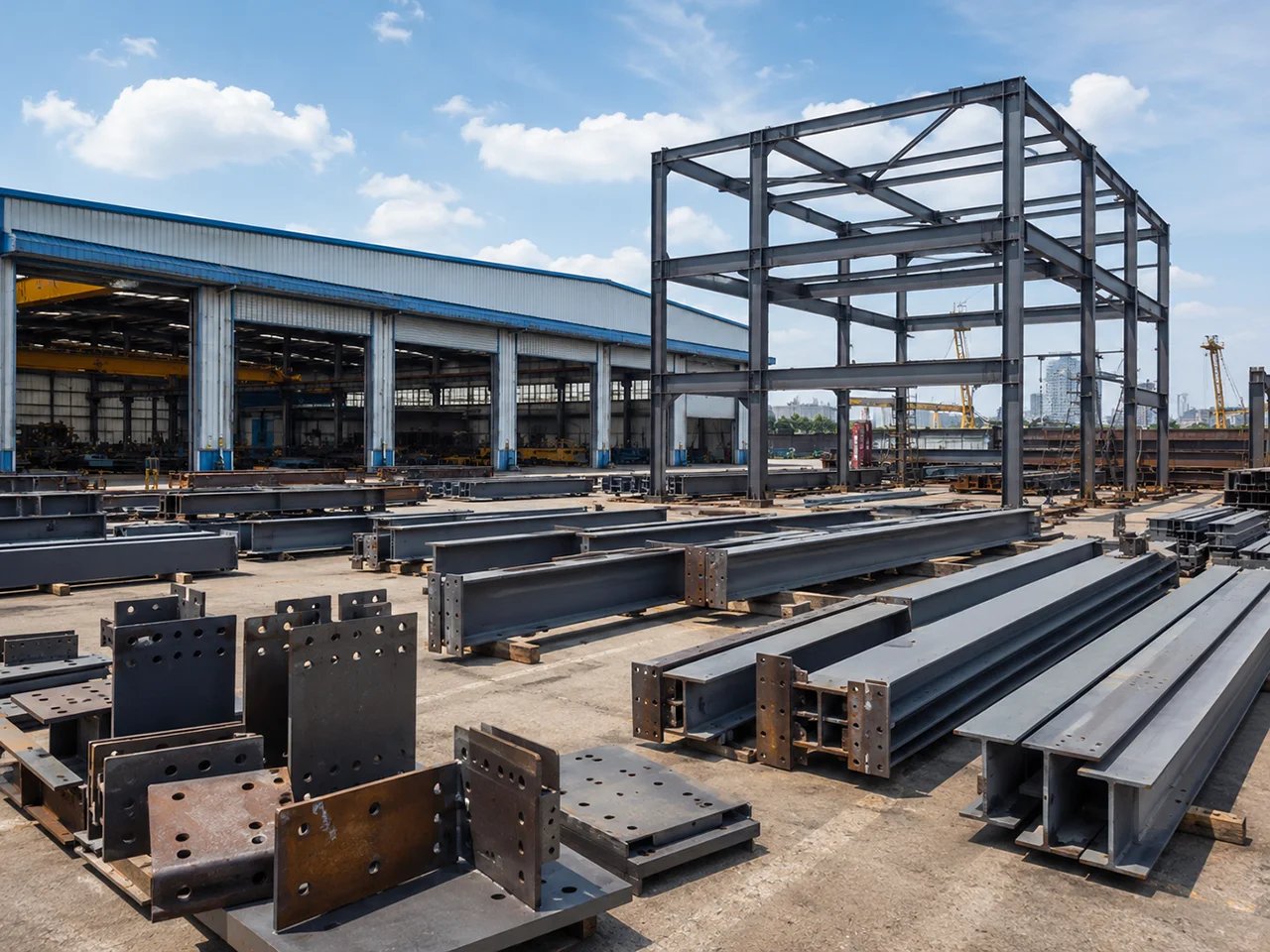
One advantage of prefabricated steel construction is that fabrication happens in a controlled environment. Holes can be drilled accurately, welds can be inspected before shipment, members can be marked, and connection plates can be prepared according to approved shop drawings. This improves quality compared with uncontrolled field adjustment.
However, that same accuracy also means the design must be correct early. In conventional site-built work, some minor changes may be absorbed through field welding, drilling, cutting, or adjustment. In a prefabricated system, excessive field correction can damage the intended seismic strategy. A connection that was designed to transfer force in a specific way should not be casually modified on site to solve an alignment issue.
This is one of the main reasons prefab seismic detailing must be reviewed before production. The structural design, shop drawings, fabrication sequence, erection method, and inspection requirements need to match each other. If seismic-critical members are fabricated before connection details are finalized, the project may face rework, delays, or compromised performance.
Connection behavior controls seismic performance
Connections are often the most important part of seismic detailing. In an earthquake, beams, columns, braces, splice plates, anchor bolts, gusset plates, and weld zones must work together. They must transfer force while still allowing the structure to deform in a controlled way.
A common mistake is thinking that stronger and more rigid always means better. In seismic design, ductility matters. The structure must have the ability to absorb and dissipate energy without sudden brittle failure. Certain areas may need to yield in a predictable way, while other areas must remain stable enough to preserve the overall load path.
For prefabricated steel buildings, this means connection design must consider not only strength, but also constructability. Bolt access, weld quality, plate thickness, installation tolerance, erection sequence, and inspection access all influence whether the designed connection can actually be built correctly.
Main Seismic Detailing Challenges in Prefabricated Steel Buildings
Maintaining a continuous lateral load path
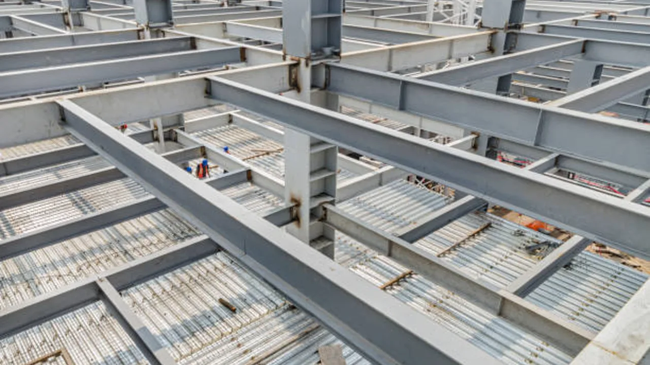
A continuous lateral load path is one of the most important requirements in seismic design. Earthquake forces must be collected and transferred through the building without interruption. In a steel building, this path may include roof decking, purlins, diaphragm connections, collectors, braced bays, moment frames, columns, base plates, anchor bolts, and foundations.
In prefabricated steel systems, the load path can become more complicated because the building is often divided into transportable members, repeated bays, modular sections, or preassembled components. Every division line introduces an interface. Each interface must be detailed so that seismic forces continue through the structure rather than stopping at a weak joint.
For example, if roof diaphragm forces are supposed to move into a braced frame, the connection between roof members, collectors, and the bracing bay must be clearly detailed. If a modular frame line is interrupted by a transport splice, that splice must be designed to transfer the required seismic force. If base plates are placed on inaccurate foundations, the force path into the foundation may not work as expected.
Designing connections for movement and force reversal
Earthquake forces can reverse direction many times during a single event. A brace may be pulled in tension and then pushed into compression. A beam-column connection may experience repeated rotation. Anchor bolts may see alternating tension and shear demand. This makes seismic connection behavior more demanding than ordinary static loading.
Bolted connections must be detailed so they do not loosen, slip unexpectedly, or concentrate stress in the wrong area. Welded connections must be designed and inspected with enough care to avoid brittle failure. Gusset plates must provide force transfer while allowing the expected brace behavior. Splice locations must be selected so they do not create weak points in high-demand zones.
In prefab seismic detailing, these decisions should be reflected clearly in shop drawings. It is not enough for the engineering design to show a general connection concept. The fabricator needs precise plate sizes, hole patterns, weld symbols, stiffener locations, bolt specifications, and erection notes. The site team also needs to know which connections are seismic-critical and cannot be modified without engineering approval.
Controlling tolerance between factory fabrication and site erection
Prefabrication depends on accurate fit-up. But seismic detailing also depends on accurate alignment. A member that is slightly out of position may still look acceptable visually, but it can change how forces flow through the structure. This is especially important for bracing systems, moment frames, base plates, and module-to-module joints.
Common tolerance issues include bolt-hole misalignment, uneven foundation elevations, column plumbness variation, base plate gaps, cumulative bay spacing errors, and module interface mismatch. These issues may appear small individually, but they can become significant when repeated across a long building.
When field crews try to solve tolerance problems by enlarging holes, forcing members into position, cutting plates, or adding unapproved welds, the intended seismic behavior may be affected. This is why tolerance planning should be part of seismic coordination, not treated as a separate erection issue.
Avoiding weak points at module-to-module interfaces
Prefabricated buildings often use repeated frames, modular units, or preassembled steel sections. This improves speed, but it also creates repeated interfaces. Every repeated interface must perform consistently. If one module joint is detailed correctly but another is installed poorly, the building may have uneven stiffness or local weak points.
Module-to-module joints may need to transfer gravity loads, diaphragm forces, brace reactions, frame continuity, and service loads at the same time. If the interface is only designed for basic fit-up, it may not perform well under seismic demand. The connection must be reviewed for force transfer, deformation capacity, access for bolting, inspection visibility, and compatibility with surrounding cladding or floor systems.
This is one reason why repeated prefab connections should not be treated casually. The more often a connection is repeated, the more important its detailing becomes. A small weakness repeated across many bays can become a major seismic performance issue.
Critical Areas That Need Seismic Detailing Review
Beam-to-column connections
Beam-to-column connections are often central to seismic response, especially in moment-resisting frames. These joints may need to provide rotation capacity, transfer bending forces, resist shear, and maintain stability during cyclic loading. Poorly detailed beam-column joints can create brittle failure, local distortion, or unexpected stress concentration.
Seismic review should consider weld access, flange continuity, stiffener requirements, bolt arrangement, panel zone behavior, plate thickness, and erection sequence. In prefabricated systems, the fabricator must understand which welds or plates are seismic-critical, because these details may require additional inspection or controlled fabrication procedures.
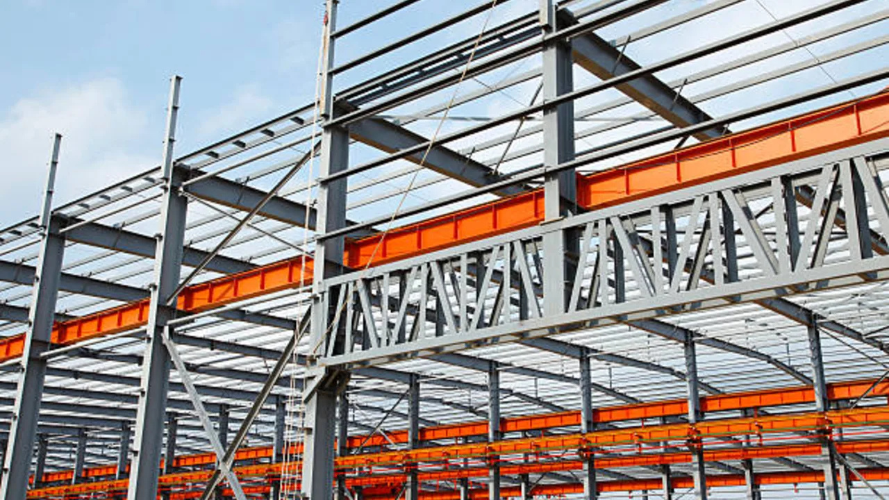
Bracing systems and gusset plates
Bracing systems are commonly used to resist lateral load in steel buildings. Concentric bracing, eccentric bracing, and other braced configurations can provide efficient seismic resistance when properly detailed. However, bracing systems are highly sensitive to geometry and connection behavior.
Gusset plates must be sized and positioned to transfer force while allowing the expected brace deformation. Brace buckling, tension yielding, compression behavior, bolt layout, and clearance around the gusset all matter. If a brace arrives on site with incorrect hole alignment or if the gusset plate does not match the intended geometry, the system may not perform as designed.
Base plates and anchor bolts
Base plates and anchor bolts transfer seismic forces from the steel frame into the foundation. This area is critical because even a well-detailed steel frame depends on accurate foundation coordination. Anchor bolt layout, edge distances, embedment, grout quality, leveling plates, and base plate thickness all influence the connection between steel and concrete.
Problems at the base can affect the entire building. Misplaced anchor bolts may lead to field slotting or forced fit-up. Uneven grout may reduce bearing performance. Insufficient edge distance may reduce anchor capacity. Because prefabricated steel members arrive with fixed base plate holes, foundation accuracy must be confirmed before erection begins.
Diaphragm and roof system connections
Roof systems should not be treated as secondary only. In many steel buildings, roof decking, purlins, collectors, drag struts, and diaphragm edge connections play a major role in transferring seismic forces into the lateral force-resisting system.
If diaphragm connections are weak or discontinuous, the building may not deliver force to the frames or braces as intended. This can be especially risky in wide-span industrial buildings where the roof system covers a large area. Proper detailing must show how diaphragm forces are collected, transferred, and anchored into the main seismic system.
| Detail Area | Common Risk | Why It Matters | Practical Control Measure |
|---|---|---|---|
| Beam-column joints | Insufficient ductility or poor weld access | These joints often control frame rotation and seismic response. | Review stiffeners, weld details, bolt layout, and inspection access before fabrication. |
| Brace-to-gusset connections | Incorrect geometry or restricted brace movement | Bracing systems must transfer force while allowing expected deformation. | Check gusset clearance, bolt layout, brace alignment, and shop drawing accuracy. |
| Base plates and anchors | Misplaced anchors or inadequate grout support | Seismic forces must transfer safely into the foundation. | Verify anchor templates, foundation elevations, embedment, and base plate fit-up before erection. |
| Module-to-module joints | Discontinuous force transfer between prefabricated sections | Repeated joints can create repeated weak points if not detailed consistently. | Standardize interface details and inspect every repeated connection type. |
| Roof diaphragm connections | Weak collector or diaphragm edge detailing | Roof systems often transfer lateral forces into braced frames or moment frames. | Coordinate decking, purlins, collectors, drag struts, and frame connections. |
| Field bolted splice zones | Improper bolt tightening or unapproved hole modification | Splices must maintain the intended seismic load path during cyclic movement. | Use clear bolt specifications, installation records, and inspection checkpoints. |
Factory Fabrication Issues That Affect Seismic Performance
Weld quality and inspection planning
Factory fabrication can improve seismic quality when welding is controlled, inspected, and documented properly. Welded zones in seismic-critical members may need specific procedures, qualified welders, proper access, controlled heat input, and inspection records. These requirements should be planned before production begins, not discovered after members are already fabricated.
Weld quality is especially important around beam-to-column connections, brace end connections, stiffener plates, splice plates, base plate assemblies, and transfer frames. A weld that looks acceptable for ordinary service may still be unsuitable if it lacks the toughness, continuity, or inspection level required for seismic behavior.
Good fabrication planning should define the welding procedure specification, inspection method, hold points, repair process, and documentation requirements. If a weld is part of the seismic force-resisting system, it should be treated as a critical detail, not as a routine shop weld.
Hole accuracy and bolted joint preparation
Bolted connections are widely used in prefabricated steel buildings because they support fast site assembly. However, seismic performance depends on more than simply aligning bolt holes. Hole size, bolt grade, washer type, plate thickness, slip-critical requirements, tightening method, and inspection discipline all influence connection reliability.
If holes are inaccurately drilled or enlarged in the field without approval, the connection may not behave as intended. Oversized or slotted holes can be useful when designed properly, but they should not be created casually during erection to solve a fit-up issue.
For prefab seismic detailing, bolted joint requirements must be clear in both engineering drawings and shop drawings. Fabricators need to know which connections are standard, which are slip-critical, which require pretensioning, and which areas cannot be altered on site.
Member marking and assembly sequencing
Prefabricated steel relies heavily on correct member marking. Each beam, column, brace, plate, and module must arrive on site with clear identification so the erection crew can install it in the correct location and orientation. This is especially important in seismic zones because connection direction, brace orientation, and splice position may affect force transfer.
If members are mislabeled or installed out of sequence, the site team may force connections into place or make unapproved modifications. These corrections may appear minor, but they can reduce the integrity of seismic detailing.
A good marking system should link fabrication drawings, packing lists, erection drawings, and inspection records. This helps the site team assemble the structure according to the intended seismic design rather than relying on improvisation during installation.
Site Installation Challenges in Seismic Detailing
Foundation accuracy and anchor bolt placement
Foundation accuracy is one of the most common site challenges in prefabricated steel construction. Steel members are fabricated with fixed dimensions, while anchor bolts and concrete foundations are constructed on site. If these two systems do not match, erection problems can appear immediately.
Anchor bolts must be located correctly in plan and elevation. Base plates must sit properly on grout or leveling systems. Foundation elevations must support column alignment. When anchor bolts are misplaced, the site team may be tempted to enlarge holes, shift base plates, cut washers, or modify the steel. These actions can affect the seismic connection between the frame and foundation.
Before steel erection begins, anchor bolt templates, foundation surveys, base elevations, and grout requirements should be checked carefully. This step helps protect the designed load path and prevents field corrections that may weaken seismic performance.
Field welding and touch-up around seismic zones
Field welding may be necessary in some prefabricated projects, but it must be controlled carefully in seismic-critical zones. Welding in the field is usually more difficult than welding in a factory because weather, access, lighting, working position, and inspection conditions are less predictable.
Any field weld near beam-column joints, brace connections, base plates, or splice zones should follow approved procedures. Cutting, grinding, drilling, or welding should not be performed casually just to solve a fit-up issue. If the connection is part of the seismic system, engineering approval should be required before modification.
Touch-up work also matters. If protective coatings, galvanizing, or fire protection materials are damaged during field work, repairs should be coordinated without hiding critical connection defects. The goal is not only to restore surface protection, but also to preserve the intended structural behavior.
Bolt tightening and inspection discipline
Seismic detailing depends on execution. A connection may be designed correctly, fabricated accurately, and still perform poorly if bolts are not installed properly. Bolt tightening requirements should be clearly defined and inspected during erection.
Some connections may require snug-tight installation, while others may require pretensioning or slip-critical preparation. The installation crew must understand the difference. Torque control, turn-of-nut procedures, calibrated tools, inspection marks, and installation records may all be required depending on the connection type.
For field bolted splice zones, inspection should occur before the connection becomes hidden by cladding, decking, fireproofing, or other building systems. Once covered, it becomes much harder to verify whether the connection was installed correctly.
How Engineers Manage Lateral Load in Prefabricated Steel Buildings
Defining the seismic force-resisting system
The seismic force-resisting system must be defined early. This system may include moment frames, braced frames, shear walls, diaphragm systems, collectors, or hybrid arrangements depending on the project. Once the system is selected, every related detail must support that choice.
In prefabricated steel buildings, this decision affects fabrication splits, connection design, member marking, transport sections, erection sequence, and inspection planning. A brace frame, for example, may require different gusset detailing and bolt inspection than a moment frame. A diaphragm-based system may require careful coordination between roof decking, purlins, collectors, and frame lines.
If the seismic system is not clearly communicated to the fabricator and installer, critical details may be treated as ordinary connections. That can weaken how the building resists lateral load during an earthquake.
Coordinating frame action with diaphragms and collectors
Earthquake forces do not automatically reach the strongest part of the building. They must be collected and transferred through a complete path. Diaphragms, collectors, drag struts, purlin lines, roof bracing, and frame connections all help move force into the main seismic system.
In wide industrial buildings, the roof system can play a major role in this process. If diaphragm edges are weak, collector members are missing, or roof connections are treated as secondary details, seismic force transfer may become incomplete.
Coordination between the roof system and frame system is therefore essential. Engineers should verify that the diaphragm can collect force, collectors can transfer it, and the main frames or braces can deliver it safely into the foundation.
Allowing ductility without losing stability
Seismic design is not about making every connection as rigid as possible. A building needs enough strength to resist collapse, but it also needs enough ductility to absorb earthquake energy. Controlled deformation can protect the structure from sudden brittle failure.
This balance is delicate in prefabricated systems. Factory-made components are accurate, but they must still allow the intended seismic behavior. Connections, braces, plates, and welds should be detailed so the building can deform in predictable ways while maintaining overall stability.
Good prefab seismic detailing defines where yielding may occur, where stability must be preserved, and how force moves through the building after deformation begins. Without this clarity, the structure may appear strong but behave unpredictably under seismic demand.
Design Coordination Before Fabrication
Aligning structural drawings with fabrication drawings
Structural drawings and fabrication drawings must tell the same story. If the engineering drawings show seismic-critical details but the shop drawings simplify or reinterpret them incorrectly, the final steel may not match the intended design.
Important items include plate sizes, stiffener locations, weld symbols, bolt grades, hole patterns, brace orientation, splice details, base plate requirements, and inspection notes. Any mismatch should be resolved before production begins.
Shop drawing review should not focus only on dimensions and quantities. It should also verify whether seismic detailing has been carried through accurately from design intent to fabrication reality.
Reviewing prefab module interfaces before production
Module boundaries, transport splits, and field splice zones must be reviewed carefully before production. These interfaces are often where structural continuity becomes most vulnerable. A connection may need to transfer gravity load, diaphragm force, brace reaction, and frame continuity at the same time.
For a prefabricated steel structure building, these interfaces should be treated as part of the main structural system rather than simple assembly joints. If the interface is repeated throughout the building, the risk is multiplied. A weak or unclear detail repeated many times can become a serious seismic performance issue.
The project team should confirm how modules connect, how forces cross module boundaries, where field bolts are installed, which areas require inspection, and what modifications are prohibited during erection.
Using BIM and 3D coordination to prevent conflicts
BIM and 3D coordination can help identify seismic detailing conflicts before fabrication. Digital models can show brace geometry, connection access, base plate locations, bolt clearances, roof diaphragm paths, and module interfaces more clearly than 2D drawings alone.
For complex prefabricated buildings, digital coordination can reduce errors between structural design, fabrication, foundation work, cladding, MEP systems, and erection planning. It also helps installation teams understand which areas are critical before the steel arrives on site.
BIM does not replace engineering judgment, but it can make coordination more visible. When used properly, it helps prevent clashes, tolerance conflicts, and unclear connection responsibilities.
Common Mistakes in Prefab Seismic Detailing
Treating seismic connections like ordinary connections
One common mistake is treating seismic-critical connections as if they are ordinary framing joints. In reality, these connections may need special detailing, controlled fabrication, specific bolt installation, additional weld inspection, or stricter field modification rules.
If the site team does not know which connections are seismic-critical, they may unintentionally damage performance. Clear marking, drawing notes, and inspection checkpoints help prevent this problem.
Ignoring cumulative tolerance across repeated modules
Small dimensional errors can accumulate across repeated prefab modules. A slight spacing issue in one bay may not appear serious, but across many bays it can shift brace alignment, diaphragm edges, or frame geometry.
Cumulative tolerance should be reviewed during design and erection planning. Repeated module interfaces need consistent inspection because the same small problem can appear many times across the building.
Modifying connection details in the field without engineering review
Field modification is one of the biggest risks in seismic detailing. Enlarging bolt holes, cutting plates, grinding welds, adding welds, or forcing members into position may solve a short-term installation issue while creating a long-term structural problem.
Any modification to seismic-critical members should require engineering review. This protects the intended load path and ensures that the building’s seismic behavior is not changed without proper analysis.
Focusing only on primary frames and forgetting secondary load paths
Primary frames and braces are important, but they are not the only parts of the seismic system. Purlins, girts, collectors, cladding supports, roof decking, diaphragm connections, and edge members can all help transfer seismic forces.
If secondary load paths are ignored, the building may not deliver force to the main seismic system correctly. This is especially important in industrial buildings with large roof areas and long structural grids.
Quality Control Checklist for Seismic Detailing
Before fabrication
- Confirm project seismic requirements and applicable design assumptions.
- Identify the seismic force-resisting system clearly.
- Review the complete lateral load path from diaphragm to foundation.
- Confirm beam-column, brace, base plate, and splice connection details.
- Check member orientation, marking system, and erection sequence.
- Define welding, bolting, and inspection requirements before production.
During fabrication
- Verify weld quality and required inspection records.
- Check bolt-hole locations, plate dimensions, and brace geometry.
- Confirm stiffeners, gusset plates, and splice plates match approved shop drawings.
- Inspect seismic-critical members before coating or shipment.
- Record production data for traceability.
During erection
- Verify anchor bolt location and foundation elevation before setting steel.
- Check column plumbness, frame alignment, and base plate fit-up.
- Confirm bolt tightening method and inspection records.
- Inspect field welds and field splice zones.
- Review diaphragm, collector, brace, and module interface connections before concealment.
Long-Term Performance and Maintenance
Post-installation inspection after major seismic events
After a significant earthquake, prefabricated steel buildings should be inspected before returning fully to normal operation. Even if the building appears stable, hidden connection damage may exist. Inspection should focus on visible deformation, cracked welds, loosened bolts, brace buckling, base plate movement, damaged cladding supports, and foundation distress.
Buildings with industrial equipment, overhead cranes, mezzanines, or heavy storage systems may require additional review because operational loads can interact with seismic damage. Any suspected structural damage should be evaluated by qualified engineers before repairs are performed.
Maintaining connection integrity over time
Seismic performance is not only a design-stage concern. Over time, corrosion, impact damage, unauthorized modification, bolt loosening, coating damage, equipment changes, or added service penetrations can affect the intended load path.
Owners should maintain inspection records and review critical connections periodically. If new equipment, platforms, openings, or service systems are added, the effect on seismic detailing should be checked. A building that was properly detailed at construction can still lose performance if later modifications interrupt key structural paths.
Conclusion
Prefabricated steel buildings can perform well in seismic regions when detailing is planned early and executed carefully. The advantages of factory fabrication, accurate member production, and fast erection are valuable, but they must be matched with connection discipline, load path continuity, ductility planning, and field inspection.
Effective prefab seismic detailing requires more than strong steel members. It requires a complete understanding of how earthquake forces move through the building, how connections deform, how fabrication tolerances affect erection, and how the site team preserves the design intent during installation.
When engineers, manufacturers, and erection crews coordinate from the beginning, the building is more likely to maintain a reliable lateral load path from roof diaphragm to foundation. That coordination is what turns prefabricated steel from a fast construction method into a dependable structural system for seismic environments.