Beam-to-column moment connections transfer substantial tension and compression forces through the beam flanges into the column. When the column flange or web cannot resist these concentrated forces alone, continuity plates or other stiffening elements may be required to reinforce the connection region. Providing a stiffener, however, does not automatically guarantee adequate performance. A plate may have sufficient area to resist yielding while still being vulnerable to instability under compression.
For this reason, stiffener buckling checks should be considered together with strength, load transfer, weld design, and the behavior of the surrounding column components. Plate thickness, unsupported dimensions, boundary restraint, fabrication tolerances, and the actual compressive force carried by the stiffener can all influence whether the intended load path remains stable.
Why Stiffener Buckling Matters in Moment Connections
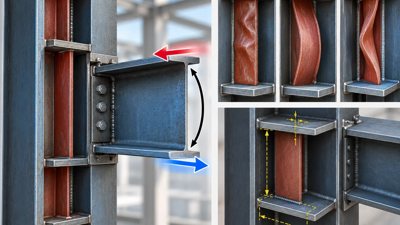
A moment transferred from a beam into a column produces opposing forces at the beam flanges. One flange typically introduces tension while the other introduces compression, with the direction reversing when the applied moment reverses. These concentrated forces act close to the column flange and can create significant localized demands in the column web, flange, continuity plates, and welds.
On the compression side, a relatively thin stiffener may become unstable before developing the resistance assumed in the connection design. Local plate buckling can distort part of the stiffener, while inadequate restraint may allow a larger portion of the plate to move out of plane. Either condition can reduce stiffness and alter how force is distributed through the joint.
This is why yielding and buckling should not be treated as the same limit state. A plate can remain below its material yield strength while its geometry makes it susceptible to instability.
How Moment Forces Reach the Stiffeners
Before performing detailed stiffener buckling checks, the designer needs a clear understanding of the connection load path. Beam flange forces must pass through the connection components, into the column flange, and then into the column web, continuity plates, or other reinforcement before being distributed into the column section.
Understanding how moment loads beam stiffeners is especially important because the force assigned to a stiffener should come from the actual connection analysis rather than from an isolated assumption about beam flange force.
In some connections, the existing column flange and web can resist a substantial portion of the concentrated load. In others, reinforcement must carry a larger share. One-sided and two-sided beam connections can also produce different demand patterns, particularly when the moments on opposite sides of the column are unequal.
The design force used for a stiffener therefore depends on connection geometry, column dimensions, material properties, beam flange force, and the limit states that govern the unreinforced column.
Where Buckling Can Develop in a Stiffener
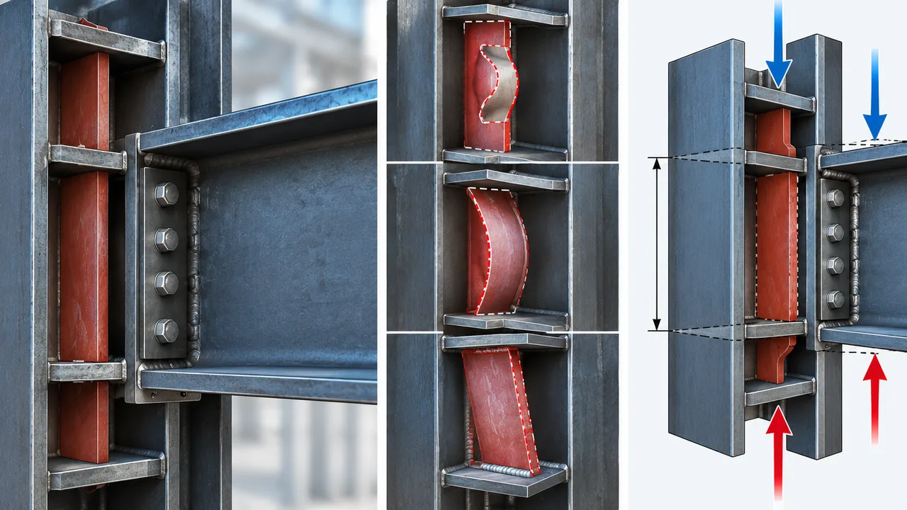
Local Plate Buckling
Local buckling occurs when an individual portion of the stiffener plate becomes unstable under compression. The width-to-thickness ratio is a major consideration. A thin plate with a relatively wide unsupported portion is generally more sensitive to local instability than a thicker or more closely restrained plate.
The relevant plate width should reflect the actual supported and unsupported geometry rather than only the nominal dimensions shown on the material schedule.
Overall Stiffener Buckling
Depending on its geometry and restraint, a stiffener may also behave like a short compression element. Its effective unsupported length, plate orientation, connection to the column flange and web, and restraint provided at its boundaries affect this behavior.
A plate that appears compact in one direction can still experience overall out-of-plane instability if the assumed edge restraints are not developed by the fabricated connection.
Out-of-Plane Distortion
Eccentric force transfer, initial plate imperfections, weld distortion, incomplete contact, or flexible boundary conditions may encourage out-of-plane deformation. This behavior is particularly important when the analysis assumes ideal restraint that is difficult to reproduce in fabrication.
Local plate buckling, overall instability, and connection distortion are related, but they should not automatically be treated as one identical failure mode.
Key Parameters for Stiffener Buckling Checks
| Parameter | Why It Matters |
|---|---|
| Stiffener thickness | Directly influences plate slenderness and resistance to local instability. |
| Plate width and depth | Determine the dimensions of potentially unsupported plate elements. |
| Steel yield strength | Affects applicable slenderness relationships and compression resistance. |
| Unsupported length | Influences overall buckling behavior when the stiffener acts as a compression element. |
| Boundary restraint | Changes the effective buckling condition and achievable stability. |
| Compression demand | Defines the resistance that the stiffener and its connections must provide. |
| Weld arrangement | Determines whether the assumed load path and restraint can develop in practice. |
| Column flange and web geometry | Controls the stiffness and strength of the surrounding connection region. |
Step-by-Step Stiffener Buckling Checks
1. Determine the Stiffener Force Demand
The first step is to establish the beam flange force associated with the governing connection moment and determine how much of that force must be resisted by reinforcement. The unreinforced column should be evaluated for the applicable concentrated-force limit states before assigning the residual demand to continuity plates or other stiffeners.
This prevents the design from incorrectly assuming that the stiffener carries either zero load or the entire beam flange force.
2. Define the Effective Stiffener Geometry
Next, identify the dimensions that actually control stability. These can include the stiffener thickness, clear depth between restraining elements, projecting width, unsupported plate region, and the location of welds or contact surfaces.
Nominal plate dimensions may not represent the effective buckling dimensions if part of the plate is continuously restrained by the column web or flange.
3. Check Plate Slenderness
Plate slenderness should be evaluated using the applicable design standard and the correct boundary condition for the stiffener element. The purpose is to determine whether the compressed plate region can develop the required resistance without premature local buckling.
Requirements can vary with the type of connection and design system. General building design may be governed by provisions such as AISC 360, while prequalified seismic moment connections can have additional detailing and proportioning requirements.
4. Evaluate Compression Buckling Resistance
Where the stiffener behaves as a compression-resisting element, the designer should evaluate whether its available resistance exceeds the required compressive force. Effective length, restraint, cross-sectional properties, steel strength, and the applicable compression-buckling model should all be considered.
The calculation should reflect the actual structural behavior rather than automatically assigning the same effective-length assumption to every stiffener configuration.
5. Verify Out-of-Plane Restraint
The analytical model may assume that the stiffener is restrained along one or more edges, but that restraint must be physically developed. Connections to the column flange, web, or opposite flange should provide the load transfer and stiffness required by the design model.
This part of stiffener buckling checks is particularly important for plates with large unsupported dimensions or details where welds terminate before the plate edge.
6. Check the Surrounding Column Components
A stable stiffener does not mean the entire connection is adequate. The designer must also verify the surrounding column region for applicable limit states such as column flange local bending, web local yielding, web crippling, web compression buckling, and panel-zone behavior where relevant.
The reinforcement should solve the governing weakness without simply transferring the problem into another part of the joint.
Stiffener Thickness Versus Buckling Resistance
Increasing stiffener thickness is one of the most direct ways to reduce plate slenderness, but it is not always the most efficient solution. A thicker plate adds material and can increase welding requirements, heat input, fabrication time, and distortion risk.
Alternative improvements may include reducing the unsupported plate dimension, changing the stiffener geometry, improving restraint, modifying the connection configuration, or selecting a column section with stronger flange and web properties.
Effective stiffener buckling checks therefore support optimization rather than simply pushing designers toward increasingly thick reinforcement plates.
Full-Depth and Partial-Depth Stiffener Considerations
Full-Depth Stiffeners
A full-depth continuity plate extending between column flanges can provide a clear force-transfer path and substantial restraint when properly fitted and welded. The surrounding column components may restrain multiple plate edges, which can improve stability compared with a less supported configuration.
However, full-depth plates can require greater welding access, tighter fit-up control, and additional fabrication work.
Partial-Depth Stiffeners
Partial-depth stiffeners may reduce material and welding in appropriate applications, but their boundary conditions must be evaluated carefully. Their free edges, shorter connection lengths, and interaction with the column web can produce a different buckling response from a fully restrained continuity plate.
A partial-depth detail should therefore not inherit the stability assumptions of a full-depth stiffener without verification.
Weld Detailing and Stiffener Stability
Welds do more than transfer calculated force. They can also establish the boundary restraint assumed in the plate stability model. Weld size, length, location, continuity, access, and termination therefore influence how the stiffener behaves.
A structurally adequate weld design should also be practical to fabricate. Excessive welding can introduce residual stresses and distortion, while insufficient or poorly located welds may fail to provide the assumed restraint. The connection drawing should clearly communicate which plate edges depend on welded attachment for load transfer or stability.
Common Mistakes in Stiffener Buckling Checks
- Checking plate yielding while overlooking instability under compression.
- Using overall plate dimensions instead of the actual unsupported dimensions.
- Assuming fully fixed or continuously restrained edges without confirming the connection detail.
- Applying the same compression-member model to every stiffener arrangement.
- Ignoring eccentricity or uneven force transfer through the plate.
- Checking the stiffener while neglecting column flange and web limit states.
- Increasing plate thickness without considering welding, distortion, and fabrication cost.
- Applying seismic or prequalified-connection requirements indiscriminately to unrelated connection types.
Practical Design Workflow for Beam-to-Column Moment Connections
| Design Stage | Main Question |
|---|---|
| Connection analysis | What beam flange force develops from the governing moment? |
| Column local checks | How much concentrated force can the unreinforced column resist? |
| Stiffener demand | What remaining force must reinforcement carry? |
| Geometry definition | What plate dimensions and boundary conditions control stability? |
| Slenderness check | Is premature local plate buckling prevented? |
| Compression resistance | Can the stiffener safely resist the required compressive demand? |
| Weld verification | Can the force and assumed restraint be developed through the connections? |
| Fabrication review | Does the shop detail match the assumptions used in design? |
Fabrication Considerations for Stable Stiffener Details
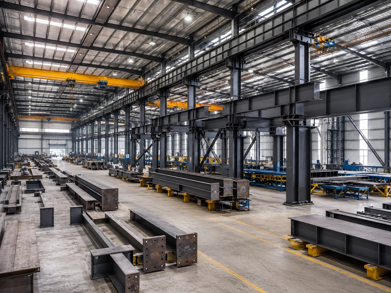
Connection stability depends on more than calculations. Plate cutting accuracy, fit-up, welding sequence, access, tolerances, and distortion control can influence the geometry that is ultimately delivered to site.
At XTD Steel Structure, coordination between structural detailing and fabrication helps ensure that stiffener dimensions, weld locations, clearances, and connection geometry remain consistent with the intended structural behavior. This is particularly important where relatively thin plates depend on defined edge restraint or close fit-up against the surrounding steelwork.
Shop drawings should therefore be reviewed not only for dimensional compliance but also for whether the fabricated detail preserves the load path assumed during stiffener buckling checks.
When a Different Connection Detail May Be More Efficient
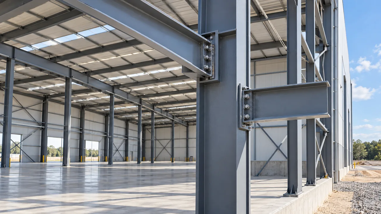
Adding reinforcement is not always the most economical response to a local connection limit state. In some cases, selecting a heavier column section can provide enough flange and web capacity to reduce or eliminate continuity plates or doubler plates. Other projects may benefit from revising beam size, connection geometry, end-plate configuration, or the arrangement of reinforcement.
The best solution depends on total project cost rather than plate weight alone. Material savings can be offset by additional cutting, fit-up, welding, inspection, and fabrication complexity.
For this reason, connection optimization should consider structural capacity and fabrication efficiency together. Well-planned stiffener buckling checks help designers identify when reinforcement is necessary and when a different connection strategy may provide a cleaner solution.
FAQ About Stiffener Buckling Checks
What Causes a Stiffener Plate to Buckle in a Moment Connection?
Buckling can occur when compressive force acts on a plate that is too slender or insufficiently restrained for the applied demand. Plate thickness, unsupported dimensions, boundary conditions, eccentricity, material properties, and fabrication imperfections can all influence the instability risk.
How Does Stiffener Thickness Affect Buckling Resistance?
Increasing thickness generally reduces the plate width-to-thickness ratio and improves resistance to local instability. However, thickness should be selected together with geometry, restraint, weld design, and fabrication requirements rather than treated as the only design variable.
Are Stiffener Buckling Checks Required if the Plate Passes Yielding?
Passing a yielding check does not automatically demonstrate stability. A slender plate can buckle before the full yielding resistance assumed by a simple area-based strength check is developed. Applicable buckling and slenderness provisions should therefore also be verified.
What Is the Difference Between Stiffener Buckling and Column Web Buckling?
Stiffener buckling refers to instability of the reinforcement plate itself. Column web buckling is a separate limit state involving the column web subjected to concentrated compression. Both may need evaluation within the same moment connection.
Do Full-Depth Stiffeners Have Better Buckling Resistance?
Full-depth stiffeners can benefit from restraint provided by both column flanges and the web, but their performance still depends on plate proportions, welds, fit-up, and loading. They should not be assumed adequate without the required design checks.
Can Increasing the Column Size Eliminate the Need for Stiffeners?
Yes. A larger or heavier column may provide sufficient flange and web resistance to reduce or eliminate reinforcement in some connections. The decision should compare structural efficiency with the material and fabrication cost of the alternatives.
Does Weld Detailing Affect Stiffener Buckling Behavior?
Yes. Weld detailing affects both force transfer and the restraint available along the stiffener boundaries. The analytical buckling model should therefore be consistent with the weld arrangement and actual fabricated condition.