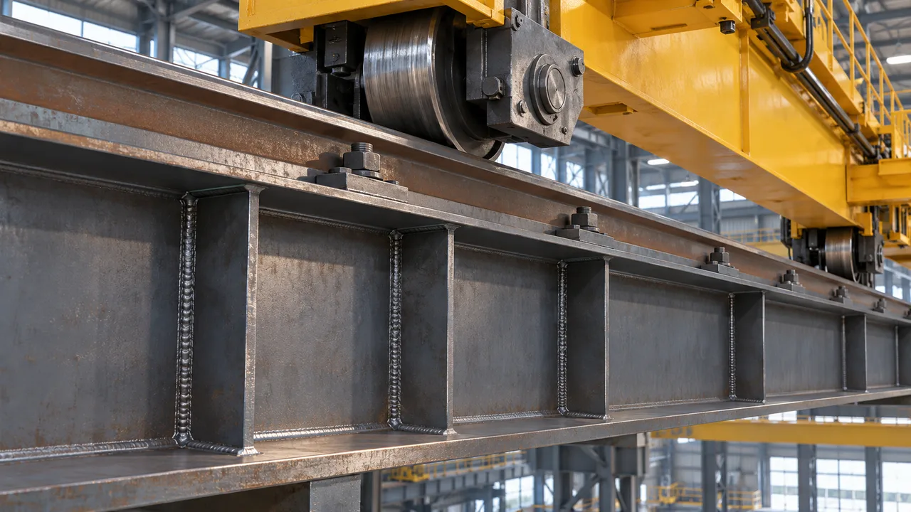
Crane beams and other heavy-duty steel members must transfer large concentrated forces through relatively small loading areas. Wheel reactions, support forces, machinery loads, and repeated operating cycles can create severe compression around the beam web. Transverse stiffeners are commonly introduced to strengthen these regions, improve load transfer, and stabilize slender web plates.
However, adding a stiffener does not automatically eliminate local instability. If its thickness, width, restraint, connection, or load alignment is inadequate, the stiffener itself can deform out of plane and lose its ability to carry compression effectively. For this reason, stiffener buckling in crane beams should be evaluated together with web behavior, flange stiffness, load eccentricity, welding details, and fabrication tolerances.
In heavy industrial structures, the most reliable solution is therefore not simply to add more steel. The complete load path must remain stable from the crane rail or concentrated load point through the flange, stiffener, web, and supporting structure.
What Is Stiffener Buckling in Crane Beams?
A transverse stiffener is typically a steel plate welded vertically to the web of an I-shaped or plate girder. Depending on its location and purpose, it may help resist concentrated transverse loads, stabilize a slender web, transfer reactions, or divide the web into smaller panels.
When a stiffener carries significant compression, it behaves as part of a compression system rather than as an infinitely rigid plate. Excessive slenderness or insufficient restraint can allow the plate to bend or buckle out of its original plane before its full compressive resistance is developed.
Stiffener buckling in crane beams must be distinguished from several related limit states. Stiffener yielding involves excessive stress in the stiffener material itself. Web yielding occurs in the beam web near a concentrated load. Web buckling involves instability of the web plate, while stiffener buckling specifically concerns instability of the reinforcing element and its effective surrounding section.
Why Crane Beams Are Vulnerable to Stiffener Buckling
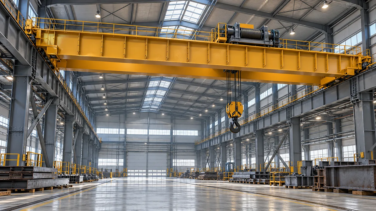
Concentrated Crane Wheel Loads
Crane wheels introduce large forces through rails positioned above the beam flange. These reactions are transferred from the rail into the flange and then into the web and surrounding stiffened region. When the load is high relative to the available load-transfer area, substantial compression can develop around the stiffener.
The situation becomes more demanding when wheel loads occur close to supports, stiffener locations, rail joints, or other regions where forces are already concentrated.
Repeated and Dynamic Loading
Industrial cranes do not produce purely static loading. Starting, stopping, braking, trolley movement, lifting operations, and impact effects create changing forces throughout the crane support system. A detail that appears adequate under a single idealized load case may behave differently when subjected to repeated cycles and small imperfections.
For this reason, crane beam design must consider not only ultimate resistance but also stiffness, deformation, fatigue-sensitive detailing, and the long-term condition of welded connections.
Deep and Slender Beam Webs
Heavy-duty plate girders are often relatively deep because increased beam depth can provide efficient bending resistance. However, increasing web depth without proportionally increasing web thickness creates a more slender plate. Transverse stiffeners may then become important for both local load transfer and web stability.
The design challenge is to create a stiffener arrangement that improves the web without introducing a new slender compression component.
How Stiffeners Transfer Loads Through a Crane Beam
The behavior of a stiffened crane beam is easier to understand by following its load path. A typical vertical crane reaction moves from the crane wheel into the rail, through the upper flange, and into the web and stiffener system. From there, the force is distributed through the beam toward the supports or other structural members.
Where a transverse stiffener is designed to carry concentrated compression, the stiffener plate and a portion of the adjacent web may participate together as an effective compression section. Their actual performance depends on geometry, material properties, boundary conditions, connection details, and the assumptions required by the applicable structural design standard.
If the stiffener is too slender or poorly restrained, out-of-plane deformation can interrupt this intended load path. The surrounding web can then experience higher deformation and localized stress than assumed in the original design.
Stiffener Buckling vs Web Local Yielding
Stiffener instability and web yielding can occur within the same load-transfer region, but they are different structural problems. Web local yielding develops when concentrated forces create excessive compressive stress in the web near a flange or load application zone. A stiffener may be added when the unstiffened web alone cannot provide sufficient resistance.
Once reinforcement is introduced, the designer must ensure that the stiffener can safely participate in carrying the force. A stiffener that is too thin, inadequately connected, or insufficiently restrained may buckle even though additional steel has been provided.
Where concentrated wheel loads or reactions act through the beam flange, designers should therefore evaluate web local yielding together with stiffener stability rather than treating them as unrelated checks.
Which limit state governs depends on the web slenderness, stiffener dimensions, flange geometry, load magnitude, load position, material properties, and restraint provided by surrounding components.
Main Causes of Stiffener Buckling in Crane Beams
Excessive Stiffener Slenderness
The relationship between the unsupported stiffener width and its thickness strongly influences local stability. A thin plate with a large outstand can deform more easily than a compact plate. Increasing thickness, reducing unsupported width, or improving restraint can increase stability, but the complete effective section should still be checked.
Insufficient Lateral Restraint
The theoretical capacity of a stiffener depends heavily on its boundary conditions. Connections to the web and flanges help restrain out-of-plane movement. If actual fabrication provides less restraint than assumed in analysis, the effective buckling length can increase and resistance can decrease.
Inadequate Plate Area
A stiffener must have sufficient cross-sectional area to carry the compression assigned to it. When wheel reactions or support forces increase while stiffener dimensions remain unchanged, compressive stress rises and stability becomes more critical.
Eccentric Load Transfer
The most efficient load path is generally one that minimizes unintended eccentricity. Misalignment between the crane rail, flange, web, bearing, or stiffener can introduce secondary bending into an element that may have been designed primarily for axial compression.
This interaction between compression and bending can significantly influence stiffener buckling in crane beams, especially when initial plate imperfections are also present.
Welding and Fabrication Distortion
Welding introduces heat into relatively thin steel plates. Uneven heating and cooling may produce residual stress, angular distortion, or initial curvature. These imperfections do not necessarily indicate unacceptable fabrication, but they should remain within appropriate tolerances because slender compression elements are sensitive to initial out-of-plane deformation.
Critical Design Checks for Stiffener Stability
Stiffener Slenderness
The stiffener plate should satisfy the relevant plate slenderness requirements for the applicable design method. Its thickness and unsupported outstand must be proportioned so that premature plate instability does not control the load-transfer system.
Effective Compression Section
Depending on the structural standard and stiffener configuration, part of the adjacent web may be considered together with the stiffener when evaluating compression resistance. Engineers should use the effective section permitted by the selected design code rather than assuming that an unlimited width of web participates.
Bearing and Compression Resistance
Where a stiffener transfers a concentrated reaction, both direct material resistance and overall stability are relevant. The design must also confirm that force can pass through the flange-stiffener-web assembly without creating an unintended weak point.
Buckling Length and Boundary Conditions
Stiffener capacity can change substantially depending on whether its ends behave as well restrained, partially restrained, or relatively flexible. The analytical model should reflect the actual detailing rather than relying on idealized restraint that cannot be achieved in fabrication.
Combined Compression and Bending
Real crane beam details rarely remain perfectly concentric. Rail positioning tolerances, support eccentricities, fabrication deviations, and deformation under load can all generate bending moments. Where relevant, the stiffener should therefore be checked for combined compression and bending rather than pure axial force alone.
Stiffener Arrangement in Heavy-Duty Crane Beams
| Design Factor | Potential Problem | Typical Design Response |
|---|---|---|
| Thin stiffener plate | Local plate buckling | Increase thickness or reduce unsupported width |
| Large stiffener outstand | High plate slenderness | Optimize stiffener geometry and restraint |
| High concentrated reaction | Excessive compression demand | Increase effective stiffener capacity |
| Eccentric rail or bearing position | Secondary bending | Improve alignment and check combined actions |
| Weak connection detailing | Reduced restraint or incomplete load transfer | Design appropriate welds and contact conditions |
| Slender web panel | Local web instability | Optimize transverse stiffener locations and spacing |
Stiffeners may be installed on one or both sides of the web depending on load level, structural configuration, fabrication requirements, and the governing design standard. Heavy concentrated loads often benefit from symmetrical arrangements because they can provide a more balanced load path and reduce unintended eccentricity.
Spacing is also important. Stiffeners should be positioned according to the structural behavior of the web panels and concentrated load locations rather than distributed at arbitrary intervals.
Fabrication Imperfections and Their Effect on Buckling
Structural calculations normally begin with an idealized geometry, while fabricated steel inevitably contains small deviations. Stiffener straightness, web flatness, flange alignment, weld shrinkage, and fit-up conditions can all influence real behavior.
A stiffener that is initially curved already has an out-of-plane displacement before the crane load is applied. Compression can magnify this deformation. The more slender the stiffener, the more sensitive its response may become.
Quality control should therefore include dimensional inspection as well as weld inspection. Accurate positioning is particularly important where stiffeners are intended to align with crane rail reactions, supports, diaphragms, or other concentrated load paths.
Connection Detailing Between Stiffener, Web, and Flange
Stiffener-to-Web Connections
The connection between the stiffener and web must transfer the forces assumed in structural analysis while providing the necessary restraint. Weld type, length, size, accessibility, and fabrication sequence should be coordinated rather than specified independently.
Stiffener-to-Flange Load Transfer
Where direct compression is intended to pass between a flange and stiffener, the detailing must provide a reliable load-transfer mechanism. Depending on the design concept, this may involve appropriate fitted contact, welding, or a combination defined by the engineer.
Stress Concentrations and Fatigue
Crane beams are fatigue-sensitive structural components because many details experience repeated stress fluctuations. Weld terminations, abrupt stiffness changes, poor fit-up, and unnecessary attachments can create local stress concentrations. Improving resistance to stiffener buckling in crane beams should therefore not introduce unnecessarily severe fatigue details elsewhere in the member.
Stiffener Buckling Under Repeated Crane Loading
Ultimate strength and fatigue performance address different aspects of structural behavior. A stiffener may possess adequate resistance to a single maximum design action while the surrounding welded detail still experiences a large number of stress cycles during normal crane operation.
Repeated loading can also make serviceability issues more visible. Local deformation, connection movement, rail misalignment, and existing imperfections may influence how forces are distributed during operation.
Heavy-duty crane beams should therefore be designed as complete systems in which stiffener stability, web behavior, fatigue resistance, rail alignment, and fabrication quality support one another.
How Engineers Can Reduce the Risk of Stiffener Buckling
Reducing the risk of stiffener buckling in crane beams begins with establishing a clear and realistic load path. Engineers should select sufficient plate thickness, control stiffener slenderness, provide appropriate restraint, and position reinforcing plates where concentrated forces actually enter the beam.
Eccentricities should not be ignored simply because the nominal structural geometry is symmetrical. Rail tolerances, support positioning, connection geometry, and construction tolerances may create secondary effects that deserve consideration.
The surrounding web must also remain part of the assessment. Strengthening one component without checking adjacent elements can simply transfer the governing failure mode to another location.
Stiffener Design Beyond Crane Beams
The same principles apply to many heavy-duty steel structures. Industrial transfer girders, machinery support beams, equipment platforms, large plate girders, warehouse crane systems, and structural members beneath concentrated reactions may all require localized web reinforcement.
In each case, stiffeners should be treated as structural elements with their own strength, stability, connection, and fabrication requirements rather than as secondary plates added after the main beam has already been designed.
From Design to Fabrication and Site Installation
Successful stiffener performance depends on accurate translation of the engineering model into shop drawings and fabricated steel. Drawings should clearly define stiffener dimensions, positions, weld requirements, connection conditions, and critical interfaces with the flanges and web.
During fabrication, dimensional control helps limit initial crookedness and ensures that stiffeners align with the intended load locations. During erection, the relationship between crane rail, beam centerline, supporting columns, brackets, and bearings should also be checked.
For projects involving heavy industrial loads, XTD Steel Structure integrates structural detailing with fabrication and installation considerations so that calculated load paths can be reproduced consistently in the finished steelwork.
Practical Design Perspective
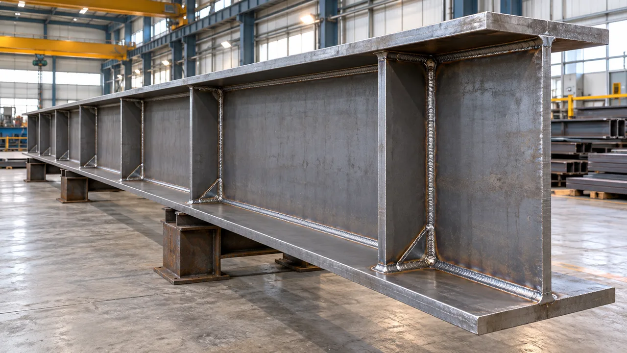
A stiffener cannot be evaluated independently from the web and flanges around it. Increasing plate thickness may improve one limit state, but it cannot correct a fundamentally poor load path, excessive eccentricity, inadequate connection, or severe fabrication distortion.
Efficient heavy-duty beam design balances web thickness, stiffener dimensions, stiffener spacing, flange geometry, welding requirements, fatigue performance, fabrication complexity, and installation tolerances. This system-level approach is particularly important when addressing stiffener buckling in crane beams, where concentrated and repeated loading can expose weaknesses that may remain insignificant in lightly loaded steel members.
Frequently Asked Questions
What Causes Stiffener Buckling in Crane Beams?
Common causes include excessive stiffener slenderness, inadequate thickness, insufficient restraint, high compression, eccentric loading, poor load alignment, and fabrication imperfections. Several of these effects may occur simultaneously in heavy-duty crane beams.
How Can Stiffener Buckling Be Prevented?
Engineers can improve stability by selecting appropriate stiffener dimensions, limiting plate slenderness, providing reliable restraint and connections, controlling eccentricity, and verifying the effective stiffener section for the required compression and bending actions.
Is Stiffener Buckling the Same as Web Buckling?
No. Stiffener buckling refers primarily to instability of the reinforcing stiffener and its effective compression section. Web buckling refers to instability of the beam web plate. The two behaviors can interact, which is why both should be considered in a complete design.
When Are Bearing Stiffeners Required in Crane Beams?
Bearing or load-carrying stiffeners may be required when the unstiffened web cannot safely resist concentrated transverse forces or when the structural system requires a more direct load-transfer path. The exact requirement depends on beam geometry, loading, material properties, and the applicable design standard.
Does Stiffener Thickness Affect Crane Beam Fatigue Performance?
Thickness influences stiffness and local stress distribution, but fatigue performance is also strongly affected by weld geometry, stress range, connection detailing, fabrication quality, and discontinuities. Simply increasing stiffener thickness does not automatically produce a better fatigue detail.
Can Welding Distortion Reduce Stiffener Buckling Capacity?
Welding can introduce initial curvature, residual stress, and angular distortion. These imperfections can influence the stability of slender compression elements, making fabrication sequence, dimensional tolerances, and inspection important parts of heavy-duty stiffener design.