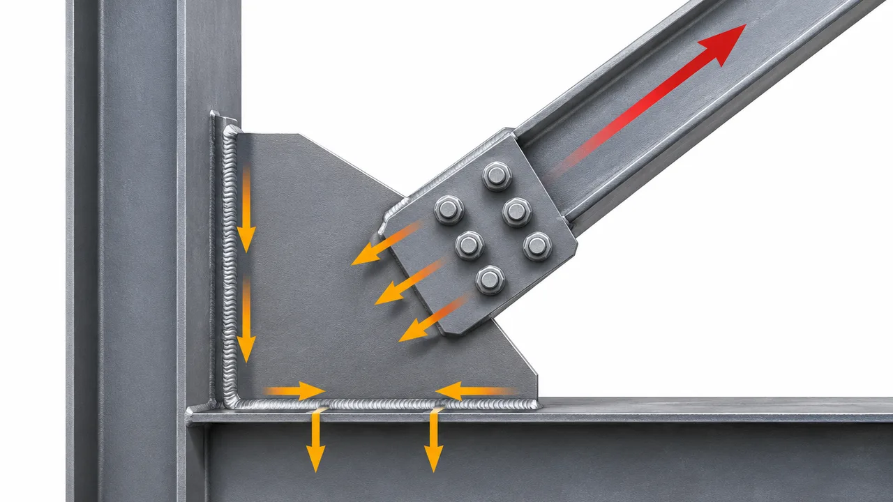
Gusset plates are critical connection components in steel bracing systems because they transfer forces between braces and the primary structural frame. Depending on the connection arrangement, these forces may pass through bolts, welds, the gusset plate itself, and finally into beams, columns, or beam-column joints. For this reason, evaluating weld and bolt capacity in gusset plates requires more than checking the strength of individual fasteners or weld segments.
The actual connection capacity depends on the complete load path. Bolt shear, bolt tension, weld resistance, plate bearing, net-section fracture, block shear, gusset plate yielding, and buckling can all influence the final resistance. A strong bolt group does not guarantee a strong connection if the gusset plate fails first, while a large weld may provide little additional benefit when the surrounding base metal controls the design.
How Gusset Plate Braced Connections Transfer Forces
Force Flow from the Brace to the Gusset Plate
Steel braces primarily transfer axial forces generated by wind, seismic action, structural movement, or other lateral loading. These forces may act in tension, compression, or alternate between both conditions depending on the structural system.
When a brace is bolted to a gusset plate, the axial brace force enters the bolt group and is transferred through bolt shear, bearing, friction, or a combination of these mechanisms. When the brace is welded directly to the gusset, the force moves through the weld group into the plate.
The connection geometry determines how evenly these forces are distributed. Eccentricity between the brace centerline and the centroid of the bolt or weld group can generate additional moments that increase demand on individual connection components.
Force Transfer from the Gusset Plate to the Main Frame
After the force enters the gusset plate, it must continue into the surrounding structural system. The gusset may be connected to a beam, column, beam-column joint, or another supporting member through welding, bolting, or a combination of both.
The connection between the gusset plate and the supporting frame must therefore resist the same structural force that enters through the brace. Weld length, weld size, bolt arrangement, plate dimensions, and local behavior of the supporting member all influence this transfer.
Why the Complete Load Path Matters
A gusset plate braced connection includes several components that work together rather than independently. The brace transfers force into bolts or welds, the gusset plate distributes that force, and the beam or column receives the resulting load.
If one component has significantly lower resistance than the others, it can govern the entire connection. Engineers therefore evaluate the complete load path instead of assuming that stronger bolts or larger welds automatically increase overall connection capacity.
Weld and Bolt Capacity in Gusset Plates
Weld Capacity in Gusset Plate Connections
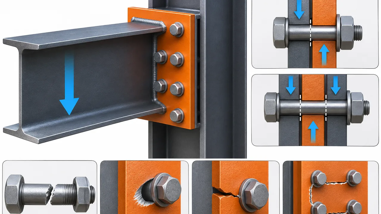
Welded gusset plate connections commonly use fillet welds because they are practical for attaching plates to beams, columns, and other structural components. Groove welds may also be used when greater penetration or more direct force transfer is required.
Weld resistance depends on weld size, effective throat, effective length, filler metal strength, base metal strength, loading direction, and the geometry of the weld group. The surrounding plate and supporting structural member must also be checked because the connected material may yield or fracture before the weld itself reaches its theoretical capacity.
Bolt Capacity in Gusset Plate Connections
Bolted gusset plate connections may transfer forces through bolt shear, bolt tension, bearing between the bolt and plate, or friction in slip-critical connections. The capacity of the bolt group depends on bolt diameter, bolt grade, number of bolts, number of shear planes, bolt spacing, edge distance, plate thickness, and loading condition.
Bolt capacity cannot be evaluated independently from the gusset plate. Bolt holes reduce the net plate area and can introduce failure modes such as net-section fracture, block shear, bearing deformation, and edge tear-out.
Why Weld and Bolt Capacity Must Be Checked Together
Many braced connections use both welding and bolting. A gusset plate may be welded to the beam or column in the fabrication shop while the brace is bolted to the gusset during erection.
In these arrangements, the bolt group and weld group belong to the same load path. Strong bolts provide little benefit if the weld attaching the gusset to the supporting member is inadequate. Likewise, a strong weld does not compensate for insufficient bolt resistance or a weak gusset plate.
For this reason, weld and bolt capacity in gusset plates should always be evaluated together with the capacity of the connected plate and structural members.
Load Conditions Affecting Gusset Plate Connections
Axial Tension
When a brace is subjected to tension, force is pulled through the connection. Bolts may resist shear or tension depending on the connection geometry, while the gusset plate must resist bearing, yielding, net-section fracture, and block shear.
Welded connections must transfer the same tensile force through the weld group and surrounding base metal. Plate dimensions and force distribution determine whether local or global yielding develops.
Axial Compression
Compression braces push force into the gusset plate. The welds or bolts must transfer the required force, but connection strength alone is not sufficient. The gusset plate must also remain stable under compression.
A thin gusset plate with adequate weld and bolt strength may still buckle if its unsupported length is excessive or if the geometry provides insufficient restraint.
Reversed and Cyclic Loading
Bracing systems may experience repeated reversal between tension and compression under wind or seismic loading. These load reversals can affect bolt behavior, weld performance, gusset plate deformation, and fatigue-sensitive details.
Connections subjected to cyclic loading should provide a predictable load path and sufficient ductility for the intended structural behavior.
Eccentric Loading
The brace work point does not always align perfectly with the centroid of the bolt or weld group. This offset creates eccentricity and can introduce additional moments into the connection.
Eccentric loading may cause uneven bolt forces or nonuniform stresses along the weld group. Ignoring this effect can lead to an overestimation of connection capacity.
Factors That Determine Weld Capacity
Weld Size and Effective Throat
The effective throat is one of the main factors controlling fillet weld resistance. Increasing weld size generally increases the effective throat and available resistance, but larger welds are not automatically more efficient.
If the gusset plate or supporting member controls the connection, increasing the weld size may not improve the overall capacity.
Effective Weld Length
Longer welds can provide greater resistance when the load is distributed effectively. However, extremely long weld groups may experience nonuniform stress distribution, especially when force enters the connection eccentrically.
Weld Orientation
Weld resistance and stress distribution depend on the direction of loading relative to the weld axis. Longitudinal, transverse, and angled welds can behave differently under the same applied force.
Filler Metal and Base Metal Strength
The filler metal must provide sufficient resistance for the required weld force. At the same time, the base metal surrounding the weld must remain capable of transferring the load without yielding or fracture.
Eccentricity of the Weld Group
If the applied load does not pass through the centroid of the weld group, the weld must resist both direct force and the additional moment caused by eccentricity. This can significantly increase demand on individual weld segments.
Access and Welding Quality
A theoretically adequate weld can perform poorly if the fabrication conditions do not allow proper access, fit-up, sequencing, or inspection. Weld quality therefore forms an important part of practical connection capacity.
Factors That Determine Bolt Capacity
Bolt Diameter and Grade
Larger-diameter and higher-strength bolts can generally resist greater loads. However, increasing bolt strength alone may shift the governing failure mode into the gusset plate.
Number of Bolts
Additional bolts can increase the nominal capacity of a bolt group, but increasing the number of holes also reduces the available net area of the gusset plate. The bolt layout must therefore be coordinated with plate dimensions.
Bolt Spacing and Edge Distance
Bolt spacing and edge distance influence bearing resistance, tear-out resistance, constructability, and the ability to install and tighten fasteners correctly.
Bolt Shear and Bearing
In bearing-type connections, the bolt may resist shear while its shank bears against the plate. Both the bolt and plate must provide sufficient resistance for the applied load.
Bolt Tension and Combined Loading
Some connection geometries introduce bolt tension in addition to shear. Combined loading may reduce the available resistance compared with separate shear or tension conditions.
Slip-Critical Requirements
Slip-critical connections use pretensioned bolts and prepared faying surfaces to resist movement through friction. Where slip must be limited, the slip resistance may control before conventional bearing resistance becomes critical.
Gusset Plate Limit States That Can Control the Connection
Plate Bearing at Bolt Holes
High local pressure between the bolt shank and the hole can deform the gusset plate. Plate thickness, bolt diameter, spacing, edge distance, and material strength all influence bearing resistance.
Net-Section Fracture
Bolt holes reduce the effective cross-sectional area of the gusset plate. If the remaining net section is insufficient, fracture can develop across a line of bolt holes.
Block Shear
Block shear combines tensile and shear failure around a bolt group. It is influenced by bolt layout, edge distances, plate dimensions, and material strength.
Edge Tear-Out
A bolt located too close to the plate edge can cause the material between the hole and edge to tear out. Adequate edge distance is therefore necessary for reliable force transfer.
Gross-Section Yielding
The gross section of the gusset plate must have sufficient area to transfer the applied force without excessive yielding.
Gusset Plate Buckling
Compression can cause the gusset plate to buckle even when its welds and bolts have adequate strength. Plate thickness, unsupported length, connection geometry, and boundary conditions strongly influence this behavior.
Local Yielding Near Welded Regions
High stresses near weld terminations or concentrated load paths may cause localized yielding in the gusset plate or supporting member. This behavior should be considered together with weld resistance.
Welded vs Bolted Gusset Plate Connections
| Factor | Welded Gusset Connection | Bolted Gusset Connection |
|---|---|---|
| Force transfer | Continuous through the weld | Through individual bolts |
| Shop fabrication | Excellent | Excellent |
| Site erection | More difficult when field welding is required | Usually faster |
| Adjustability | Limited | Better during erection |
| Inspection | Weld inspection may be required | Generally more straightforward |
| Modification | More difficult | Usually easier |
| Bolt holes | Not required | Reduce net plate area |
| Heat input | Present during welding | Minimal |
| Typical use | Shop-fabricated connections | Field assembly |
Welded Gusset Plates in Shop Fabrication
Controlled Welding Conditions
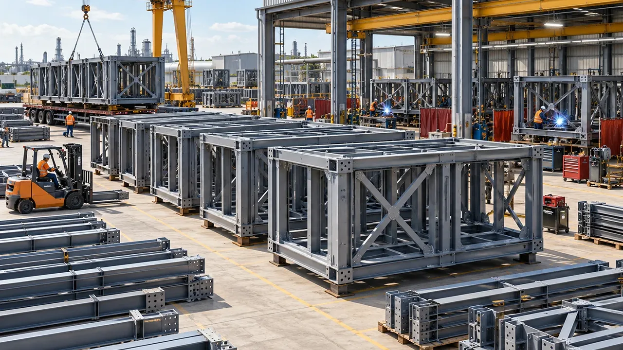
Shop welding provides better control over fit-up, welding procedures, positioning, heat input, inspection, and distortion than many field environments. Proper fabrication sequencing can also reduce residual deformation and improve dimensional accuracy.
Preparing Connections Before Erection
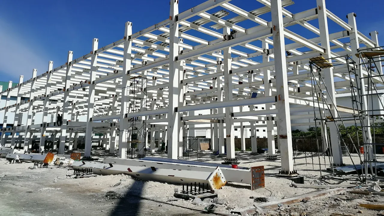
Gusset plates are frequently welded to beams or columns during fabrication and transported to the construction site as part of the structural assembly. The brace can then be bolted to the prepared gusset during erection.
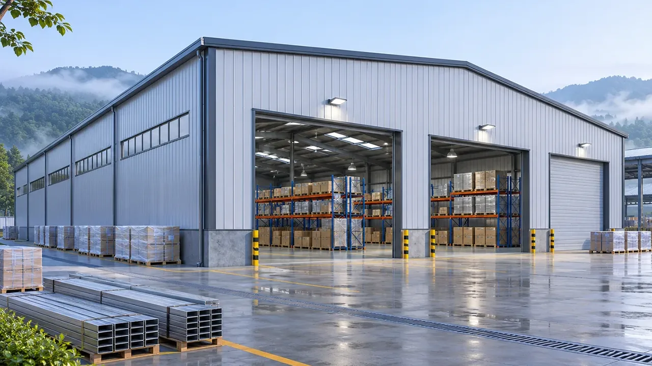
This approach is particularly useful for a Steel structure warehouse, where repeated bracing connections and prefabricated frames benefit from controlled shop fabrication and efficient site assembly. XTD Steel Structure uses coordinated fabrication and connection detailing to prepare structural components before transportation whenever project conditions allow.
Bolted Gusset Plates for Site Assembly
Faster Erection
Bolted connections allow erection crews to position braces and install fasteners without extensive field welding. This can reduce installation time and simplify site operations.
Easier Alignment
Bolt holes provide a practical means of positioning and aligning structural members during erection. Proper fabrication tolerances remain essential to ensure holes align correctly.
Practical Inspection
Bolt quantity, grade, placement, and tightening condition can often be inspected directly. Where pretension is required, suitable installation and verification procedures must be followed.
Future Modification or Replacement
Bolted braces may be easier to remove or replace when a structure is modified, expanded, or repaired.
Combined Welded and Bolted Gusset Plate Connections
Many steel bracing systems use a combination of welding and bolting. A common arrangement is to weld the gusset plate to the beam or column in the shop and bolt the brace to the gusset during site erection.
This configuration combines controlled shop welding with the speed and flexibility of field bolting. It also reduces the amount of welding required at the construction site while allowing braces to be transported separately.
However, combining connection methods does not eliminate the need for complete design checks. The bolt group, weld group, gusset plate, brace, and supporting members must all provide sufficient resistance along the same force path.
Effect of Gusset Plate Geometry on Weld and Bolt Capacity
Plate Thickness
Increasing gusset plate thickness can improve bearing resistance, gross-section capacity, block shear resistance, and compression stability. However, unnecessary thickness can increase material cost and connection weight.
Plate Width and Connection Length
Plate width determines the available section for force transfer, while connection length influences bolt arrangement, weld length, and stress distribution.
Brace Angle
The brace angle affects the direction of force entering the gusset plate and can influence the geometry of the weld and bolt groups.
Bolt Group Layout
Bolt quantity, spacing, row arrangement, and connection length affect load distribution and plate failure modes.
Weld Layout
The position and length of welds influence how forces enter the beam or column. Balanced weld layouts can help reduce connection eccentricity.
Edge Distance
Adequate edge distance helps prevent tear-out and provides sufficient material around bolt holes.
Clearance for Rotation and Deformation
Some bracing systems require gusset plates to accommodate deformation or rotation under significant structural loading. Connection geometry should support the intended structural behavior rather than unnecessarily restraining it.
Connection Design for Tension Braces
Tension braces pull force through the gusset plate connection. Engineers typically evaluate bolt shear, bolt bearing, net-section fracture, block shear, weld resistance, and yielding of the plate.
The effective section available for transferring tension also depends on how the load spreads through the gusset plate. Concepts such as an effective width through the plate help engineers evaluate whether the available section can carry the brace force.
The connection must ultimately transfer the brace tension into the supporting frame without creating a weaker failure path in the gusset plate or adjacent structural members.
Connection Design for Compression Braces
Compression braces push load into the gusset plate. The bolt and weld groups must transfer this force, but compression behavior introduces an additional concern: plate stability.
A gusset plate can buckle even if the connection fasteners have adequate nominal strength. Unsupported length, plate thickness, brace geometry, edge restraint, and connection stiffness therefore become important design parameters.
This demonstrates why bolt and weld resistance alone cannot determine the capacity of a compression-brace connection.
Seismic and Reversible Bracing Considerations
Braced frames subjected to seismic or other reversible loading may cycle repeatedly between tension and compression. Under these conditions, connection ductility and predictable deformation become particularly important.
The gusset plate may need to accommodate rotation or inelastic deformation, while bolts and welds must continue transferring the required forces. Slip behavior, weld fracture, plate buckling, and local yielding may all influence the response.
Specific seismic detailing requirements depend on the applicable structural design standard, structural system, project location, and required performance level. Connection geometry should therefore be coordinated with the relevant engineering requirements rather than relying on one universal detail.
Fabrication and Installation Considerations
Weld Quality Control
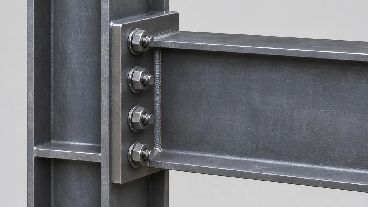
Reliable weld performance depends on qualified personnel, suitable procedures, correct fit-up, controlled heat input, appropriate sequencing, and proper inspection. Visual examination and nondestructive testing may be required depending on the project and connection category.
Bolt Installation Control
Bolted gusset connections require the correct bolt grade, accurate hole alignment, appropriate washers, proper pretension where required, and controlled tightening procedures.
Fabrication Tolerances
Gusset plate location, bolt-hole position, brace alignment, and weld distortion must all remain within suitable fabrication tolerances. Dimensional errors can create fit-up problems during erection and may introduce unintended eccentricity into the final connection.
How Engineers Check Weld and Bolt Capacity in Gusset Plates
A systematic connection check typically follows this sequence:
- Determine the axial force acting in the brace.
- Identify whether the brace is subjected to tension, compression, or reversible loading.
- Establish the complete load path through the gusset plate.
- Determine the forces acting on the bolt group.
- Check bolt shear, tension, and interaction where applicable.
- Check plate bearing around bolt holes.
- Determine the forces acting on the weld group.
- Check weld size, effective length, and eccentricity.
- Check gusset plate yielding and fracture.
- Check block shear and net-section resistance.
- Evaluate gusset plate buckling under compression.
- Check the attachment to the beam, column, or supporting member.
- Review fabrication, installation, and inspection requirements.
- Confirm that the lowest applicable resistance exceeds the required structural demand.
This process shows why weld and bolt capacity in gusset plates must be treated as part of the complete connection rather than as separate calculations for fasteners and welds.
Common Design Mistakes
- Checking bolt strength while ignoring plate bearing
- Checking weld strength while ignoring the base metal
- Ignoring net-section loss caused by bolt holes
- Providing insufficient bolt edge distance
- Using inadequate bolt spacing
- Ignoring block shear
- Oversizing welds without improving total connection capacity
- Ignoring weld-group eccentricity
- Ignoring gusset plate buckling under compression
- Assuming tension and compression behavior are identical
- Ignoring brace work-point eccentricity
- Providing insufficient access for bolting or welding
- Ignoring fabrication tolerances
- Treating weld and bolt capacity as isolated checks
Frequently Asked Questions
What Controls the Capacity of a Gusset Plate Braced Connection?
The governing capacity may be controlled by bolt shear, bolt tension, weld fracture, plate bearing, net-section fracture, block shear, gusset plate yielding, plate buckling, base metal failure, or another connected component. The lowest applicable resistance generally governs the final connection capacity.
How Is Weld Capacity Checked in a Gusset Plate Connection?
Weld capacity is evaluated using factors including weld type, weld size, effective throat, effective length, filler metal strength, loading direction, weld-group geometry, eccentricity, and the strength of the surrounding base metal.
How Is Bolt Capacity Checked in a Gusset Plate Connection?
Bolt capacity may require checks for shear, tension, combined loading, bearing, slip resistance, and interaction with the gusset plate. The plate around the bolt holes must also be checked for bearing, tear-out, net-section fracture, and block shear.
Can a Gusset Plate Be Welded and Bolted in the Same Connection?
Yes. Combined welded and bolted arrangements are common. A gusset plate may be welded to the main frame in the fabrication shop while the brace is bolted to the plate during erection.
Can the Gusset Plate Fail Before the Welds or Bolts?
Yes. The gusset plate may fail through bearing, yielding, net-section fracture, block shear, tear-out, or buckling even when the welds and bolts individually have adequate resistance.
Why Are Gusset Plates Often Welded in the Shop and Bolted on Site?
Shop welding provides better control of fabrication quality, while site bolting generally allows faster erection and easier alignment. Combining the two methods can improve both fabrication efficiency and field constructability.
Conclusion
Weld and bolt capacity in gusset plates cannot be evaluated by looking only at bolt strength or weld resistance. The brace, bolts, welds, gusset plate, beam, column, and supporting components form one continuous load path, and the weakest applicable limit state determines the actual connection capacity.
Welded gusset connections can provide compact and efficient force transfer, while bolted connections often improve erection speed, adjustability, and inspection. Combined welded and bolted arrangements frequently provide an effective balance between shop fabrication quality and site installation efficiency.
The final connection should therefore balance structural capacity, gusset plate behavior, fabrication quality, erection requirements, inspection, durability, and predictable structural performance throughout the complete load path.