North light truss design is not only about creating a distinctive roof shape. It is a coordinated design approach that combines steel roof structure, daylight direction, roof slope, glazing placement, load transfer, ventilation, drainage, fabrication, and installation planning. When these elements are planned together, a north light truss can provide both structural support and controlled natural daylight for large industrial spaces.
This type of roof system is commonly used in factories, workshops, production halls, warehouses, and other steel buildings where interior visibility matters. Instead of relying only on artificial lighting, the roof geometry allows daylight to enter through a controlled face of the roof. At the same time, the steel truss system supports roof panels, glazing frames, purlins, bracing, and environmental loads.
A successful design must balance two goals: the roof must be strong as a structural system, and the daylighting strategy must work in real building conditions. If the glazing direction, roof slope, load path, drainage, or bracing is poorly coordinated, the roof may become difficult to fabricate, expensive to install, or uncomfortable inside the building.
What Is North Light Truss Design?
North light truss design is the process of planning a steel roof truss system with an asymmetric roof profile that allows natural daylight to enter through one side of the roof. The light-facing side is often steeper and may include glazing, translucent panels, or other daylighting materials. The other side usually supports opaque roof cladding and helps protect the building from weather.
The main idea is to bring indirect natural light into a large interior area without excessive glare or heat gain. This is why north light roof forms have long been associated with industrial buildings, especially spaces where workers need stable lighting for production, assembly, inspection, or storage operations.
Unlike a basic pitched roof truss, a north light truss must be designed with daylight direction in mind. The roof shape, building orientation, sun path, local climate, glazing angle, and internal working layout all influence the final design. The structure is not just supporting the roof; it is also shaping how light enters the building.
How a North Light Truss Works in Steel Roof Structures
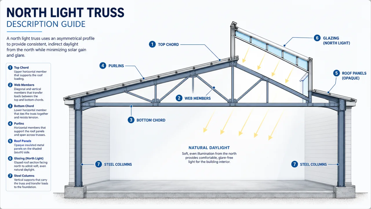
A north light truss works as part of a complete steel roof structure. The truss carries the roof load, while the daylight-facing roof plane introduces natural light. Purlins transfer loads from roof panels and glazing frames into the truss. Bracing keeps the roof stable, and gutters or drainage details remove rainwater from the roof surface.
The upper chord follows the roof geometry and supports roof loads through the purlins. The lower chord ties the truss together and helps resist spreading forces. Web members connect the upper and lower chords, dividing the span into smaller structural zones. This triangular arrangement helps transfer forces efficiently through the steel members.
Because the roof shape is not symmetrical in many north light systems, load paths must be reviewed carefully. The glazed side, opaque side, purlin spacing, wind exposure, and drainage direction can all influence the force distribution. A design that looks simple in elevation may still require detailed engineering to ensure stability and long-term performance.
Daylighting Benefits of North Light Truss Design
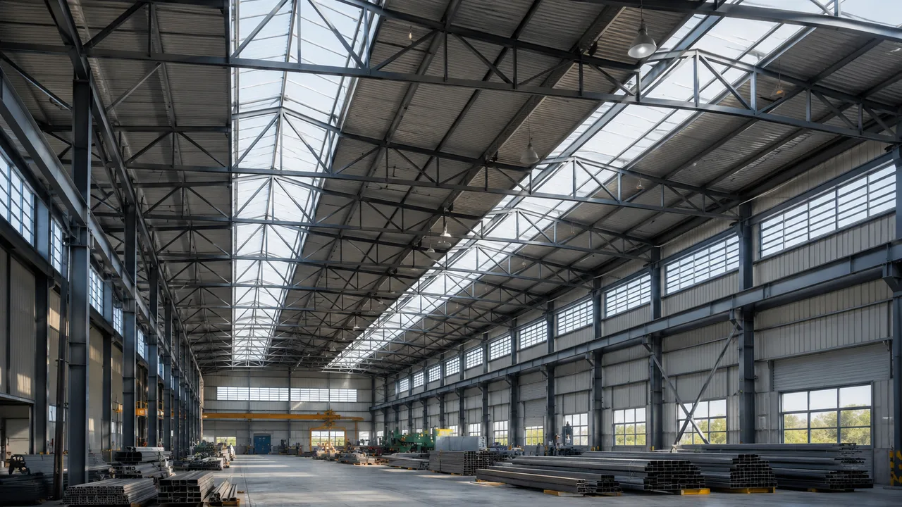
One of the main reasons to use a north light roof system is daylighting. In industrial buildings, natural light can improve visibility, reduce daytime dependence on artificial lighting, and create a more comfortable working environment. For production halls, fabrication workshops, inspection areas, and storage spaces, consistent daylight can support daily operations.
The key advantage is controlled daylight. Compared with direct skylights, a north light truss can admit softer light from a specific direction. This can help reduce strong glare, sharp shadows, and unwanted heat gain when the roof orientation is properly planned.
Daylighting benefits may include:
- Better indoor visibility during daytime operations
- Reduced use of artificial lighting during daylight hours
- More even light distribution across large floor areas
- Improved working conditions in workshops and factories
- Reduced glare compared with uncontrolled overhead openings
- Better integration between roof structure and building performance
However, daylighting is not automatic. Too much glazing can increase heat, glare, maintenance needs, and waterproofing risk. Too little glazing may not provide enough natural light. The best result comes from balancing glazing area, orientation, roof slope, building use, and local climate.
Roof Orientation and Light Direction
Orientation is one of the most important parts of north light truss planning. The roof must be positioned so the daylighting face receives the intended light quality. In many regions, a north-facing light surface is used to reduce direct solar glare and bring softer daylight into the interior. However, the correct orientation depends on the project location, hemisphere, latitude, sun path, and building layout.
This is why roof orientation should be confirmed early. If the building is rotated after the roof geometry has been developed, the daylighting performance may change. A roof face that was intended to provide soft indirect light may receive stronger direct sun, increasing heat gain and glare.
For practical projects, orientation should be reviewed together with:
- Local sun path and seasonal daylight angle
- Building use and working area layout
- Glazing angle and glazing material
- Internal heat control requirements
- Roof drainage direction
- Prevailing wind and rain exposure
- Neighboring buildings or site obstructions
Good orientation improves the value of the roof system. Poor orientation can turn a daylighting feature into a heat, glare, or waterproofing problem.
Structural Components in a North Light Truss
A north light truss is made of several steel components that must work together. The final performance depends not only on the main truss members, but also on purlins, bracing, connections, glazing frames, and roof panels.
Top Chord
The top chord follows the roof slope and receives loads from purlins, roof panels, glazing, insulation, and environmental forces. In many cases, the top chord works mainly in compression. Because compression members can buckle, the top chord usually needs lateral restraint from purlins and roof bracing.
In north light trusses, the top chord geometry may differ between the glazed roof side and the opaque roof side. This makes accurate detailing important. The purlin layout, glazing support, connection plate angles, and drainage direction should be coordinated with the top chord from the beginning.
Bottom Chord
The bottom chord connects the lower ends of the truss and helps resist horizontal spreading forces. It often works in tension, depending on the load condition and support arrangement. In some buildings, the bottom chord may also support ceilings, lights, cable trays, or small suspended services.
These service loads should not be added casually after fabrication. If the bottom chord will carry suspended items, the load points and allowable loads must be included in the design.
Web Members
Web members transfer forces between the top and bottom chords. They divide the span into smaller triangular zones, helping the truss carry loads efficiently. Proper alignment is important because misaligned web members can create eccentric forces and connection problems.
In steel fabrication, web members should be cut, drilled, welded, and marked accurately. CNC processing and clear shop drawings help maintain the intended geometry, especially when many trusses are repeated across a long building.
Purlins and Roof Panels
Purlins connect the roof covering system to the truss. They transfer loads from roof panels and glazing frames into the main steel members. Their spacing must match the roof panel requirements, glazing support requirements, and structural design.
Roof panels must also be coordinated with waterproofing details. Where opaque panels meet glazing or translucent panels, the detailing must prevent leakage and allow for thermal movement.
Bracing System
Bracing is essential for stability. Permanent bracing helps the roof structure resist lateral forces and prevents buckling during service. Temporary bracing helps keep the trusses stable during erection before the full roof system is complete.
A truss may be strong in its final condition but unstable during installation if temporary bracing is not planned. This is especially important for long-span steel roof structures and buildings exposed to wind during construction.
Load Considerations in North Light Truss Design
Structural loads must be clearly defined before the truss is finalized. A north light roof may include steel members, roof panels, glazing, purlins, insulation, gutters, maintenance access, wind forces, and suspended services. Each load affects the structure differently.
Dead loads include the self-weight of steel, roof sheets, glazing, insulation, fasteners, gutters, and other permanent materials. Live and maintenance loads include workers, tools, access equipment, and roof maintenance requirements. Wind load is especially important because sloped and glazed roof faces can experience uplift and pressure changes. In some climates, rainwater accumulation or snow load may also influence the design.
Suspended loads require special attention. Lighting systems, ventilation ducts, fire pipes, cable trays, and small platforms can become significant when repeated across a large building. A good design should define where services may be attached and how much load each connection point can support.
Glazing and Roof Panel Coordination
Glazing is the feature that gives a north light roof its daylighting value, but it also adds design complexity. The glazing area must be large enough to admit useful daylight but controlled enough to limit heat gain, glare, leakage risk, and maintenance problems.
The glazing frame must be compatible with the steel truss and purlin system. It must resist wind pressure, support its own weight, allow water runoff, and connect securely to the surrounding roof structure. If the glazing is treated as an afterthought, it can cause alignment issues, leakage, thermal movement problems, or difficult site installation.
Important glazing coordination points include:
- Glazing angle and direction
- Frame connection to steel members
- Waterproofing around edges and joints
- Compatibility with roof panels and flashing
- Thermal movement and expansion gaps
- Cleaning and maintenance access
- Protection from impact or construction damage
A practical north light roof must be easy to build and maintain, not only attractive in design drawings.
Ventilation and Heat Control
Daylighting and thermal comfort must be planned together. A roof that brings in natural light may also bring heat if the glazing area, orientation, or ventilation strategy is poorly designed. In factories and workshops, heat buildup can affect worker comfort, equipment operation, and energy use.
Ventilation can be natural, mechanical, or combined. Ridge vents, side louvers, operable windows, exhaust fans, and wall openings may all support airflow. Insulated roof panels, reflective surfaces, and controlled glazing materials can also help reduce unwanted heat gain.
The goal is not simply to bring more light into the building. The goal is to bring useful daylight while keeping the interior practical for daily operation.
North Light Truss vs Saw-Tooth Truss
North light truss and saw-tooth truss systems are both associated with daylighting roof design, but they are not always the same solution. A north light truss usually focuses on admitting controlled directional daylight through a specific roof face. A saw-tooth truss often uses repeated roof profiles, with steep or vertical light-facing surfaces across a larger roof area.
The best choice depends on the building span, lighting target, drainage strategy, fabrication complexity, roof height, internal layout, and architectural requirements. For a closer comparison between two daylighting roof systems, see this guide on north light truss vs saw-tooth truss.
In many projects, the decision is not only visual. It affects steel tonnage, purlin layout, waterproofing details, glazing cost, installation sequence, and long-term maintenance.
Applications of North Light Truss Design
North light truss design can be suitable for different types of steel buildings when daylighting, roof structure, and building use are aligned.
Factory Buildings
Factories often need stable natural light for production, assembly, inspection, and equipment operation. A north light roof can help illuminate large floor areas while maintaining an efficient steel roof structure.
Workshops
Workshops used for fabrication, repair, assembly, or machinery work can benefit from controlled daylight. The roof design should also consider ventilation, suspended tools, cable trays, and future service upgrades.
Warehouses
Warehouses may use north light roof systems to reduce daytime lighting demand in large storage spaces. However, glare, heat, racking layout, and fire systems should be reviewed carefully.
Agricultural and Processing Buildings
Agricultural and processing buildings may benefit from daylight and ventilation together. Corrosion protection, moisture control, and cleaning access are important in these environments.
Industrial Facilities
Industrial facilities often require a roof system that supports operations, services, maintenance, and long-term durability. A north light truss can be effective when the structure and daylighting plan are coordinated from the start.
Fabrication Considerations for Steel North Light Trusses
Fabrication should be considered during design, not after engineering is finished. Complex roof geometry, angled members, glazing support frames, connection plates, and transport segments can all affect cost and schedule.
Important fabrication factors include:
- Accurate cutting of top chord, bottom chord, and web members
- CNC drilling for bolt alignment
- Gusset plate thickness and connection detailing
- Welding sequence and deformation control
- Trial assembly for complex roof sections
- Surface preparation, painting, or galvanizing
- Segment size for container loading or truck transport
- Clear member marking for site installation
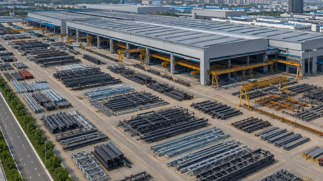
For export steel structure projects, packaging and erection logic are especially important. XTD Steel Structure typically treats fabrication accuracy, member marking, and site assembly planning as part of the same delivery system, because small fabrication errors can become expensive installation problems.
Installation Planning
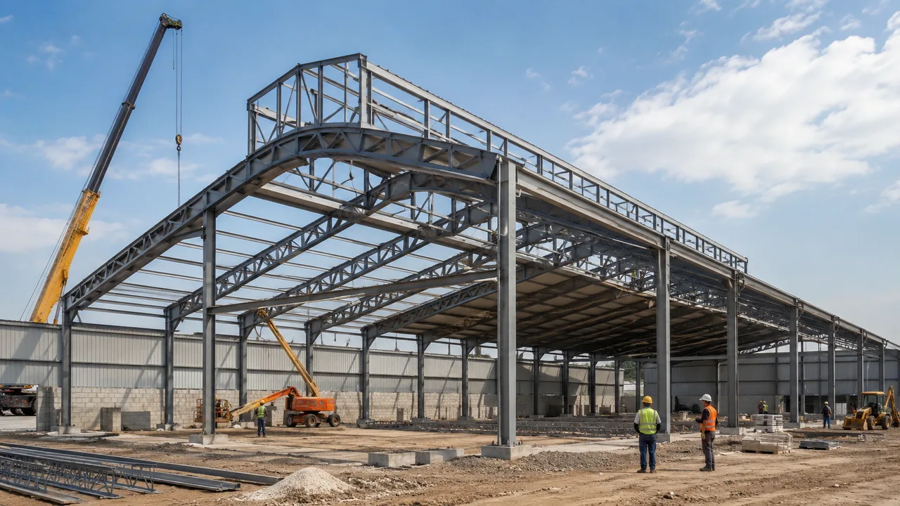
Installation planning affects safety, speed, and roof performance. A north light roof may require careful sequencing because the steel truss, purlins, bracing, glazing frames, roof panels, flashing, and gutters must be installed in the right order.
Large trusses need proper lifting points and crane access. Temporary bracing must be installed before the structure is exposed to unstable conditions. Purlins and permanent bracing should be installed early enough to help stabilize the roof system. Glazing installation should usually happen after the steel frame is aligned and checked.
Final inspection should review bolt tightening, weld quality where applicable, member alignment, coating damage, waterproofing details, glazing support, and completion of the bracing system. A roof that is designed well can still fail in performance if installation details are rushed.
Common Design Mistakes in North Light Truss Design
| Common Mistake | Why It Matters | Better Approach |
|---|---|---|
| Poor roof orientation | The daylighting face may receive too much direct sun or too little useful daylight. | Review sun path, latitude, climate, and building layout before final roof geometry. |
| Too much glazing | Excess glazing can increase heat gain, glare, leakage risk, and maintenance cost. | Balance glazing area with lighting target, thermal control, and maintenance access. |
| Ignoring wind uplift | Sloped and glazed roof faces may experience significant uplift forces. | Include wind load combinations in truss, purlin, glazing, and connection design. |
| Poor drainage planning | Water accumulation can increase load and create leakage problems. | Coordinate roof slope, gutters, flashing, and drainage capacity early. |
| Treating glazing as an afterthought | Late glazing decisions can create frame, waterproofing, and alignment issues. | Design glazing support and roof panel transitions with the steel structure. |
| No temporary bracing plan | The truss may be unstable during erection before the roof system is complete. | Plan temporary bracing and erection sequence before site installation. |
| Adding suspended loads later | Services may overload members or connections that were not designed for them. | Define lighting, ducts, cable trays, and fire systems during design. |
| Underestimating maintenance access | Glazing and roof panels need inspection, cleaning, and possible replacement. | Include safe access routes and maintenance planning in the roof design. |
Cost Factors in North Light Truss Design
The cost of a north light roof system depends on more than steel weight. A lighter truss may not be cheaper if it creates complicated connections, difficult glazing details, or expensive installation requirements. A slightly heavier but simpler system may sometimes reduce total project cost.
Key cost factors include:
- Steel tonnage and member sizes
- Truss depth and roof span
- Glazing area and frame system
- Roof panel type and insulation
- Number of purlins and bracing members
- Gusset plate and bolted connection quantity
- Fabrication complexity
- Transportation size and packaging
- Crane capacity and erection time
- Waterproofing, flashing, and long-term maintenance
The most practical cost strategy is to coordinate engineering, fabrication, transport, and installation early. This avoids designs that look efficient in drawings but become expensive in production or on site.
When Is North Light Truss Design a Good Choice?
North light truss design is a good choice when a building needs natural daylight, the roof orientation can be controlled, and the span is suitable for a steel truss system. It is especially useful when interior operations benefit from softer daylight and the owner wants to reduce daytime lighting dependence without sacrificing structural performance.
It may be a good option when:
- The building is a factory, workshop, warehouse, or industrial hall
- Natural daylight is important for daily operation
- The roof orientation can support controlled daylight entry
- The span and roof geometry suit steel truss construction
- Glazing, drainage, and ventilation can be detailed properly
- The project needs a balance between structure, lighting, and long-term usability
It may not be the best choice when the site orientation cannot support daylighting goals, when glazing maintenance is difficult, when heat gain cannot be controlled, or when a simpler roof system can meet the building’s requirements more effectively.
Conclusion
North light truss design is a combined structural and daylighting decision. A good system must coordinate steel truss geometry, roof orientation, glazing, purlins, bracing, drainage, ventilation, fabrication, and installation. When these elements work together, the roof can provide reliable structural support while improving natural light inside the building.
For factories, workshops, warehouses, and industrial facilities, a north light truss can be a practical roof solution when it is designed around real project conditions. The best results come from reviewing daylight direction, load path, glazing details, and construction planning before fabrication begins.
FAQ About North Light Truss Design
What is north light truss design?
North light truss design is the planning of a steel roof truss system that combines structural support with controlled daylight entry through a specific roof face, often used in factories, workshops, warehouses, and industrial buildings.
Why is north light truss design used in industrial buildings?
It is used because many industrial buildings need large roof spans and better daytime visibility. A north light truss can support the roof structure while bringing natural daylight into large interior spaces.
Is a north light truss suitable for steel roof structures?
Yes. A north light truss can be suitable for steel roof structures when the span, load conditions, purlins, bracing, glazing, drainage, and installation sequence are properly designed.
How does a north light truss improve daylighting?
It improves daylighting by using a roof face designed to admit controlled natural light. This can provide softer and more even illumination compared with uncontrolled direct skylights.
What loads should be considered in north light truss design?
Dead loads, live and maintenance loads, wind load, uplift, rain load, snow load where applicable, glazing weight, roof panel weight, and suspended service loads should all be reviewed.
What is the difference between north light truss and saw-tooth truss?
A north light truss usually emphasizes controlled directional daylight through one roof face, while a saw-tooth truss often uses repeated roof profiles with steep or vertical light-facing surfaces. The best choice depends on span, lighting goal, drainage, fabrication, and building layout.
Is north light truss design expensive?
The cost depends on steel tonnage, span, truss depth, glazing area, fabrication complexity, transportation, installation, and waterproofing details. A well-coordinated design can help control total project cost.
Where is north light truss design commonly used?
It is commonly used in factories, workshops, warehouses, production halls, agricultural buildings, and industrial facilities that need steel roof support and controlled natural daylight.
Glazing and Roof Panel Coordination
Glazing is the feature that gives a north light roof its daylighting value, but it also adds design complexity. The glazing area must be large enough to admit useful daylight but controlled enough to limit heat gain, glare, leakage risk, and maintenance problems.
The glazing frame must be compatible with the steel truss and purlin system. It must resist wind pressure, support its own weight, allow water runoff, and connect securely to the surrounding roof structure. If the glazing is treated as an afterthought, it can cause alignment issues, leakage, thermal movement problems, or difficult site installation.
Important glazing coordination points include:
- Glazing angle and direction
- Frame connection to steel members
- Waterproofing around edges and joints
- Compatibility with roof panels and flashing
- Thermal movement and expansion gaps
- Cleaning and maintenance access
- Protection from impact or construction damage
A practical north light roof must be easy to build and maintain, not only attractive in design drawings.
Ventilation and Heat Control
Daylighting and thermal comfort must be planned together. A roof that brings in natural light may also bring heat if the glazing area, orientation, or ventilation strategy is poorly designed. In factories and workshops, heat buildup can affect worker comfort, equipment operation, and energy use.
Ventilation can be natural, mechanical, or combined. Ridge vents, side louvers, operable windows, exhaust fans, and wall openings may all support airflow. Insulated roof panels, reflective surfaces, and controlled glazing materials can also help reduce unwanted heat gain.
The goal is not simply to bring more light into the building. The goal is to bring useful daylight while keeping the interior practical for daily operation.
North Light Truss vs Saw-Tooth Truss
North light truss and saw-tooth truss systems are both associated with daylighting roof design, but they are not always the same solution. A north light truss usually focuses on admitting controlled directional daylight through a specific roof face. A saw-tooth truss often uses repeated roof profiles, with steep or vertical light-facing surfaces across a larger roof area.
The best choice depends on the building span, lighting target, drainage strategy, fabrication complexity, roof height, internal layout, and architectural requirements. For a closer comparison between two daylighting roof systems, see this guide on north light truss vs saw-tooth truss.
In many projects, the decision is not only visual. It affects steel tonnage, purlin layout, waterproofing details, glazing cost, installation sequence, and long-term maintenance.
Applications of North Light Truss Design
North light truss design can be suitable for different types of steel buildings when daylighting, roof structure, and building use are aligned.
Factory Buildings
Factories often need stable natural light for production, assembly, inspection, and equipment operation. A north light roof can help illuminate large floor areas while maintaining an efficient steel roof structure.
Workshops
Workshops used for fabrication, repair, assembly, or machinery work can benefit from controlled daylight. The roof design should also consider ventilation, suspended tools, cable trays, and future service upgrades.
Warehouses
Warehouses may use north light roof systems to reduce daytime lighting demand in large storage spaces. However, glare, heat, racking layout, and fire systems should be reviewed carefully.
Agricultural and Processing Buildings
Agricultural and processing buildings may benefit from daylight and ventilation together. Corrosion protection, moisture control, and cleaning access are important in these environments.
Industrial Facilities
Industrial facilities often require a roof system that supports operations, services, maintenance, and long-term durability. A north light truss can be effective when the structure and daylighting plan are coordinated from the start.
Fabrication Considerations for Steel North Light Trusses
Fabrication should be considered during design, not after engineering is finished. Complex roof geometry, angled members, glazing support frames, connection plates, and transport segments can all affect cost and schedule.
Important fabrication factors include:
- Accurate cutting of top chord, bottom chord, and web members
- CNC drilling for bolt alignment
- Gusset plate thickness and connection detailing
- Welding sequence and deformation control
- Trial assembly for complex roof sections
- Surface preparation, painting, or galvanizing
- Segment size for container loading or truck transport
- Clear member marking for site installation
For export steel structure projects, packaging and erection logic are especially important. XTD Steel Structure typically treats fabrication accuracy, member marking, and site assembly planning as part of the same delivery system, because small fabrication errors can become expensive installation problems.
Installation Planning
Installation planning affects safety, speed, and roof performance. A north light roof may require careful sequencing because the steel truss, purlins, bracing, glazing frames, roof panels, flashing, and gutters must be installed in the right order.
Large trusses need proper lifting points and crane access. Temporary bracing must be installed before the structure is exposed to unstable conditions. Purlins and permanent bracing should be installed early enough to help stabilize the roof system. Glazing installation should usually happen after the steel frame is aligned and checked.
Final inspection should review bolt tightening, weld quality where applicable, member alignment, coating damage, waterproofing details, glazing support, and completion of the bracing system. A roof that is designed well can still fail in performance if installation details are rushed.
Common Design Mistakes in North Light Truss Design
| Common Mistake | Why It Matters | Better Approach |
|---|---|---|
| Poor roof orientation | The daylighting face may receive too much direct sun or too little useful daylight. | Review sun path, latitude, climate, and building layout before final roof geometry. |
| Too much glazing | Excess glazing can increase heat gain, glare, leakage risk, and maintenance cost. | Balance glazing area with lighting target, thermal control, and maintenance access. |
| Ignoring wind uplift | Sloped and glazed roof faces may experience significant uplift forces. | Include wind load combinations in truss, purlin, glazing, and connection design. |
| Poor drainage planning | Water accumulation can increase load and create leakage problems. | Coordinate roof slope, gutters, flashing, and drainage capacity early. |
| Treating glazing as an afterthought | Late glazing decisions can create frame, waterproofing, and alignment issues. | Design glazing support and roof panel transitions with the steel structure. |
| No temporary bracing plan | The truss may be unstable during erection before the roof system is complete. | Plan temporary bracing and erection sequence before site installation. |
| Adding suspended loads later | Services may overload members or connections that were not designed for them. | Define lighting, ducts, cable trays, and fire systems during design. |
| Underestimating maintenance access | Glazing and roof panels need inspection, cleaning, and possible replacement. | Include safe access routes and maintenance planning in the roof design. |
Cost Factors in North Light Truss Design
The cost of a north light roof system depends on more than steel weight. A lighter truss may not be cheaper if it creates complicated connections, difficult glazing details, or expensive installation requirements. A slightly heavier but simpler system may sometimes reduce total project cost.
Key cost factors include:
- Steel tonnage and member sizes
- Truss depth and roof span
- Glazing area and frame system
- Roof panel type and insulation
- Number of purlins and bracing members
- Gusset plate and bolted connection quantity
- Fabrication complexity
- Transportation size and packaging
- Crane capacity and erection time
- Waterproofing, flashing, and long-term maintenance
The most practical cost strategy is to coordinate engineering, fabrication, transport, and installation early. This avoids designs that look efficient in drawings but become expensive in production or on site.
When Is North Light Truss Design a Good Choice?
North light truss design is a good choice when a building needs natural daylight, the roof orientation can be controlled, and the span is suitable for a steel truss system. It is especially useful when interior operations benefit from softer daylight and the owner wants to reduce daytime lighting dependence without sacrificing structural performance.
It may be a good option when:
- The building is a factory, workshop, warehouse, or industrial hall
- Natural daylight is important for daily operation
- The roof orientation can support controlled daylight entry
- The span and roof geometry suit steel truss construction
- Glazing, drainage, and ventilation can be detailed properly
- The project needs a balance between structure, lighting, and long-term usability
It may not be the best choice when the site orientation cannot support daylighting goals, when glazing maintenance is difficult, when heat gain cannot be controlled, or when a simpler roof system can meet the building’s requirements more effectively.
Conclusion
North light truss design is a combined structural and daylighting decision. A good system must coordinate steel truss geometry, roof orientation, glazing, purlins, bracing, drainage, ventilation, fabrication, and installation. When these elements work together, the roof can provide reliable structural support while improving natural light inside the building.
For factories, workshops, warehouses, and industrial facilities, a north light truss can be a practical roof solution when it is designed around real project conditions. The best results come from reviewing daylight direction, load path, glazing details, and construction planning before fabrication begins.
FAQ About North Light Truss Design
What is north light truss design?
North light truss design is the planning of a steel roof truss system that combines structural support with controlled daylight entry through a specific roof face, often used in factories, workshops, warehouses, and industrial buildings.
Why is north light truss design used in industrial buildings?
It is used because many industrial buildings need large roof spans and better daytime visibility. A north light truss can support the roof structure while bringing natural daylight into large interior spaces.
Is a north light truss suitable for steel roof structures?
Yes. A north light truss can be suitable for steel roof structures when the span, load conditions, purlins, bracing, glazing, drainage, and installation sequence are properly designed.
How does a north light truss improve daylighting?
It improves daylighting by using a roof face designed to admit controlled natural light. This can provide softer and more even illumination compared with uncontrolled direct skylights.
What loads should be considered in north light truss design?
Dead loads, live and maintenance loads, wind load, uplift, rain load, snow load where applicable, glazing weight, roof panel weight, and suspended service loads should all be reviewed.
What is the difference between north light truss and saw-tooth truss?
A north light truss usually emphasizes controlled directional daylight through one roof face, while a saw-tooth truss often uses repeated roof profiles with steep or vertical light-facing surfaces. The best choice depends on span, lighting goal, drainage, fabrication, and building layout.
Is north light truss design expensive?
The cost depends on steel tonnage, span, truss depth, glazing area, fabrication complexity, transportation, installation, and waterproofing details. A well-coordinated design can help control total project cost.
Where is north light truss design commonly used?
It is commonly used in factories, workshops, warehouses, production halls, agricultural buildings, and industrial facilities that need steel roof support and controlled natural daylight.