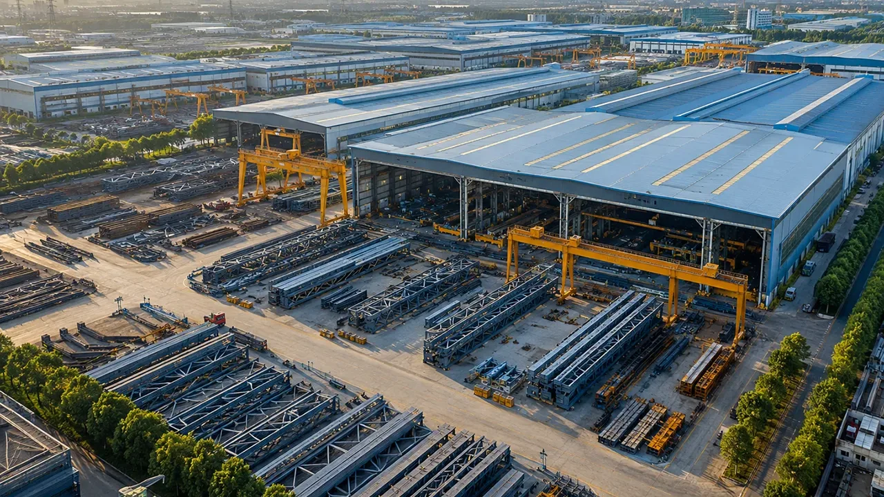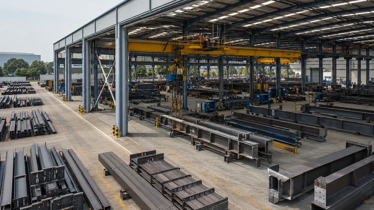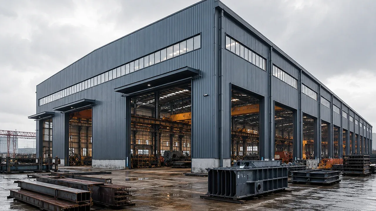
A steel frame load bearing structure is not just a collection of columns, beams, bolts, and plates. It is a coordinated structural system that gives every load a clear path from the point where it enters the building down to the foundation. In factories, warehouses, workshops, commercial halls, and multi-bay industrial buildings, this load path determines how safely and efficiently the building performs over time.
Every building receives loads from different directions. Roof panels carry dead load and weather load. Floors and platforms carry people, machines, stored materials, and maintenance activity. Walls receive wind pressure. Cranes and equipment may introduce repeated horizontal and vertical forces. A steel frame must collect these loads, transfer them through the right members, and deliver them safely into the ground.
This is why load-bearing design is more than member sizing. A strong beam is not enough if the connection is poorly detailed. A strong column is not enough if the base plate and anchor bolts do not match the foundation demand. A stable frame is not only about using heavy steel; it is about arranging beams, columns, bracing, connections, and foundations so the entire structure works as one system.
What Is a Steel Frame Load Bearing Structure?
A steel frame load bearing structure is a building system where the primary loads are carried by steel columns, beams, rafters, girders, bracing, and engineered connections. Instead of relying on load-bearing masonry walls or random partitions, the building uses a planned steel skeleton to support vertical and lateral forces.
In this type of structure, each major member has a defined role. Beams collect loads from roof or floor systems and transfer those loads horizontally. Columns carry forces downward. Connections allow forces to move from one member to another. Bracing or moment-resisting elements help control sideways movement. Foundations receive the final forces and distribute them into the soil.
For broader technical context, structural steel refers to steel materials shaped and used for load-bearing construction in buildings, bridges, towers, and other engineered structures. In a steel frame building, those members must be organized with a clear structural logic so the building can resist both daily service loads and extreme environmental actions.
The Basic Load-Bearing Logic
The basic logic is simple: loads must travel through a predictable path. A roof load may start on the roof sheeting, move into purlins, pass into rafters or primary beams, transfer into columns, and finally reach the foundation. A floor load may move through slab or decking, then into secondary beams, primary beams, columns, and base connections. A wind load may move through wall cladding, girts, bracing lines, columns, base plates, and anchor bolts.
If that path is clear, the building becomes easier to calculate, fabricate, erect, inspect, and maintain. If the path is unclear, forces may concentrate in unintended members. This can lead to excessive deflection, cracked cladding, misaligned doors, overstressed bolts, or costly site modifications. In industrial buildings, where cranes, equipment platforms, and suspended services may add complex loading, clear load-bearing logic becomes even more important.
Why Steel Frames Are Used for Load-Bearing Systems
Steel is widely used for load-bearing frames because it offers high strength, predictable fabrication, and flexible span arrangements. A steel frame can create wide open areas with fewer interior obstructions, which is valuable for warehouses, factories, logistics buildings, and commercial spaces that need flexible floor use.
Steel members can also be fabricated off-site with controlled cutting, drilling, welding, surface preparation, and trial fitting. Once delivered to site, columns, beams, rafters, bracing, and secondary members can be erected in a planned sequence. This makes steel framing practical not only for structural performance, but also for construction speed and future modification.
Another advantage is adaptability. If the frame has a clear grid and documented connection logic, future changes such as adding a mezzanine, extending a bay, opening a wall, or installing equipment supports can be evaluated more systematically. The structure still needs engineering review, but a well-organized frame gives owners a better starting point than a building where load-bearing responsibility is hidden inside walls or poorly documented elements.
Understanding Load Path in Steel Frame Buildings
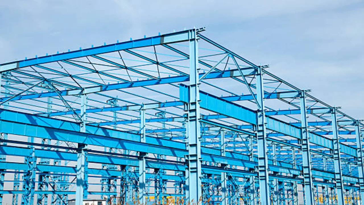
Load path is the route a force follows through a structure. In a steel frame building, this route should never be accidental. Each load should move from the point where it is applied to the members designed to resist it, then through connections, columns, base plates, anchor bolts, and foundations.
This concept is especially important in a steel frame load bearing structure because different parts of the building may carry different types of force at the same time. Roof members may carry gravity loads. Wall frames may collect wind pressure. Bracing may transfer lateral forces. Columns may carry axial compression while also resisting bending from wind, crane movement, or frame action.
Why Load Path Matters
A clear load path reduces uncertainty. Engineers can design each member for the forces it is expected to carry. Fabricators can prepare correct plates, holes, welds, and splices. Site crews can understand which members must be installed first and how the frame should be stabilized during erection.
When load path planning is weak, problems often appear during fabrication or construction. Bolt holes may not align. Bracing may conflict with openings. Base plates may not match anchor bolt positions. Connections may need field changes. In more serious cases, the building may experience serviceability issues after completion, such as excessive sway, roof deflection, door misalignment, or cladding movement.
Good load path planning also helps future modification. If the building owner wants to add equipment, extend the frame, or install a suspended system later, engineers need to understand how existing loads already move through the structure. A clear load path makes that review easier and safer.
Primary and Secondary Load Paths
Steel frame buildings usually include both primary and secondary load paths. The primary frame includes major load-bearing members such as columns, rafters, girders, primary beams, crane beams, and main bracing lines. These members carry the major structural responsibility and transfer large forces toward the foundation.
Secondary members include purlins, girts, joists, floor beams, roof sheeting supports, wall framing, and smaller connection elements. These members may look less important, but they are often the first parts of the building to receive loads. A roof panel load usually reaches a purlin before it reaches a rafter. A wall cladding load usually reaches a girt before it reaches a column or bracing line.
Stability elements form another important part of the load path. Diagonal bracing, roof bracing, wall bracing, rigid connections, and diaphragms help the frame resist movement. Without these elements, a frame may support vertical gravity loads but still perform poorly under lateral force.
How Vertical Loads Move Through Columns and Beams
Vertical load transfer is the easiest load path to visualize because gravity pulls downward. However, the actual path inside a steel frame can involve several stages. Loads rarely move directly from the roof or floor into the foundation. They usually pass through multiple members before reaching the ground.
Roof Loads and Floor Loads
Roof loads may include roof panels, insulation, purlins, ceiling systems, suspended utilities, rain, snow in applicable regions, maintenance workers, solar panels, or rooftop equipment. These loads are first collected by secondary roof members, then transferred into rafters, trusses, girders, or primary beams. From there, the forces move into columns and base connections.
Floor loads follow a similar logic. A mezzanine floor, service platform, or production floor may carry workers, machines, stored materials, maintenance tools, or equipment loads. The slab or decking transfers these forces to secondary beams, then to primary beams or girders, then to columns. If the floor supports concentrated equipment, local reinforcement or dedicated support beams may be required.
In industrial buildings, concentrated loads often matter more than general floor loading. A heavy machine, crane runway, service platform, pipe rack, or suspended conveyor may introduce forces that are much higher in one location than elsewhere. These loads must be identified early so the frame can be designed with proper local support.
Beam Action in Load Transfer
Beams carry loads horizontally across a span. When a beam receives load from a roof, floor, or secondary member, it bends. The upper and lower parts of the beam experience different internal forces, while the beam also develops shear near its supports. The longer the span or the heavier the load, the more carefully the beam must be designed for strength and deflection.
Deflection is important because a beam can be strong enough not to fail but still move too much for practical building use. Excessive deflection can affect roof drainage, ceiling systems, cladding alignment, equipment operation, platform comfort, or door performance. In industrial facilities, beam deflection may also affect crane runway alignment or service equipment clearance.
Beam design therefore involves more than choosing a steel section that can resist bending. Engineers also review span length, support condition, load type, serviceability limits, connection behavior, and construction sequence. A beam that performs well structurally must also fit the building’s usable space.
Column Action in Load Transfer
Columns carry forces downward into the foundation. In a simple vertical load case, the column mainly carries axial compression. In real buildings, however, columns may also experience bending, shear, uplift, crane-related forces, or lateral load effects. This makes column design especially important in industrial and commercial steel frames.
Column spacing also affects how the building can be used. Wide column spacing can create open space for storage, production, vehicles, or machinery, but it may require larger beams or rafters. Closer column spacing may reduce member size, but it can interfere with workflow, equipment layout, or future changes. The right column grid must balance structural efficiency with building function.
The base of the column is equally important. Forces from the column must pass through the base plate, grout, anchor bolts, and foundation. If the base connection is poorly coordinated, the column may be strong on paper but difficult to install or unable to transfer force cleanly into the foundation.
Connections: The Hidden Part of Load Transfer
Connections are often less visible than beams and columns, but they control how the frame behaves. A connection determines whether a beam transfers mainly shear, whether it can also transfer moment, how bracing forces enter the frame, and how erection tolerances are handled on site.
Beam-to-Column Connections
Beam-to-column connections can be simple or rigid depending on the structural requirement. A simple shear connection is typically designed to transfer vertical reaction while allowing some rotation. A moment connection is designed to transfer bending moment and restrict rotation between the beam and column. These two connection types do not behave the same way, so they should not be treated as interchangeable.
Common connection details may include end plates, fin plates, seat angles, bolted webs, welded flanges, stiffeners, continuity plates, and splice plates. The correct choice depends on the load demand, frame system, fabrication method, erection sequence, and inspection requirement.
Why Connection Detailing Affects Real Performance
A strong steel member can perform poorly if the connection is not detailed correctly. Bolt diameter, hole alignment, plate thickness, weld size, edge distance, access for tightening, and erection tolerance all influence performance. In fabrication, shop drawings must translate engineering intent into real components that can be cut, drilled, welded, coated, delivered, and assembled accurately.
Connection detailing also affects site productivity. If bolt holes do not align, if plates clash with other members, or if the installation sequence is unclear, the project may face field modification and delay. This is why a good steel frame design must consider not only structural calculation, but also constructability.
Lateral Loads in a Steel Frame Load Bearing Structure
A steel frame load bearing structure must resist more than vertical gravity loads. Buildings also face lateral forces that push the frame sideways. These forces may come from wind, seismic movement, crane operation, equipment vibration, vehicle impact, or repeated industrial activity. If lateral loads are not controlled properly, the building may experience excessive sway, connection stress, cladding damage, door misalignment, or long-term serviceability problems.
In many industrial buildings, lateral design is just as important as vertical load transfer. A warehouse with long wall surfaces may receive high wind pressure. A factory with overhead cranes may experience horizontal surge forces along crane runway lines. A multi-bay production building may need bracing arranged carefully so lateral movement does not interfere with machinery alignment, wall systems, or roof performance.
Wind, Seismic, Crane, and Operational Forces
Wind loads act on walls and roofs, then move through cladding, girts, roof systems, bracing, columns, and foundations. The taller or wider the building, the more important this load path becomes. Large industrial buildings with high eaves, long side walls, or lightweight cladding need careful lateral design because wind pressure can create significant horizontal force.
Seismic forces behave differently. They are dynamic and can move the building repeatedly in different directions. In seismic regions, the frame must resist force while also maintaining ductility and predictable behavior. This may require specific bracing details, moment connections, stronger columns, or special connection inspection.
Industrial operation can also create lateral demand. Crane movement may introduce horizontal surge and braking forces. Heavy equipment may cause vibration. Vehicles may create impact risk near loading zones. These actions should not be ignored because they affect how the frame behaves during real building use.
Bracing and Moment Frames
Lateral loads are commonly resisted by bracing systems, moment frames, roof diaphragms, wall systems, or a combination of these elements. Diagonal bracing is efficient because it creates a triangulated load path. Roof bracing helps distribute horizontal force across the roof plane. Wall bracing transfers force downward to columns, base connections, and foundations.
Moment frames work differently. Instead of relying mainly on diagonal members, they resist lateral movement through rigid beam-to-column connections. This can be useful when diagonal bracing would block doors, dock openings, glass façades, crane access, or workflow. However, moment frames usually require more demanding connection design, closer fabrication control, and careful inspection.
The best lateral system depends on the building layout. If the project has available wall bays where bracing will not block access, braced frames may be the most economical solution. If the building needs open façades or uninterrupted interior space, moment frames may be justified. In many industrial buildings, engineers use a hybrid approach to balance structural efficiency with operational needs.
Common Steel Frame Systems Used for Load-Bearing Buildings
Different steel buildings use different frame systems depending on span, height, loading, layout, and future expansion requirements. A small warehouse, a heavy workshop, a multi-story commercial building, and a crane-supported factory may all use steel, but the load-bearing logic can be very different.
| Frame System | Load-Bearing Role | Best Use | Design Concern |
|---|---|---|---|
| Portal steel frame | Transfers roof loads through rafters and columns | Warehouses, workshops, single-story industrial buildings | Wind load, eave height, bracing layout |
| Braced steel frame | Uses diagonal members to resist lateral loads | Factories, storage buildings, utility structures | Bracing must not block openings or workflow |
| Moment frame | Uses rigid beam-column connections to resist sway | Commercial façades, open interiors, entry zones | Connection complexity and drift control |
| Multi-story steel frame | Transfers floor and roof loads through beams and columns | Office, commercial, mixed-use, industrial platforms | Column alignment, floor vibration, lateral stability |
Portal Frames for Single-Story Industrial Buildings
Portal frames are commonly used in single-story warehouses, workshops, logistics buildings, and simple factories because they provide wide usable space with repeated frame bays. In this system, rafters and columns work together to support the roof and transfer loads toward the foundation. The frame can be efficient for buildings that need open interiors, fast erection, and practical roof support.
For many single-story warehouses and workshops, a Portal Steel Frame Structure is often selected because it combines roof support, column action, and lateral stability in a repeatable industrial layout. It is especially useful where the building needs clear span, simple geometry, and predictable expansion logic.
Even so, portal frames still require careful design. Wind load, roof slope, eave height, base connection behavior, bracing layout, crane requirements, and serviceability limits all affect performance. A portal frame may look simple, but its load-bearing behavior depends on how rafters, columns, haunches, bracing, and foundations work together.
Braced Steel Frames for Strong Stability
Braced steel frames use diagonal steel members to resist lateral loads. They are efficient because bracing creates a direct path for horizontal force. Instead of making every beam and column larger, engineers can place steel where it provides the most lateral stiffness.
The main challenge is coordination. Bracing must not block dock doors, production routes, machine access, window openings, façade zones, or future expansion points. If bracing is planned early, it can provide excellent stability with reasonable steel weight. If it is added late, it may solve a structural problem while creating an operational problem.
Moment Frames for Open Layouts
Moment frames are useful where diagonal bracing would interfere with building function. This can happen near entry areas, large doors, retail façades, glass walls, crane access zones, or flexible interior spaces. In a moment frame, the beam-column connection is designed to resist rotation and transfer bending moment.
This approach preserves openness, but it usually increases connection complexity. Moment connections may require thicker plates, stronger welds, stiffeners, continuity plates, closer inspection, and more precise fabrication. They are valuable when open space is a priority, but they should be selected for a clear reason rather than used by default.
Foundation and Base Connection Role in Load Transfer
All loads eventually reach the foundation. No matter how strong the beams, columns, or bracing are, the load path is incomplete unless the base connection and foundation can receive the forces safely. This is why foundation coordination must happen early in a steel frame project.
Base Plates and Anchor Bolts
Column forces move into the foundation through base plates, grout, anchor bolts, and concrete. These components must handle compression, shear, uplift, and sometimes bending or overturning effects. A column that carries crane loads, lateral loads, or moment effects may require a stronger base detail than a column carrying simple gravity load.
Anchor bolt layout is especially important during erection. If anchor bolts are misplaced, if the base plate holes do not match, or if the foundation elevation is wrong, the steel frame may be delayed before erection can properly begin. These problems are costly because they appear at the point where site work and fabrication must meet accurately.
Why Foundation Coordination Must Start Early
Foundation design should reflect the real frame behavior. Bracing can introduce uplift and shear at the base. Moment frames can introduce bending effects. Crane-supported frames may create repeated forces and higher column reactions. Equipment platforms may add concentrated loads in selected areas.
If these forces are not communicated clearly, the foundation may be undersized or poorly detailed. A strong upper frame with weak foundation coordination is not a complete load-bearing system. The steel frame, base connection, anchor bolts, and concrete foundation must be designed as one continuous load path.
Design Mistakes That Weaken Load-Bearing Performance
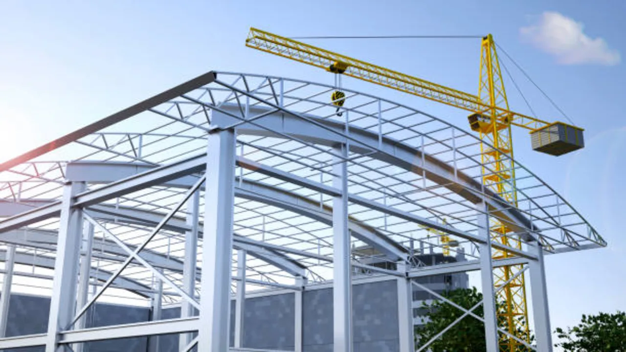
Even a well-sized steel frame can perform poorly if the design process overlooks how the system works in practice. Many load-bearing problems come not from weak steel members, but from poor coordination between engineering, fabrication, erection, and building operation.
Treating the Frame as Separate Members
A steel frame should not be designed as isolated pieces. Beams, columns, connections, bracing, base plates, and foundations must work together. If each member is considered separately without understanding the complete path of force, the design may miss important interactions.
For example, a beam may be strong enough for bending, but its connection may not transfer the required reaction. A brace may be strong enough in tension, but its gusset plate may be poorly detailed. A column may be sized correctly, but its base connection may not handle uplift or shear. Load-bearing performance depends on the whole system.
Ignoring Deflection and Serviceability
Strength is not the only requirement. A building can be strong enough to avoid collapse but still move too much for practical use. Excessive deflection or sway can affect cladding, doors, cranes, partitions, equipment alignment, roof drainage, and user comfort.
In industrial buildings, serviceability is often critical. Crane runway alignment, production equipment clearance, suspended service routes, and wall panel movement may all depend on limiting frame movement. Engineers must check not only ultimate strength, but also how the structure behaves under normal service conditions.
Late Changes to Equipment or Crane Loads
Crane beams, heavy machines, mezzanines, pipe racks, suspended conveyors, and service platforms should be identified early. If these loads are added after the main frame has already been designed, the project may need expensive reinforcement, connection redesign, or foundation changes.
Late changes are especially risky because they often affect more than one member. A new equipment load may require a stronger beam, a larger column, a new base plate, additional bracing, and foundation review. Early coordination avoids this chain reaction.
Poor Shop Drawing and Erection Coordination
Shop drawings translate engineering design into real fabricated steel. Bolt holes, connection plates, stiffeners, splice locations, erection marks, base plates, and bracing details must match the design intent. If this stage is weak, the site may face misalignment, missing parts, unclear erection sequence, or field modification.
Erection planning also matters. Some frames need temporary bracing during installation before the permanent stability system is complete. If the erection sequence is not understood, the frame may be difficult or unsafe to assemble. A load-bearing system must work not only after completion, but also during construction.
How to Evaluate a Steel Frame Load Bearing Structure for a Project
Before choosing a steel frame load bearing structure, project owners should evaluate the building as a complete structural and operational system. The best frame is not always the heaviest or the widest. It is the frame that gives the building a clear load path, practical layout, efficient fabrication, and long-term adaptability.
- Building function: Define whether the project is a warehouse, factory, workshop, commercial hall, logistics building, or multi-story facility.
- Span and clear height: Match the frame with storage, machinery, vehicles, cranes, platforms, and service routes.
- Column grid: Review whether column positions support or interrupt the actual building operation.
- Roof and floor loads: Identify roofing, floor use, maintenance loads, suspended services, and platform loads.
- Crane or equipment loads: Check whether heavy loads require special beams, columns, bracing, or foundations.
- Lateral load demand: Review wind, seismic, crane surge, equipment vibration, and operational impact.
- Connection type: Confirm whether the building needs simple shear connections, moment connections, bracing connections, or special base details.
- Bracing layout: Make sure bracing supports stability without blocking doors, workflow, dock areas, or future expansion.
- Foundation condition: Coordinate base plates, anchor bolts, soil conditions, uplift, shear, and compression forces.
- Future expansion plan: Consider whether additional bays, mezzanines, openings, or equipment upgrades may be needed later.
- Erection access: Review crane access, delivery sequence, temporary bracing needs, and site assembly conditions.
Conclusion: Strong Load Transfer Starts With Clear Structural Logic
A steel frame load bearing structure works best when every part of the frame supports a clear structural purpose. Beams collect and transfer loads. Columns carry forces downward. Connections allow forces to move between members. Bracing and moment systems stabilize the frame against lateral movement. Base plates, anchor bolts, and foundations complete the load path.
Good steel frame design is not only about selecting strong members. It is about creating a coordinated system that can be calculated, fabricated, erected, inspected, maintained, and modified with confidence. When load transfer is planned from the beginning, the building becomes safer, more efficient, easier to construct, and better prepared for future use.