Steel roof trusses and industrial frames depend on carefully designed joints to transfer forces between individual structural members. Chords, diagonals, vertical members, beams, columns, and braces may each have sufficient strength, but the complete structure cannot perform reliably unless those members are connected through a clear and continuous load path.
Gusset plate connections are among the most widely used methods for joining multiple steel members at a common structural point. A gusset plate creates a practical surface for bolts, welds, or a combination of both, allowing forces to move from one member into the surrounding frame.
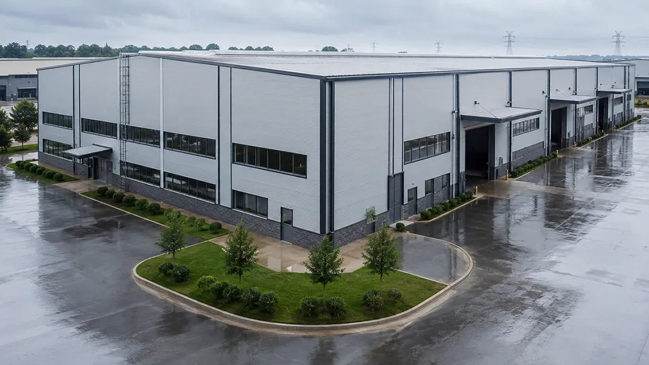
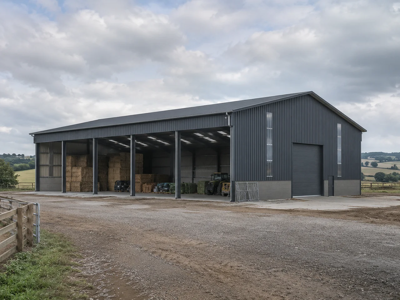
These connections are commonly found in warehouses, factories, workshops, hangars, long-span roof systems, pipe racks, crane-supporting frames, and equipment-support structures. Their performance depends on plate thickness, geometry, member alignment, bolt or weld configuration, fabrication accuracy, installation quality, and the forces acting on the joint.
What Are Gusset Plate Connections?
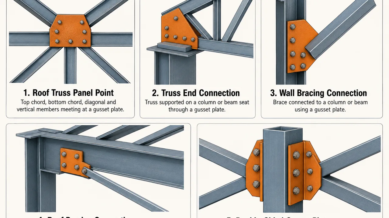
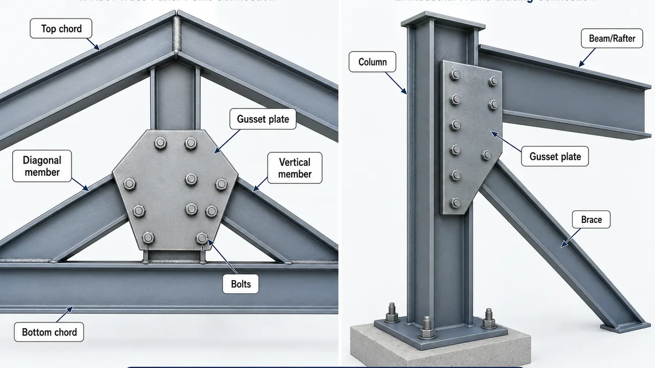
A gusset plate is a flat structural steel plate used to connect two or more members. In a roof truss, the plate may connect a top chord, bottom chord, diagonal member, and vertical member at the same panel point. In an industrial frame, it may connect a wall brace or roof brace to a beam, column, rafter, or truss.
Directly connecting several members to one another is often difficult because their centerlines, angles, and section shapes do not provide enough space for bolts or welds. A gusset plate solves this problem by creating a shared connection area through which the member forces can be collected and redistributed.
A typical gusset plate connection may include:
- A structural steel gusset plate
- Top or bottom truss chords
- Diagonal or vertical web members
- Beams, columns, rafters, or braces
- Structural bolts
- Welds
- Stiffeners or connection angles where required
Unlike a simple cover plate or non-structural attachment, a load-carrying gusset plate must be designed to resist the actual forces passing through the joint.
How Gusset Plate Connections Transfer Forces
Axial Force Transfer
Truss members and bracing members are primarily intended to carry axial tension or compression. When a member reaches a gusset plate, its force passes through bolts or welds into the plate. The plate then distributes that force to the other connected members.
For example, a diagonal roof-truss member may transfer compression into a gusset plate at the top chord. The plate then delivers that force into the chord and any adjacent web members. In a wall-bracing system, a diagonal brace may transfer wind force through the plate into a column or beam.
A reliable connection maintains a continuous path from the applied load through the joint and into the supporting structure.
Behavior Under Tension
When a connected member pulls on the plate, the connection must resist several possible limit states. The plate may yield across its gross section, fracture through its reduced net section, or fail through block shear around a bolt group.
Bolts must resist shear and bearing, while welds must provide sufficient effective length and throat thickness. Bolt holes, plate edges, and weld terminations must be arranged to avoid excessive stress concentration.
Behavior Under Compression
When a connected member pushes against the plate, buckling becomes an important design consideration. A thin gusset plate with a large unsupported region may deform out of plane before developing its expected resistance.
Compression performance depends on plate thickness, unsupported length, edge restraint, member angle, and the location of the force path. In highly loaded joints, the designer may reduce the unsupported projection, increase the plate thickness, or provide additional restraint.
Eccentricity and Secondary Bending
Ideally, the centerlines of the connected members should intersect near a common work point. When the member centerlines do not align, the force may enter the plate eccentrically and introduce secondary bending.
This additional bending can increase stresses in the gusset plate, bolts, welds, chord, beam web, column flange, or supporting connection. Unavoidable offsets should therefore be included in the structural analysis rather than ignored during detailing.
Gusset Plate Connections in Steel Roof Trusses
Top Chord Connections
The top chord of a roof truss commonly carries compression under gravity loading. At a panel point, the top chord may connect with one or more diagonal or vertical members through a gusset plate.
The connection must account for the roof slope, member angles, chord continuity, and available space around purlins or roof bracing. Plate geometry should allow the connected member centerlines to meet as closely as practical without interfering with secondary steelwork.
Bottom Chord Connections
Bottom chords often carry tensile forces. Bolt holes can reduce the net section of the chord or connecting plate, making net-section fracture an important check.
Where the bottom chord is spliced, the gusset plate may transfer force between chord segments while also connecting diagonal or vertical web members. Straight force paths help reduce secondary bending and uneven stress distribution.
Web Member Connections
Diagonal and vertical web members transfer forces between the top and bottom chords. Several members may meet at a single panel point, creating a compact and heavily loaded connection zone.
The gusset plate must provide enough room for bolts or welds without creating an overcrowded layout. Excessively dense bolt groups can make fabrication, installation, tightening, and inspection difficult.
Truss End Connections
At the end of a roof truss, the connection transfers the truss reaction into a supporting column, beam, bracket, or bearing seat. This region may carry substantial shear, bearing, and axial forces.
The end gusset plate must coordinate with the support detail and allow practical erection tolerances. The connection should also provide sufficient access for bolt tightening, welding, coating, and inspection.
Ridge and Apex Connections
At the roof ridge, sloping top chords meet at the apex. The connection must maintain geometric symmetry and transfer chord and web-member forces without excessive local deformation.
Space for bolts and welds may be limited, particularly in steep roof trusses. Accurate cutting and assembly are important to maintain the specified roof geometry.
Gusset Plate Connections in Industrial Frames
Wall Bracing Connections
Industrial buildings commonly use X-bracing, single diagonal bracing, or other wall-bracing arrangements to resist longitudinal wind and seismic forces. Gusset plates connect the braces to beams, columns, or beam-column joints.
The connection must resist brace tension and compression while maintaining alignment with the theoretical work point of the bracing system.
Roof Bracing Connections
Roof bracing stabilizes the building longitudinally and transfers horizontal forces between roof trusses, rafters, columns, and wall-bracing systems.
Connections must be coordinated with purlins, roof panels, service openings, and other roof components. Poor coordination can create installation conflicts or force the brace away from its intended alignment.
Crane-Supporting Industrial Frames
Crane-supporting structures may experience repeated loading, impact, vibration, and changes in force direction. These effects can make fatigue and connection stiffness important considerations.
Gusset plates in crane-supporting frames require controlled detailing, accurate fabrication, suitable weld profiles, and reliable inspection. Abrupt force paths or poor-quality weld terminations can increase fatigue demand.
Pipe Racks and Equipment-Support Frames
Pipe racks and equipment structures may carry vertical loads, wind, seismic forces, vibration, and pipe expansion forces. Their joints often have limited space because several braces, beams, pipes, and access platforms occupy the same area.
Compact gusset plate geometry must therefore be balanced with installation access, maintenance requirements, and structural capacity.
Common Types of Gusset Plate Connections
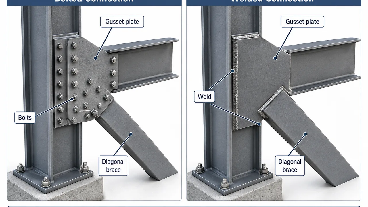
Bolted Gusset Plate Connections
Bolted connections are commonly used where trusses or braces are assembled on site. Plates and members can be drilled in the factory, transported separately, and joined during erection.
Advantages include faster field assembly, reduced field welding, easier inspection, and the possibility of limited adjustment or replacement. However, bolt holes reduce the net section, and the connection must provide adequate spacing, edge distance, bearing resistance, and bolt capacity.
Welded Gusset Plate Connections
Welded connections create a compact and continuous load-transfer path. They are especially suitable for controlled shop fabrication, where welding conditions, fit-up, heat input, and inspection can be managed consistently.
Potential disadvantages include residual stress, heat distortion, limited field access, and greater difficulty when modifications are required.
Combined Bolted and Welded Connections
A common prefabricated-steel arrangement is to weld the gusset plate to the main frame in the factory and bolt the truss member or brace to the plate on site.
This method combines controlled shop welding with fast field installation. It can also simplify transportation and allow easier alignment during erection.
Single-Sided and Double-Sided Gusset Plates
A single-sided gusset plate connects to one face of a member and may introduce eccentricity if the force path is not aligned with the member centerline. It is generally simpler to fabricate but may create single-shear bolt behavior.
Double-sided plates can improve force symmetry and place bolts in double shear. However, they require more material, greater fabrication accuracy, and additional assembly work.
Bolted vs Welded Gusset Plate Connections
| Consideration | Bolted Connection | Welded Connection |
|---|---|---|
| Factory preparation | Requires accurate drilling or punching | Requires controlled fit-up and welding |
| Site installation | Generally faster | May require qualified field welding |
| Adjustability | Allows limited erection adjustment | More difficult to modify |
| Inspection | Bolt layout is visible | Weld quality must be verified |
| Net-section loss | Reduced by bolt holes | No bolt-hole reduction |
| Heat distortion | Not normally significant | Must be controlled |
| Maintenance | Individual components may be easier to replace | Repairs may require cutting and rewelding |
| Typical application | Field-assembled trusses and braces | Shop-fabricated joints |
Key Design Considerations
Plate Thickness
Plate thickness must be selected based on tension, compression, shear, bending, block shear, and buckling requirements. The unsupported plate dimensions and connection force level are especially important for compression checks.
Using an unnecessarily thick plate is not always beneficial. It increases material use, welding demand, heat input, weight, and fabrication difficulty.
Plate Shape and Dimensions
The plate must provide sufficient length and width for bolts or welds while fitting within the available joint area. Member angles, edge geometry, installation access, and interference with surrounding steelwork should all be considered.
Sharp internal corners and abrupt changes in plate shape should be avoided where they may create stress concentrations.
Effective Width and Force Distribution
Member force spreads outward as it passes through the gusset plate. Designers evaluate an effective section, often associated with the Whitmore width concept, to determine the portion of the plate participating in force transfer.
This effective width is used when checking yielding, tensile rupture, and compression buckling.
Bolt Arrangement
Bolt design should consider diameter, grade, quantity, hole size, pitch, gauge, edge distance, end distance, shear, bearing, and slip resistance where required.
The layout should distribute forces efficiently while remaining practical for drilling, installation, tightening, and inspection.
Weld Arrangement
Weld size and effective length must match the actual force direction. Unbalanced weld arrangements can introduce rotation and secondary stresses into the plate.
Weld terminations, access, sequencing, and distortion control should be coordinated with the fabrication process.
Member Work Point Alignment
Aligning the member centerlines near a common work point helps reduce eccentric moments. The work-point geometry shown in structural calculations should match the dimensions used in fabrication drawings.
Installation Clearance
The design should provide space for bolt tightening, welding, inspection, coating application, and future maintenance. Gusset plates must also be coordinated with purlins, cladding, pipes, ducts, cable trays, and equipment.
Gusset Plate vs Other Steel Connection Types
Gusset plates are particularly suitable for truss joints, brace connections, and locations where several structural members meet. Other connection types may be more appropriate for simpler or more direct load-transfer conditions.
- End plates are commonly used for beam-to-column or beam-to-beam connections.
- Splice plates connect separate segments of the same structural member.
- Cleat angles and fin plates are frequently used for simple beam connections.
- Direct welded joints may be used where geometry and fabrication conditions allow.
Gusset Plate vs End-Plate Connection
Gusset plates are typically used to connect diagonal braces, truss chords, and web members where forces enter the joint from different directions. End plates are more commonly attached to the end of a beam and then bolted to a column, another beam, or a supporting member.
The two connection types differ in geometry, force direction, member arrangement, fabrication, and typical application. A detailed comparison of gusset plate vs end-plate connection can help designers determine which system better suits a specific structural joint.
Common Failure Modes
Gross-Section Yielding
The plate may undergo permanent deformation when its effective gross area is insufficient for the applied tensile force.
Net-Section Fracture
Bolt holes reduce the available steel area. An inadequate net section may fracture under tension.
Block Shear
Block shear combines tension and shear failure around a bolt group. Bolt layout and plate edge distances strongly influence this failure mode.
Bolt Shear and Bearing Failure
Insufficient bolt capacity may cause bolt shear, while excessive contact pressure can deform the plate around the holes.
Weld Failure
Welds may fail because of inadequate size, insufficient length, defects, poor orientation, or unsuitable termination details.
Gusset Plate Buckling
A thin plate with a long unsupported region may buckle under compression. Insufficient restraint and eccentric loading can increase the risk.
Member Tear-Out or Edge Failure
Insufficient edge distance may allow the steel between a bolt hole and the plate edge to tear away.
Fatigue and Repeated Loading
Crane loads, machinery vibration, cyclic wind, and repeated operational forces can initiate fatigue cracking. Smooth load paths and controlled weld details are particularly important in these applications.
Fabrication Process
Engineering and Shop Detailing
The fabrication process begins with determining the forces entering the joint. Engineers then select the plate material, thickness, geometry, bolt arrangement, weld configuration, and supporting details.
Shop drawings should clearly show plate dimensions, steel grade, hole locations, bolt specifications, weld sizes, member angles, work points, and surface-protection requirements.
Plate Cutting and Hole Preparation
Plates may be produced using CNC plasma cutting, laser cutting, flame cutting, or another suitable process. Bolt holes may be drilled or punched according to the required tolerance and plate thickness.
Accurate templates and dimensional control help ensure that field-assembled members fit correctly.
Shop Welding
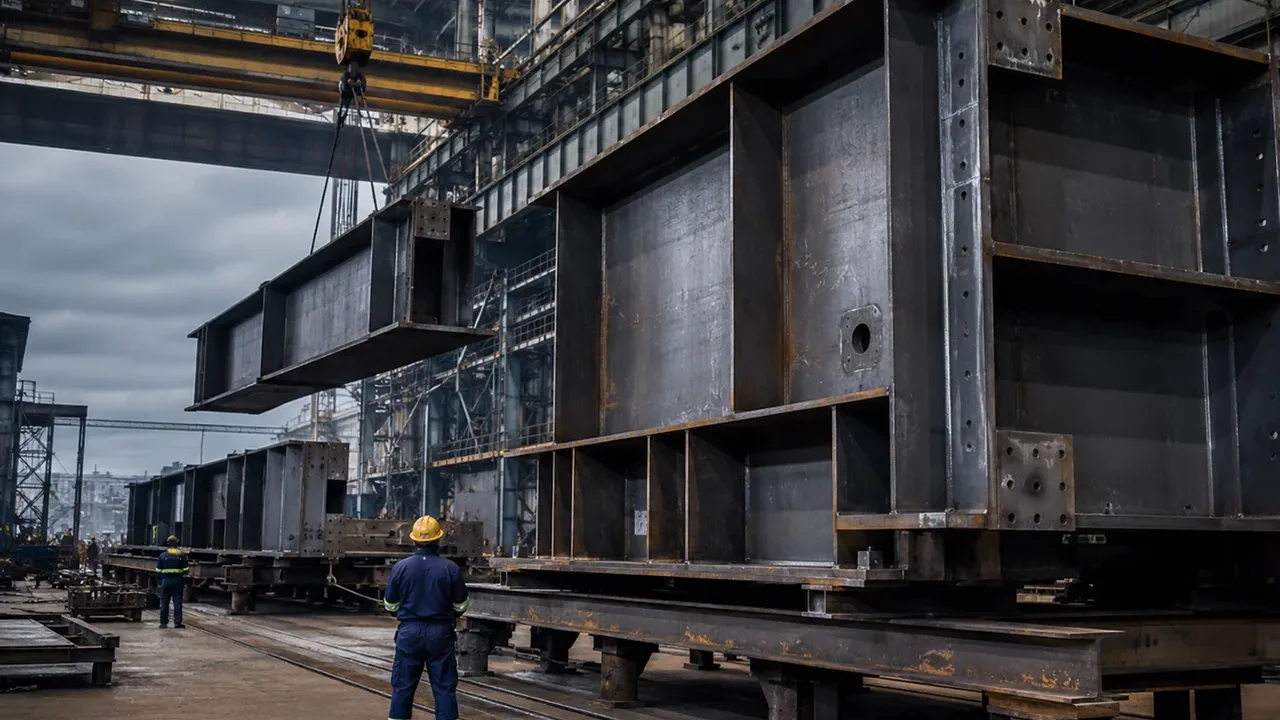
Shop welding requires controlled fit-up, sequence, heat input, and distortion. XTD Steel Structure coordinates connection detailing with steel fabrication to help maintain dimensional accuracy before components are shipped to the construction site.
Surface Protection
Depending on the project environment, gusset plates may receive blast cleaning, protective paint, galvanizing, or another corrosion-protection system. Connection interfaces and damaged coating areas should receive appropriate treatment after assembly.
Site Installation Process
Site installation normally includes the following steps:
- Position the truss or frame members.
- Install temporary bracing and supports.
- Align bolt holes and theoretical work points.
- Insert and tighten the structural bolts.
- Complete field welding where required.
- Verify truss geometry, frame alignment, and plumbness.
- Inspect the completed connection.
- Remove temporary supports only after structural stability is confirmed.
Inspection and Quality Control
Material Verification
- Confirm plate grade and material certificates.
- Verify plate thickness.
- Inspect the material for surface defects or corrosion.
Dimensional Inspection
- Check plate length and width.
- Verify hole locations and edge distances.
- Confirm member angles and work-point alignment.
- Inspect connection fit-up.
Bolt Inspection
- Confirm bolt grade, diameter, and quantity.
- Check washers and installation direction.
- Verify the required tightening method.
- Inspect contact surfaces where slip resistance is required.
Weld Inspection
- Verify weld size and length.
- Inspect for cracks, porosity, undercut, and incomplete fusion.
- Perform non-destructive testing where required.
Final Alignment Inspection
- Check overall truss geometry.
- Confirm brace straightness.
- Inspect the plate for unintended deformation.
- Verify beam and column alignment.
Common Design and Detailing Mistakes
- Using standard plate shapes without checking actual forces
- Selecting plate thickness without checking compression buckling
- Misaligning member centerlines
- Providing insufficient bolt edge distance
- Overcrowding the bolt group
- Using unbalanced weld layouts
- Ignoring access for tightening or welding
- Failing to coordinate with purlins or cladding
- Ignoring fatigue in crane or machinery-supporting frames
- Providing inadequate corrosion protection
- Failing to coordinate structural and fabrication drawings
How to Select the Right Gusset Plate Connection
Connection selection should begin by identifying all forces entering the joint. The designer should determine whether each member carries tension, compression, or both and then evaluate the available connection space.
The selected solution should:
- Provide sufficient plate strength and buckling resistance
- Provide adequate bolt or weld capacity
- Maintain a direct load-transfer path
- Limit unnecessary eccentricity
- Allow practical fabrication and erection
- Provide access for inspection and maintenance
- Account for corrosion, fatigue, and seismic requirements
Final connection calculations should be coordinated with qualified structural engineers and the actual fabrication and erection methods.
Frequently Asked Questions
What Is the Main Purpose of a Gusset Plate Connection?
A gusset plate transfers forces between truss chords, diagonal members, vertical members, braces, beams, and columns. It also provides a practical surface for bolts and welds.
Are Gusset Plate Connections Better Bolted or Welded?
Neither method is universally better. The most suitable choice depends on fabrication conditions, site access, force level, inspection requirements, erection speed, and maintenance needs.
How Thick Should a Truss Gusset Plate Be?
The required thickness depends on member forces, steel strength, plate geometry, unsupported length, buckling resistance, and the bolt or weld arrangement. It should be determined through project-specific calculations.
Can One Gusset Plate Connect Several Truss Members?
Yes. Top chords, bottom chords, diagonals, and vertical members commonly meet at one truss panel point and connect through the same plate.
Why Do Gusset Plates Buckle?
Buckling may occur when a compression force acts through a thin plate with a large unsupported region. Eccentric loading and insufficient restraint can increase the risk.
Are Gusset Plates Used in Industrial Buildings?
Yes. They are widely used in roof trusses, wall bracing, roof bracing, crane-supporting frames, pipe racks, and equipment-support structures.
Conclusion
Gusset plate connections are essential components of steel roof trusses and industrial frames. They transfer axial forces, join multiple structural members, and help maintain the stability of the complete steel system.
Reliable connection performance requires more than selecting a plate thickness. Plate geometry, member alignment, bolt or weld design, buckling resistance, fabrication accuracy, installation access, and quality control must be considered together.
By treating the connection as part of the complete structural load path, designers and fabricators can reduce local failure risks and help ensure that roof trusses and industrial frames perform safely throughout their service life.