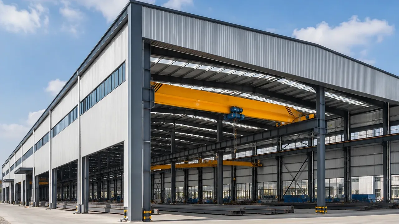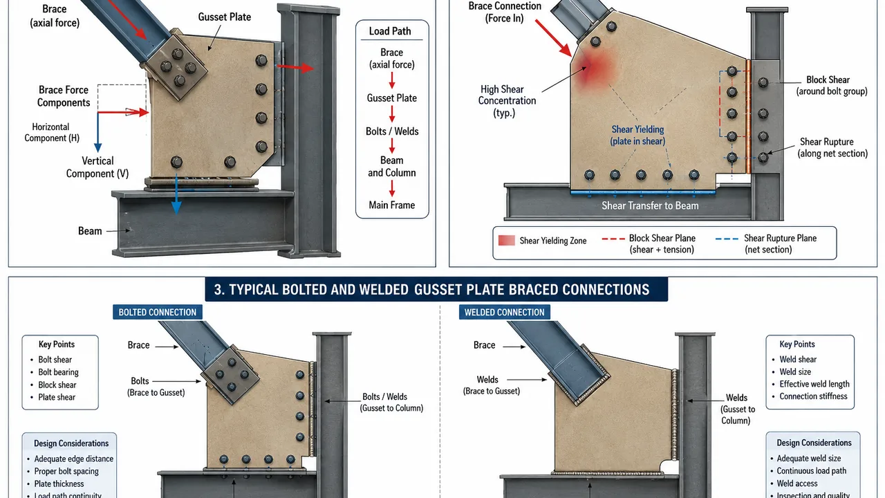
A diagonal brace may appear to carry a simple axial force, but the connection at its end has a more complicated job. Once the brace force reaches the gusset plate, it must be transferred through the plate, bolts or welds, and ultimately into the beam, column, or supporting frame. During this process, horizontal and vertical force components can create significant shear loads in gusset plate connections.
Understanding this load path is essential because a connection can be limited by more than the strength of the brace itself. Gusset plate shear yielding, shear rupture, block shear, bolt shear, bearing around bolt holes, weld strength, plate stability, and the capacity of connected members may all influence the final design.
A reliable connection therefore requires engineers to evaluate the complete force-transfer system rather than treating the gusset plate as an isolated steel plate.
What Are Shear Loads in Gusset Plate Connections?
Shear load in a gusset plate is an in-plane force that tends to make one part of the plate slide relative to another. In braced frames, this force commonly develops as the axial force in a diagonal brace is resolved into horizontal and vertical components at the connection.
For example, a diagonal brace connected near a beam-column intersection may deliver both a horizontal component toward the column and a vertical component toward the beam. The gusset plate, welds, bolts, beam, and column must provide a continuous path for those forces.
The exact distribution depends on the brace angle, connection geometry, support conditions, and the way the gusset is attached to surrounding members.
How Brace Forces Create Shear
A brace primarily carries axial tension or compression. However, because most braces are inclined, their axial force acts at an angle to the beam and column.
That inclined force can be resolved into:
- A horizontal component
- A vertical component
- Resulting forces transferred through the gusset plate
The connection geometry determines how these components reach the surrounding frame. If the brace work point, beam centerline, column centerline, and actual connection interfaces are not well coordinated, eccentricity may also introduce additional local effects.
This is why checking only the axial capacity of the brace does not provide a complete picture of connection behavior.
Shear Load vs Axial Load in a Gusset Plate
Axial force acts primarily along the direction of the brace, while gusset plate shear develops as that force is transferred across the connection.
A single gusset may therefore experience several actions at the same time:
- Tension or compression from the brace
- In-plane shear
- Local bearing around fasteners
- Local bending caused by eccentric force transfer
- Compression-related stability effects
The connection must be checked for the relevant combination of these actions rather than assuming that only one force type controls.
How Shear Loads Travel Through a Braced Frame Connection
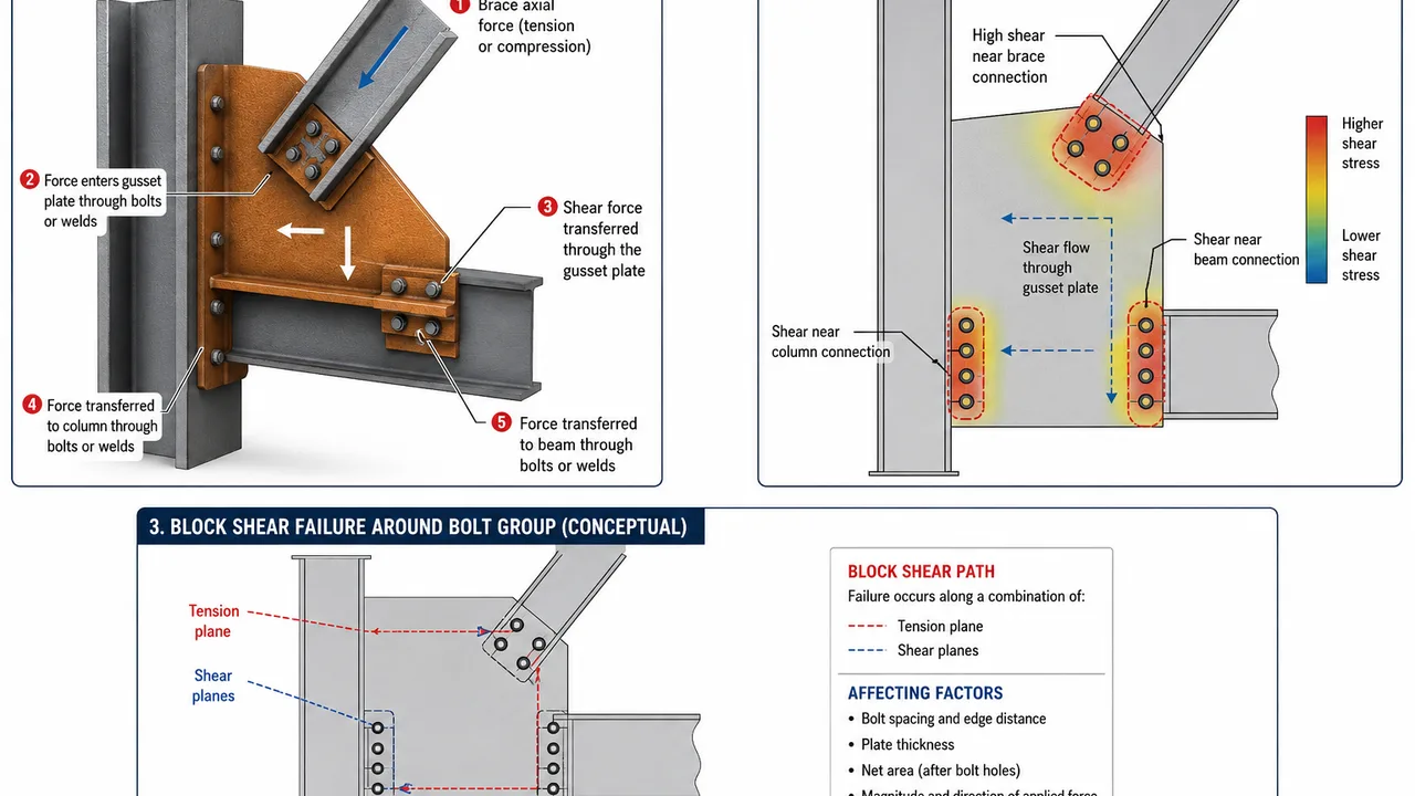
A clear load path is one of the most important requirements in connection design. For a typical braced frame, the force may travel through the following sequence:
Brace → brace-to-gusset connection → gusset plate → beam/column interface → main structural frame
Every component in this path must have sufficient capacity and appropriate detailing.
From the Brace Into the Gusset Plate
The brace may be attached to the gusset using bolts, welds, or a combination of connection components depending on the brace section and project requirements.
In a bolted connection, force passes from the brace into the bolts and then into the gusset plate through bearing and shear. Bolt spacing, hole arrangement, edge distance, plate thickness, and the number of fasteners all affect performance.
In a welded connection, force enters the plate through the weld group. Weld length, orientation, throat size, accessibility, and the relationship between the weld line and applied force must be coordinated.
Eccentricity between the brace centerline and the actual connection plane can create additional effects that should be included in the connection analysis.
From the Gusset Plate Into the Beam and Column
After entering the plate, the brace force must continue into the surrounding frame. A typical gusset plate braced connection may transfer forces through welded or bolted interfaces to both the beam and column.
The plate should not simply be checked for local strength near the brace. Engineers must also verify whether the force can safely leave the plate and enter the connected structural members.
Connection layout, weld length, bolt groups, gusset geometry, and brace work-point location influence how the load is divided between the beam and column.
Where Shear Stress Develops in the Gusset Plate
Shear stress is not necessarily distributed uniformly over the entire gusset plate. Critical regions usually occur where forces enter or leave the plate and around geometric discontinuities.
Shear Near the Brace Connection
Near the brace-to-gusset interface, a relatively concentrated brace force must spread into a wider plate area.
Critical details may include:
- Bolt groups
- Weld lines
- Plate edges
- Changes in plate width
- Areas close to bolt holes
A thin plate or short load-transfer region can increase local demand even when the overall gusset dimensions appear adequate.
Shear Near Beam and Column Interfaces
Shear also develops where the gusset attaches to the beam or column. Welded edges and bolted connection regions must transfer the required forces without local yielding, rupture, or excessive deformation.
A longer interface can provide more area for force transfer, but connection effectiveness still depends on geometry and load distribution. Increasing weld length or adding bolts does not automatically solve an unfavorable load path.
Influence of Gusset Plate Geometry
Gusset geometry directly affects both strength and constructability.
Important variables include:
- Plate thickness
- Plate width and depth
- Brace angle
- Length of the connected edges
- Free-edge dimensions
- Location of bolt groups
- Tapered or rectangular plate shape
A larger gusset may provide more connection space, but unnecessary plate size can increase weight, fabrication work, interference with adjacent components, and compression stability concerns.
Shear Yielding of the Gusset Plate
Shear yielding occurs when the shear demand in the gross plate area reaches the yielding resistance of the steel.
This limit state is important because the gusset must maintain an adequate gross area along the force-transfer path. Plate thickness, effective shear length, steel grade, and connection geometry all influence available resistance.
Shear yielding should be distinguished from fracture. Yielding involves significant inelastic deformation of the steel, while rupture involves loss of material continuity.
Factors That Increase Shear Yielding Demand
Conditions that can make shear yielding more critical include:
- Higher brace design forces
- Thin gusset plates
- Short force-transfer regions
- Narrow plate geometry
- Highly concentrated connection forces
- Unfavorable brace and connection alignment
Increasing plate thickness may improve shear capacity, but the complete connection should still be checked before assuming that a thicker plate solves every limit state.
Shear Rupture and Block Shear
Yielding is not the only possible plate failure. Connections must also be evaluated for fracture through reduced or net sections.
Shear Rupture
Shear rupture can occur along a net shear plane where bolt holes or other discontinuities reduce the effective steel area.
This makes bolt-hole layout important. Two gussets with the same overall dimensions and thickness can have different rupture resistance if their hole patterns create different net sections.
Adequate spacing, edge distance, and connection geometry therefore contribute directly to the strength of bolted gusset plates.
Block Shear Around Bolt Groups
Block shear is a connection limit state involving a block of material that can separate along a combination of shear and tension planes.
It is commonly associated with bolted connections where the bolt arrangement creates a potential failure path between the bolt group and the plate edge.
Factors affecting block shear include:
- Number of bolts
- Bolt spacing
- Edge distance
- End distance
- Plate thickness
- Net area after bolt-hole deductions
A bolt group may have sufficient fastener strength while the surrounding plate remains vulnerable to block shear, so both must be checked.
Bolt Shear in Gusset Plate Connections
In a bolted connection, the fasteners themselves form part of the shear load path.
Bolt capacity depends on the fastener specification, connection configuration, number of bolts, shear planes, and applicable structural design requirements. The arrangement should also distribute force in a practical manner instead of relying on an unnecessarily congested group.
Increasing the number of bolts can increase connection capacity, but it also enlarges the joint and can affect plate net area, fabrication time, erection access, and block shear paths.
Bolt Bearing and Hole Deformation
The plate around each bolt hole is also subjected to bearing.
This means bolt strength alone cannot determine whether the connection is adequate. The gusset plate or connected brace may experience local deformation, bearing failure, or tear-out around the holes.
Plate thickness, bolt diameter, edge distance, spacing, and load direction should therefore be coordinated as part of the same design check.
Weld Shear in Gusset Plate Connections
Welded gusset connections transfer force through the effective weld area between the plate and connected member.
How Welds Transfer Shear
The required weld arrangement depends on the direction and magnitude of the applied connection force.
Important considerations include:
- Effective weld length
- Weld size
- Weld orientation
- Connection geometry
- Access for fabrication
- Inspection requirements
The weld should provide a continuous and understandable path between the gusset plate and the supporting member.
Why Longer Welds Are Not Automatically Better
Simply extending a weld does not guarantee efficient force distribution.
Long weld groups may still experience nonuniform demand when the applied force is eccentric to the connection. Plate stiffness, weld arrangement, geometry, and the location where the load enters the connection all affect how forces are distributed.
Efficient detailing therefore requires more than adding weld length.
Combined Shear, Tension, and Compression
Real bracing connections rarely experience pure shear. The plate often responds to shear together with tension, compression, or local bending.
Shear Plus Tension
When the brace is in tension, forces spread from the brace connection into the gusset and then into the surrounding frame.
The engineer may need to evaluate multiple limit states, including:
- Plate yielding
- Net-section rupture
- Block shear
- Bolt or weld resistance
- Connected-member capacity
The critical limit state depends on the actual plate and connection geometry.
Shear Plus Compression
When the brace is in compression, strength alone is not enough. Gusset plate stability can also become important.
Plate thickness, unsupported dimensions, free-edge geometry, brace connection length, and surrounding restraint influence compression behavior.
A very thick plate is not automatically the best solution. Connection stiffness and gusset geometry must also permit the structural behavior expected by the bracing system.
How Bracing Configuration Changes Shear Demand
The arrangement of the braces changes how forces reach the gusset plate and supporting frame.
Single Diagonal Bracing
A single diagonal brace usually provides a relatively direct force path between two frame joints. Its axial force produces horizontal and vertical components at each connection.
The gusset arrangement should transfer those components while maintaining practical fabrication and erection clearances.
X-Bracing
X-bracing uses diagonals crossing within the same bay. Depending on the structural system and load direction, individual braces may experience tension, compression, or force reversal.
The connection design must reflect the forces assigned to each brace and the actual way the members intersect or pass one another.
Chevron and Inverted-V Bracing
Chevron and inverted-V arrangements connect braces near a common point on a beam.
Because two brace forces meet in this region, differences between their forces can create significant unbalanced demand on the beam and its connections.
The gusset plates, beam connection, brace forces, and frame behavior must therefore be evaluated together rather than as independent components.
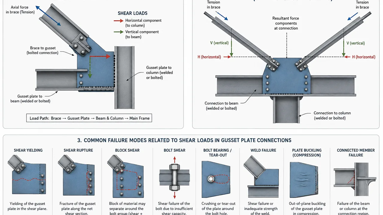
Common Failure Modes Related to Shear Loads
The following table summarizes several limit states that may need consideration when designing connections subjected to shear.
| Failure Mode | Typical Location | Main Design Concern |
|---|---|---|
| Shear yielding | Gusset plate | Gross shear area and plate strength |
| Shear rupture | Gusset plate | Net shear area |
| Block shear | Around bolt groups | Combined tension and shear failure path |
| Bolt shear | Fasteners | Bolt strength and number of shear planes |
| Bolt bearing or tear-out | Plate around bolt holes | Plate thickness, spacing, and edge distance |
| Weld failure | Welded interfaces | Weld strength, length, and force direction |
| Plate instability | Compression region | Plate slenderness and restraint |
| Connected-member failure | Beam or column interface | Completion of the structural load path |
Practical Design Checks for Shear Loads in Gusset Plate Connections
A practical evaluation of shear loads in gusset plate connections should follow the load from the brace all the way into the main frame.
A typical workflow includes:
- Determine the governing brace design force.
- Resolve the brace force into the required connection components.
- Establish the intended load path.
- Determine how forces are transferred to the beam and column.
- Check gusset plate shear yielding.
- Check shear rupture and block shear where applicable.
- Check bolt or weld resistance.
- Check bearing, tear-out, and other local plate effects.
- Evaluate gusset stability when compression is present.
- Check the connected beam, column, and supporting components.
- Confirm that the detail can be fabricated, erected, and inspected as intended.
Actual design should always follow the governing project specification and applicable structural code.
Common Design Mistakes
Several connection problems begin with an incomplete understanding of how force moves through the joint.
Common mistakes include:
- Treating brace force as pure axial force throughout the connection
- Ignoring horizontal and vertical force components
- Checking the plate but not the bolts or welds
- Overlooking block shear around bolt groups
- Providing insufficient bolt edge distance
- Assuming shear stress is perfectly uniform
- Ignoring connection eccentricity
- Neglecting gusset stability under compression
- Adding field holes without structural review
- Designing each connection component independently instead of checking the complete load path
Avoiding these mistakes generally produces a connection that is easier to understand, fabricate, inspect, and erect.
Gusset Plate Detailing for Reliable Shear Transfer
Good detailing supports both structural performance and practical fabrication.
The designer should coordinate:
- Adequate plate thickness
- Practical bolt spacing and edge distances
- Sufficient weld access
- Clear force-transfer geometry
- Brace alignment with the intended work point
- Space for tightening bolts and inspecting welds
- Avoidance of unnecessary connection congestion
- Clear identification of shop and field connections
- Access for protective coatings and future inspection
Connection details should also account for erection sequence. A theoretically strong connection can still create problems if bolts cannot be installed, welds cannot be reached, or adjacent structural members interfere with field assembly.
Shear Load Design as Part of the Complete Braced Frame Connection
The most important principle in evaluating shear loads in gusset plate connections is continuity of the load path. Brace strength alone does not determine connection performance, and increasing gusset plate thickness does not automatically solve every possible limit state.
The brace, gusset plate, bolts, welds, beam, column, and connection geometry must work together as one structural system. Shear yielding, rupture, block shear, fastener capacity, weld resistance, local bearing, stability, and connected-member strength all need to be considered where applicable.
A well-designed braced frame connection balances structural strength with clear force transfer, fabrication efficiency, erection access, and long-term reliability. When these requirements are coordinated from the beginning, the gusset plate can perform its intended role efficiently without introducing unnecessary complexity into the steel structure.