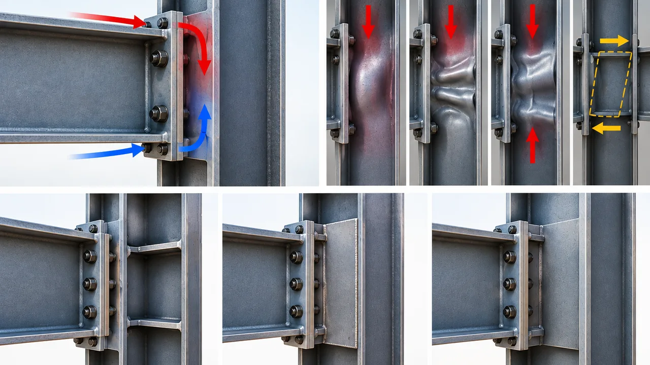
A bolted end-plate moment connection can have adequate bolts, a sufficiently thick end plate, and properly designed welds while still developing a critical weakness in the supporting column. The reason is simple: connection forces do not stop at the bolts. They must continue through the column flange and into the column web. When the transferred compression becomes large relative to the local web capacity, yielding, crippling, compression buckling, or excessive panel-zone deformation can govern the connection.
Understanding web buckling around bolted end-plate connections therefore requires more than checking one isolated component. Engineers need to follow the complete load path from the beam through the end plate and into the supporting column, then identify the specific local limit state that could control.
This distinction is especially important for deep beams, heavily loaded moment connections, relatively thin column webs, and connections in which beams frame into both sides of a column. A connection that appears robust from the outside may still require transverse stiffeners, doubler plates, or a larger column section to provide an adequate force-transfer mechanism.
Why Web Buckling Develops Around End-Plate Connections
The bending moment delivered by a beam is commonly represented through a force couple acting near the beam flanges. One flange region transfers tension while the opposite region transfers compression. In an end-plate connection, these forces pass through the end plate, bolts, bearing surfaces, welds, column flange, and ultimately the column web.
On the tension side, much of the design attention naturally goes toward bolt tension, prying action, end-plate bending, and column flange bending. On the compression side, however, the force must also enter the supporting member through a relatively concentrated region. This creates significant local stresses in the column flange and web.
If the web is comparatively thin or the connection force is large, the local response may become more important than the nominal axial or flexural stress in the column as a whole. This is one reason web buckling around bolted end-plate connections cannot be evaluated only by reviewing the global column utilization ratio.
How Moment Is Transferred Through the Connection
The simplified load path can be viewed as:
Beam → beam flange and web → welded end plate → bolts/contact region → column flange → column web → column section.
The actual force distribution is more complex because end-plate flexibility, bolt-row location, prying effects, column flange deformation, continuity plates, and panel-zone behavior interact with each other.
Nevertheless, tracing this load path is useful because every element must have sufficient strength and stiffness for the connection to perform as intended. Increasing bolt capacity, for example, does not automatically improve a deficient column web.
Concentrated Compression at the Column Web
The compression flange of the beam introduces a concentrated force into the supporting column. The column flange spreads part of this load before it reaches the web, but the web still experiences a localized demand around the connection.
The magnitude and distribution of this force depend on several variables, including beam moment, beam depth, column flange thickness, column web thickness, end-plate configuration, and whether another beam frames into the opposite side of the column.
As the concentrated force increases, the web may progress from elastic deformation toward local yielding or instability. Determining which behavior governs is an essential part of connection design.
Why Slender Column Webs Are More Vulnerable
Web thickness has a direct influence on local resistance. A relatively slender web provides less material to resist localized compression and is also more susceptible to instability.
Clear web depth, steel strength, column flange stiffness, connection geometry, and restraint from surrounding components also affect behavior. This means two columns with similar overall flexural capacity can have significantly different resistance to concentrated connection forces.
Web Buckling Is Not a Single Failure Mode
The phrase web buckling is frequently used as a general description for visible web deformation. In structural design, however, several distinct limit states need to be separated. Properly identifying the governing mechanism is critical because the resistance calculation and reinforcement strategy are not necessarily the same.
The concentrated-force provisions of the AISC Specification for Structural Steel Buildings distinguish local web and flange limit states rather than treating all localized deformation as one generic failure.
Web Local Yielding
Web local yielding occurs when concentrated force causes the material in the web near the loaded flange to reach its yield strength over the effective load-distribution region.
This is fundamentally a strength condition rather than an instability condition. A stockier web may yield locally before it develops the buckled-wave deformation associated with local crippling.
The distinction matters because a design described casually as web buckling around bolted end-plate connections may actually be governed by web local yielding.
Web Local Crippling
Web local crippling is associated with concentrated compressive force and localized deformation of the web adjacent to the loaded flange. Compared with local yielding, it is more strongly associated with instability of a relatively slender web.
The resulting deformation can appear as localized buckled or crumpled regions close to the compression load path.
When local crippling resistance is insufficient, appropriately designed transverse stiffeners or other web reinforcement may be required to provide a more reliable path for the concentrated force.
Web Compression Buckling
Web compression buckling is another distinct condition. It becomes relevant when compressive forces act through both flanges in a manner that places the web in a compression field susceptible to buckling.
This should not automatically be assumed for every end-plate connection. Engineers need to evaluate the actual loading arrangement, including whether connections or other concentrated forces occur on opposite sides of the column.
The geometry and loading condition therefore determine whether web compression buckling is a meaningful design check.
Web Panel-Zone Shear
Moment transfer through a beam-to-column joint also creates significant shear in the column panel zone. Excessive panel-zone demand can produce substantial shear deformation or yielding even if the local concentrated-force checks are satisfactory.
Panel-zone shear and localized web buckling are related through the same connection region, but they are different limit states and should be evaluated separately.
Web Sidesway Buckling Is a Different Limit State
Web sidesway buckling is sometimes incorrectly grouped with the checks used for moment connections. Under the AISC concentrated-force provisions, web sidesway buckling addresses specific compression-bearing conditions and is not the corresponding check for a moment connection.
For this reason, engineers evaluating web buckling around bolted end-plate connections should avoid applying every web-buckling equation simply because the word “buckling” appears in its name. The correct limit state must match the actual force path and connection condition.
How End-Plate Geometry Affects Column Web Demand
In a bolted end-plate connection, bolt layout, end-plate stiffness, beam depth, column flange stiffness, and supporting-member geometry interact to determine how forces enter the column.
Changing one connection component can alter the behavior of several others.
Beam Depth and Flange Force
Beam moment is transferred through tension and compression forces separated by an internal lever arm. As a simplified concept, a larger lever arm can reduce the flange force required to transfer a given moment, while a smaller effective lever arm increases it.
Actual connection design must account for the detailed geometry rather than relying only on this simplified relationship, but the principle explains why beam depth is directly related to local connection demand.
End-Plate Thickness and Stiffness
A flexible end plate can deform under bolt tension and develop prying effects. A thicker plate generally changes this deformation pattern and can increase the force that other connection components are capable of transferring.
That does not mean thicker is always better for the supporting column. Strengthening the end plate and bolt group may shift the governing limit state into the column flange or column web.
Connection components should therefore be proportioned as part of a system.
Bolt Row Arrangement
The number and location of bolt rows influence how tension is distributed through the end plate. Extended end-plate configurations can place bolt rows outside the beam flanges, while other arrangements position them differently relative to the beam tension zone.
Bolt arrangement primarily affects the tension-side mechanism, but changes in overall connection strength and stiffness can also influence the demand ultimately transferred to the supporting column.
Column Flange Flexibility
Before force reaches the web, it passes through the column flange. A relatively flexible column flange can bend locally, while a stronger flange may transfer greater forces into the web before another limit state develops.
Column flange bending and column web resistance should consequently be checked together rather than treated as unrelated design questions.
Key Parameters Controlling Web Resistance
The likelihood of web buckling around bolted end-plate connections depends on the interaction of several geometric and loading variables.
| Parameter | Effect on Connection Behavior |
|---|---|
| Column web thickness | A thicker web generally increases resistance to local yielding, crippling, and instability. |
| Clear web depth | Influences web slenderness and the susceptibility of the web to instability. |
| Web yield strength | Affects available resistance for yielding-related limit states. |
| Beam flange force | Determines the concentrated tension or compression demand entering the column. |
| Column flange thickness | Affects local flange bending and the distribution of force into the web. |
| End-plate stiffness | Changes deformation, prying behavior, and connection force distribution. |
| Bolt arrangement | Influences tension-force distribution and overall connection stiffness. |
| Opposite-side framing | Can create double-concentrated forces and alter panel-zone demand. |
| Stiffeners or doubler plates | Provide additional strength or alternative load-transfer paths when the unreinforced web is inadequate. |
Step-by-Step Design Check for the Column Web
A practical evaluation should begin with connection forces and move progressively into the supporting column. This prevents an engineer from strengthening one connection component while overlooking another component that becomes critical afterward.
Step 1: Determine the Connection Forces
Establish the governing moment, shear, and axial force at the joint for the applicable load combinations. The beam moment can then be related to the tension and compression forces acting through the beam flange regions and connection components.
For seismic systems, connection forces may need to reflect expected material strength, probable beam moment, or other capacity-design requirements rather than only elastic analysis results.
Step 2: Trace the Concentrated Force Into the Column
Identify where the beam flange force reaches the column, the effective loaded region, and whether the force is applied close to a member end or within an interior region.
Also determine whether another beam or concentrated force acts on the opposite flange. This distinction can change the relevant web checks.
Step 3: Check Web Local Yielding
Evaluate the available strength of the web for local yielding under the concentrated force. This check addresses yielding of the web material near the load introduction region.
If available web strength is lower than required strength, reinforcement or a different column section may be necessary.
Step 4: Check Web Local Crippling
Where concentrated compression is present, evaluate web local crippling using the applicable specification provisions.
This check is particularly important when a thin web is paired with substantial concentrated compression. It should not be replaced by a generic slenderness check because the concentrated-force geometry is part of the resistance calculation.
Step 5: Evaluate Web Compression Buckling Where Applicable
Determine whether the loading arrangement creates the double-concentrated compression condition associated with web compression buckling.
The presence of beams on both sides of a column does not by itself mean this limit state automatically governs. The direction and magnitude of the forces must be considered.
Step 6: Check Panel-Zone Shear
Calculate the panel-zone demand generated by the beam-column moment transfer. In high-moment connections, the panel zone can become critical independently of web local yielding or crippling.
Panel-zone reinforcement may therefore be required even when the local concentrated-force checks pass.
Step 7: Compare Required and Available Strength
Apply the appropriate LRFD or ASD design format required by the project. The final connection should satisfy every applicable component and local-member limit state, not merely the bolt or end-plate calculation.
This systematic approach provides a much clearer assessment of web buckling around bolted end-plate connections than checking an isolated web slenderness ratio.
Warning Signs That the Column Web May Control
Certain combinations should prompt closer examination during preliminary connection design. A deep or high-strength beam framing into a lighter column can generate substantial local column demand. The same is true when the selected bolt group and end plate are capable of developing a moment close to the beam strength while the supporting column has a comparatively thin web.
Large moment demand, thin column webs, significant opposite-side framing, highly restrained joints, strong end plates, and heavy beam flange forces are all reasons to examine local column behavior early.
Doing so can prevent a late design change in which an apparently economical column requires extensive reinforcement after the connection calculations are completed.
Reinforcement Options for an Inadequate Column Web
When web buckling around bolted end-plate connections or another local column limit state governs, reinforcement should address the actual failure mechanism. Adding steel without identifying that mechanism can increase fabrication cost without providing the most efficient solution.
Transverse Stiffeners
Transverse stiffeners, sometimes referred to as continuity plates in beam-column moment connections, can provide a direct path for flange forces through the column.
Properly designed stiffeners reduce the demand that would otherwise have to spread through an unreinforced web. Their thickness, width, welds, fit-up, and alignment with the beam flange force are important parts of their performance.
Doubler Plates
Doubler plates strengthen the column web region and are commonly associated with increasing panel-zone capacity or addressing web deficiencies requiring broader reinforcement.
The plate must be detailed as part of the complete joint. Welding sequence, access, plate termination, interaction with continuity plates, and distortion control all affect fabrication.
Selecting a Larger Column
Reinforcing a light column is not always the lowest-cost solution. Multiple stiffeners and doubler plates introduce material, welding, inspection, fitting, and shop-handling requirements.
In some projects, selecting a heavier column with a thicker web or flange can eliminate several local deficiencies simultaneously and simplify fabrication.
Modifying Connection Geometry
Another option is to reconsider the beam-column combination or connection configuration. Changing beam size, end-plate geometry, column section, or load path can sometimes reduce reinforcement requirements.
The objective should be overall connection efficiency rather than maximizing the capacity of every individual component.
Stiffeners or Doubler Plates?
The appropriate reinforcement depends on the governing limit state.
| Connection Condition | Potential Design Response |
|---|---|
| Localized beam flange force exceeds web resistance | Transverse stiffener or continuity plate |
| Web local crippling controls | Appropriately detailed transverse stiffening or other local reinforcement |
| Applicable web compression buckling deficiency | Full-depth stiffening or another engineered web-strengthening solution |
| Panel-zone shear controls | Doubler plate, stronger column web, or alternative joint design |
| Several column-side limit states fail | Combined reinforcement or selection of a heavier column section |
| Reinforcement creates excessive fabrication complexity | Reconsider the original beam-column and connection selection |
A stiffener should not be selected simply because localized deformation is visible in an analysis model. The governing engineering limit state should first be established.
Fabrication Details Can Determine Whether Reinforcement Works
Connection calculations and fabrication details need to be coordinated. A stiffener that is structurally adequate on paper can still create problems if it conflicts with bolts, weak-axis framing, weld access, erection clearances, or other connection components.
Transverse stiffeners should align correctly with the intended flange-force path. Their welds need sufficient access and must transfer the required forces without introducing unnecessary fabrication difficulty.
Doubler plates require similar attention. Plate fit-up, weld termination, sequence, accessibility, and potential distortion should be considered before shop drawings are released.
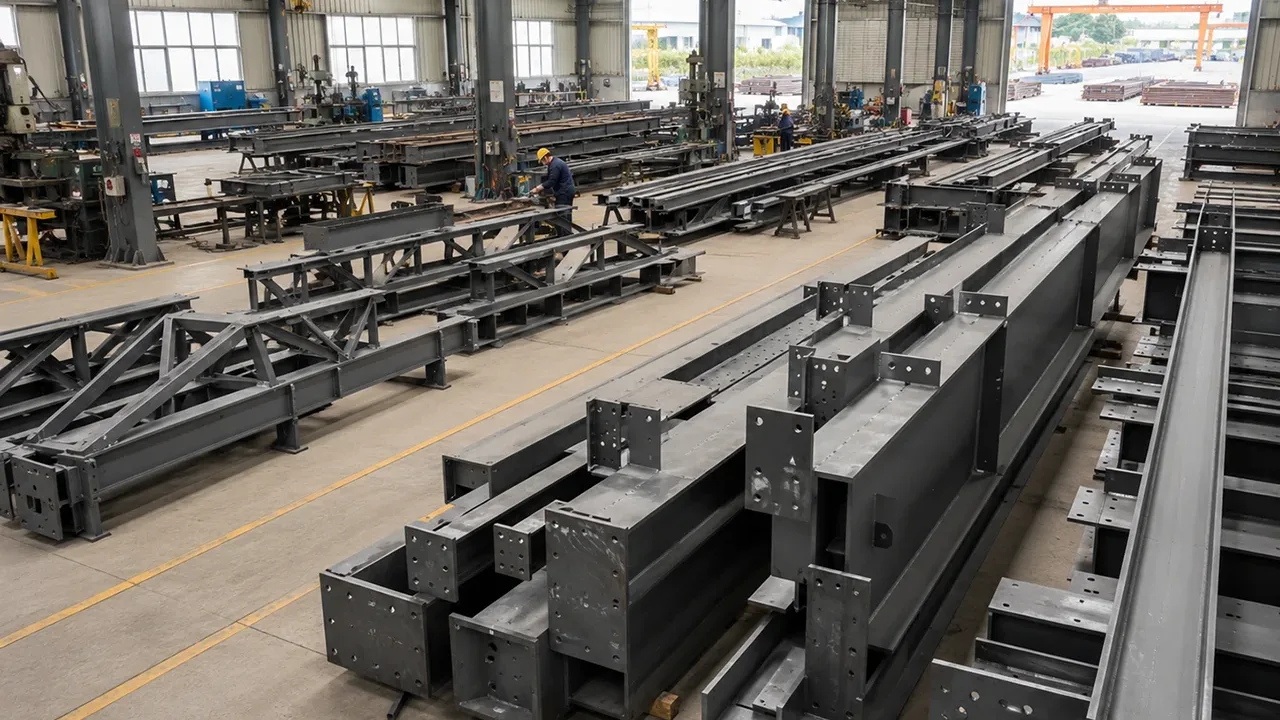
For fabricated steel projects, XTD Steel Structure coordinates connection detailing with member fabrication so reinforcement requirements can be reviewed together with welding access, assembly sequence, transportation constraints, and erection conditions. This is especially useful when a connection contains continuity plates, doubler plates, multiple bolt rows, or framing from several directions.
Web Checks in Seismic End-Plate Connections
Seismic moment connections require additional attention because the design objective can extend beyond resisting forces calculated from ordinary elastic load combinations.
ANSI/AISC 358 includes prequalified bolted unstiffened and stiffened extended end-plate moment connections for applicable special and intermediate moment-frame systems. These configurations are subject to specific geometric, material, detailing, and design requirements.
The intent of a prequalified seismic connection includes controlling where inelastic behavior develops. Consequently, bolts, end plates, welds, column components, panel zones, and reinforcement cannot be proportioned independently.
Engineers addressing web buckling around bolted end-plate connections in seismic frames should follow the applicable seismic provisions, prequalification requirements, and project-specific code edition rather than transferring a gravity or wind connection check directly into a seismic design.
Common Design Mistakes Around End-Plate Connections
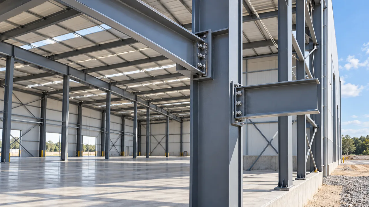
One recurring mistake is checking bolts and end-plate thickness thoroughly while assuming that a satisfactory column member automatically provides a satisfactory connection region. Global column strength and local concentrated-force resistance are different design questions.
Another mistake is describing every column-web problem as “web buckling.” Local yielding, local crippling, compression buckling, and panel-zone shear have different physical mechanisms and different design provisions.
The compression side of the joint can also receive less attention than the tension side. Bolt tension and prying action are highly visible connection-design issues, but the compression flange force still needs a complete path through the supporting member.
Over-reinforcement can be a problem as well. Adding continuity plates or doubler plates without determining the governing limit state increases welding, inspection, distortion risk, and fabrication time.
Finally, global structural-analysis software should not be assumed to complete every local connection check automatically. Connection component design and local supporting-member checks remain necessary unless the analysis method specifically models and verifies those behaviors.
A Practical Design Workflow
A reliable workflow begins by establishing the governing beam-column forces and selecting a preliminary end-plate configuration. The engineer can then check the bolt group, end plate, welds, column flange, and applicable column-web limit states before reviewing panel-zone behavior.
Where the column is inadequate, the next step is not automatically to add reinforcement. Compare transverse stiffeners, doubler plates, connection modifications, and heavier column sections from both structural and fabrication perspectives.
After the structural solution is selected, shop detailing should confirm bolt access, weld access, stiffener alignment, plate fit-up, fabrication sequence, and compatibility with framing entering the joint from other directions.
For complex steel structures, early coordination between the structural designer and fabricator can prevent connection reinforcement from becoming a late-stage production issue. XTD Steel Structure can incorporate approved connection details into fabrication planning so member geometry, stiffeners, plates, welds, and erection requirements are coordinated before delivery.
Frequently Asked Questions
What Causes Web Buckling Around Bolted End-Plate Connections?
Web buckling around bolted end-plate connections can develop when concentrated forces transferred from the beam and connection create demands that exceed the local resistance of the supporting column web. The specific governing mechanism may be web local crippling, applicable compression buckling, or another local limit state, so the actual force condition must be identified before selecting a design equation or reinforcement method.
Is Web Buckling the Same as Web Local Yielding?
No. Web local yielding is yielding of the web material within the concentrated-force region. Buckling or crippling involves instability and deformation of the web. Although the symptoms can occur in the same connection region, they are separate limit states.
Does a Thicker End Plate Prevent Column Web Buckling?
Not necessarily. A thicker end plate can increase end-plate strength and reduce some plate deformation, but the transferred force still has to enter the column. Strengthening the end plate may simply shift the governing condition to the column flange, web, bolts, welds, or panel zone.
When Are Column Web Stiffeners Required?
Stiffeners may be required when the unreinforced column cannot provide adequate strength for an applicable concentrated-force or connection limit state. The required configuration depends on the governing mechanism, connection geometry, and design standard.
Can a Doubler Plate Prevent Web Buckling?
A doubler plate can increase web-region strength and is particularly useful for certain panel-zone or web deficiencies. It should not be treated as a universal solution for every localized failure. Reinforcement needs to correspond to the actual limit state.
Does Web Sidesway Buckling Apply to End-Plate Moment Connections?
The web sidesway buckling provisions used for concentrated compression in bearing-type conditions are not the corresponding AISC limit-state check for moment connections. End-plate moment connections should instead be evaluated for the local column and panel-zone limit states applicable to their actual force transfer.
Should the Column Web Be Checked if the Bolts and End Plate Are Adequate?
Yes. Bolt capacity and end-plate capacity confirm only part of the connection load path. The column flange, column web, panel zone, welds, and any required reinforcement must also have adequate strength and detailing for the connection to perform as intended.