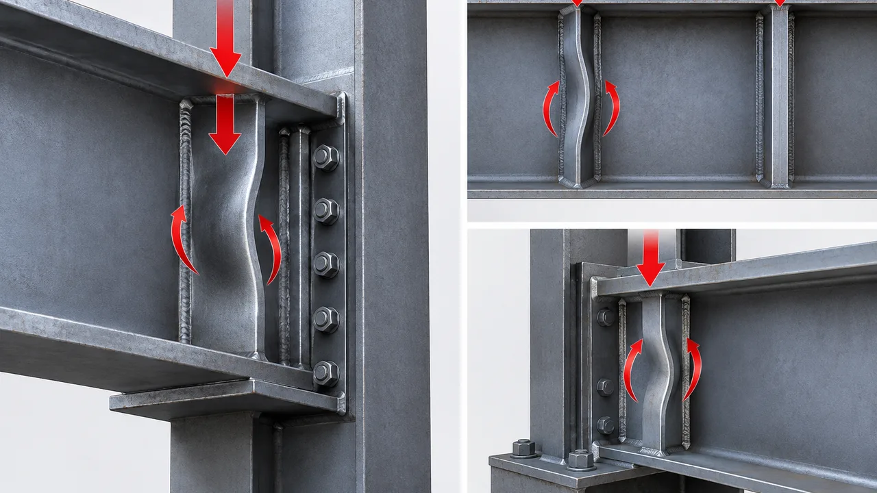
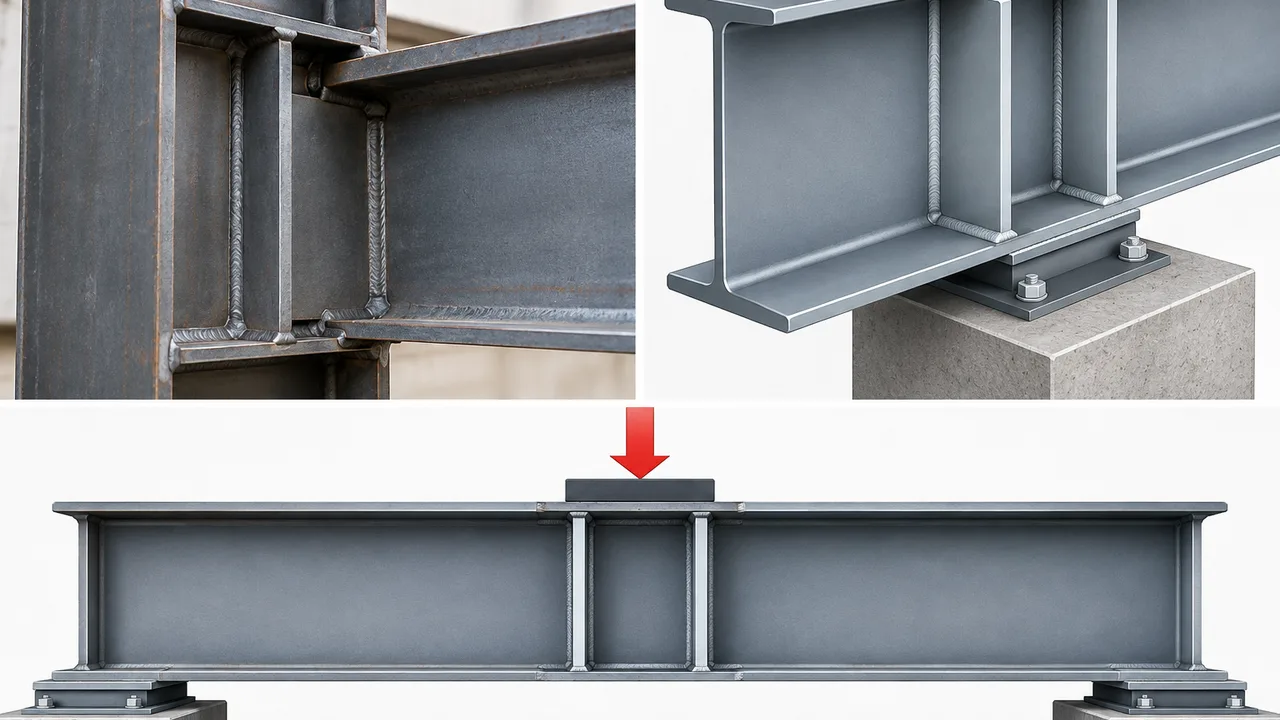
Stiffeners are frequently added to steel connections when a web, flange, support region, or concentrated load path needs more strength or stability than the main member can provide alone. They can help transfer beam reactions, reinforce bearing zones, support flange forces, and stabilize thin web panels. However, adding a stiffener does not automatically make a connection safe. If the plate is too slender, poorly restrained, misaligned with the applied force, or distorted during welding, stiffener buckling can become the governing failure mode.
This type of instability is especially important in beam-to-column connections, transfer girders, crane beams, industrial support structures, and other locations where concentrated compressive forces pass through relatively small areas. A connection may have adequate material strength and sufficiently strong welds while still losing capacity because the stiffener deforms out of plane before its full compressive resistance can be developed.
Preventing the problem requires more than increasing plate thickness. Engineers must consider the complete force path, plate slenderness, restraint conditions, weld details, fabrication tolerances, surrounding web behavior, and the way forces enter and leave the stiffened region.
What Is Stiffener Buckling?
A stiffener is generally a plate attached to the web or flange of a structural member to reinforce a local region. Depending on the connection, it may carry direct compression, improve web stability, distribute concentrated forces, or provide additional restraint to another component.
How Stiffeners Work in Steel Connections
In a typical steel connection, the stiffener works together with the surrounding web, flange, and welds rather than acting as an isolated plate. Compressive force may enter through a beam flange, bearing plate, bracket, crane rail support, equipment support, or another connected component. The stiffener then helps spread or transfer that force into the larger structural member.
Common functions include:
- transferring concentrated compression through a beam or column web;
- reinforcing support and bearing regions;
- supporting flange forces in moment connections;
- reducing deformation of slender web panels;
- improving the local stability of built-up girders;
- supporting crane, machinery, or industrial equipment reactions.
What Happens When a Stiffener Buckles?
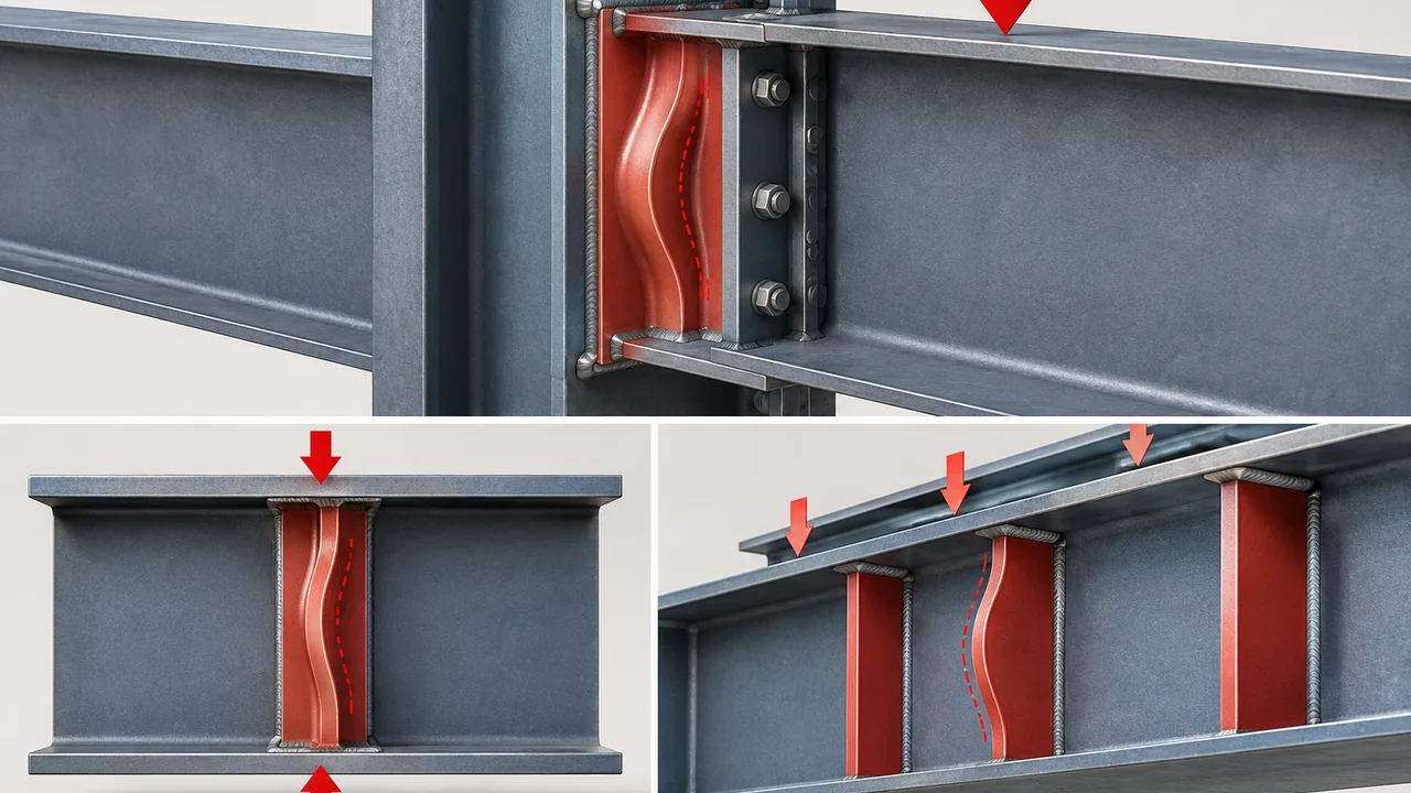
When a compression-loaded stiffener loses stability, the plate begins to deflect laterally or out of its original plane. Once this deformation becomes significant, the force distribution inside the connection changes. Part of the load may shift into the surrounding web, flange, welds, or adjacent reinforcement plates.
The result can include reduced connection stiffness, concentrated local stresses, increased web deformation, weld demand, and permanent distortion. In severe cases, instability can initiate a sequence of local failures even though the steel has not reached its nominal tensile or compressive material strength.
Stiffener Buckling vs Stiffener Yielding
Yielding and buckling are different limit states. Yielding occurs when stresses reach the material yield strength and permanent deformation develops. Buckling, by contrast, is a stability problem strongly influenced by geometry, slenderness, restraint, imperfections, and load alignment.
A thin stiffener may therefore lose stability before the plate material reaches yield. This is why replacing the plate with higher-strength steel does not necessarily solve the problem. If plate dimensions and restraint remain unchanged, higher yield strength may provide limited benefit when instability controls the design.
Where Stiffener Buckling Commonly Occurs
Beam-to-Column Connections
Moment connections can transfer substantial tension and compression through beam flanges into a column. Continuity plates or transverse stiffeners may be introduced to distribute these forces across the column section. If those plates are too slender or inadequately connected, local instability can develop under the compressive flange force.
Beam Web Bearing Zones
Large end reactions often create concentrated compression near supports. Stiffeners may be used to reinforce the beam web and create a more direct force path between the loaded flange and the support region. Their thickness, width, bearing condition, and connection to the web and flange all influence stability.
Crane Beams and Heavy Industrial Connections
Industrial structures can be particularly demanding because crane wheels, equipment supports, transfer brackets, and operating machinery may introduce large localized loads. Some loads are also repeated or dynamic. Stiffeners in these areas must therefore provide both adequate strength and reliable dimensional stability.
Transfer Girders and Heavy Load Connections
Transfer girders and built-up members can carry exceptionally high support reactions. Multiple stiffener plates may be required to deliver those forces into the web and flanges without excessive localized deformation. Small detailing errors can become important when force levels are high.
Main Causes of Stiffener Buckling
Excessive Stiffener Slenderness
Plate slenderness is one of the primary factors affecting stiffener buckling. A wide, thin plate is generally more susceptible to out-of-plane instability than a thicker plate with the same unsupported width. Designers therefore need to consider the plate width-to-thickness relationship rather than selecting thickness based only on compressive stress.
Insufficient Lateral Restraint
A stiffener that appears strong in cross-section may still perform poorly if its edges or ends are insufficiently restrained. Partial-depth stiffeners, plates with long unsupported edges, and details that do not engage the flange effectively may permit lateral deformation to develop earlier than expected.
High Concentrated Compression
Stiffeners located near reactions, flange force transfer zones, equipment supports, or crane connections can experience high compression over a relatively short length. If the actual load exceeds the assumed demand or enters the plate through a smaller effective area, the risk of instability increases.
Eccentric Load Transfer
Ideally, compressive force should pass through the stiffener in a clear and direct manner. In practice, connection geometry can introduce eccentricity. A load acting away from the stiffener plane produces bending in addition to compression, which can significantly increase out-of-plane deformation.
Poor Stiffener Geometry
Simply making a plate wider does not always improve performance. Additional width can increase the unsupported plate projection and therefore increase slenderness. Improper termination, inadequate contact with the flange, or a geometry that does not correspond with the actual force path may also reduce efficiency.
Welding-Induced Imperfections
Welding introduces heat, shrinkage, and residual stresses. Thin plates can distort during fabrication, creating an initial out-of-plane curvature before the connection is ever loaded. Because buckling strength is sensitive to imperfections, welding sequence and fit-up can directly influence actual structural behavior.
How Load Path Influences Stiffener Stability
Direct Compression Through the Stiffener
The most efficient arrangement generally provides a direct route from the applied load into the stiffener and then into the supporting web, flange, or connected member. When the load path is easy to identify, the designer can more reliably determine which plate areas and welds must participate in force transfer.
Interaction Between Stiffener, Web, and Flange
A stiffener should not be evaluated independently from the member that supports it. The web may provide restraint to the stiffener, while the stiffener simultaneously reinforces the web. The flange may act as a bearing surface, provide edge restraint, or transfer compression into the plate. Welds connect these components and determine how forces are shared.
Load Redistribution After Local Deformation
Once one component starts to deform, the theoretical force path can change. A buckled stiffener may force more load into the adjacent web. A deforming web may reduce restraint to the stiffener. Increased rotation can raise weld stresses or create secondary bending. For this reason, local connection limit states should be considered together rather than checked as unrelated items.
Stiffener Buckling and Web Buckling
The behavior of a stiffener is closely connected to the stability of the web it reinforces. In many connections, the stiffener is added because the unstiffened web cannot adequately resist a concentrated compressive force or maintain the desired local stability. However, the reinforcement plate can itself become the weak component when it is too slender or inadequately restrained.
Proper stiffener design should therefore be coordinated with checks for web buckling. A stable stiffener does not guarantee adequate connection performance if the supporting web loses stability, and a strong web does not compensate for a stiffener that buckles prematurely.
When the Web Becomes the Governing Component
The surrounding web may control when it is relatively thin, when the load is highly concentrated, when the unsupported web region is large, or when stiffener spacing and boundary conditions do not provide sufficient restraint. In these situations, increasing only the stiffener thickness may not address the critical limit state.
When the Stiffener Governs Instead
The reinforcement plate may govern when the web is relatively thick but the stiffener has a large width-to-thickness ratio, limited edge restraint, poor flange contact, or significant fabrication distortion. The final detail must balance the capacity of both components.
Key Design Checks for Stiffener Buckling
Stiffener Slenderness
The engineer should evaluate plate thickness, unsupported width, effective dimensions, and restraint along the plate boundaries. The relevant requirements depend on the applicable design standard, connection configuration, and structural system.
Compression Capacity
The stiffener must have sufficient resistance for the compressive force assigned to it. Where buckling is possible, checking gross plate stress alone is not enough. The stability model should reflect the actual plate geometry and restraint conditions.
Bearing and Load Transfer
Where the stiffener relies on bearing against a flange or another plate, the detail must be capable of developing that intended load path. Gaps, poor fit-up, or unexpected eccentricity may change the way the force enters the stiffener.
Out-of-Plane Stability
Engineers should consider whether the plate can bend or rotate laterally. Effective length, free edges, flange attachment, paired reinforcement, and neighboring structural components can all influence the available restraint.
Weld Capacity
Welds must transfer the required forces between the stiffener and the surrounding member. However, increasing weld size does not automatically increase plate stability. The weld and the reinforced plate must each be capable of performing their respective functions.
Project-specific calculations should follow the applicable structural design code or specification. For steel structures designed using AISC provisions, engineers can refer to the AISC Specification for Structural Steel Buildings together with the requirements applicable to the specific connection and project.
Full-Depth vs Partial-Depth Stiffeners
Full-Depth Stiffeners
A full-depth stiffener commonly extends between the flanges of a beam or girder. This configuration can provide strong restraint and a direct path for transferring concentrated force between flange regions. It is frequently used where support reactions or local compression demands are substantial.
Partial-Depth Stiffeners
Partial-depth stiffeners may be appropriate when reinforcement is needed only in a specific region. They can reduce material and fabrication requirements, but the termination zone and unsupported portion of the plate deserve careful attention because restraint may be less complete.
Selecting the Appropriate Configuration
| Design Factor | Full-Depth Stiffener | Partial-Depth Stiffener |
|---|---|---|
| Compression Transfer | Suitable for high concentrated forces | Typically suited to localized reinforcement |
| Plate Restraint | Generally greater | More dependent on local detailing |
| Buckling Sensitivity | Can be lower with effective flange restraint | May be higher if unsupported length is large |
| Fabrication | More material and welding may be required | Can be simpler for limited reinforcement |
| Typical Use | Heavy reactions and concentrated force transfer | Local web or connection reinforcement |
How Stiffener Dimensions Affect Buckling Resistance
Increasing Plate Thickness
Increasing thickness reduces plate slenderness and can significantly improve stability. It also increases weight, welding demand, material cost, and potentially the stiffness mismatch between the stiffener and adjacent components. Thickness should therefore be selected as part of the complete connection design.
Controlling Stiffener Width
A wider stiffener can provide more area, but excessive width may create a larger unsupported plate projection. The designer should distinguish between increasing cross-sectional area and improving stability because the two are not always equivalent.
Improving Edge Restraint
Connecting the plate effectively to adjacent components can reduce its tendency to deform laterally. Full-depth stiffeners, paired stiffeners, flange attachment, and other detailing strategies may improve restraint when consistent with the required load path.
Welding Details That Affect Stiffener Performance
Stiffener-to-Web Welds
These welds transfer force between the reinforcement plate and the web. Their size, length, continuity, access, and orientation should correspond with the force that must be transferred rather than being selected solely from a standard shop detail.
Stiffener-to-Flange Connection
Some details rely primarily on direct bearing, others require welding, and some use both mechanisms. The structural model should match the fabricated detail so that the assumed restraint and load transfer can actually develop.
Distortion Control During Fabrication
Welding sequence can be important for thin stiffeners. Balanced weld placement, controlled heat input, suitable fixtures, proper tack welding, and dimensional inspection can reduce initial distortion that would otherwise increase sensitivity to stiffener buckling.
Why Oversized Welds Can Be Counterproductive
Larger welds are not always better. Excessive weld size may increase heat input and shrinkage, producing additional plate distortion and residual stress. If plate instability governs, adding weld metal without changing the stiffener geometry may provide little structural benefit.
Fabrication Imperfections and Stiffener Buckling
Initial Out-of-Flatness
A perfectly straight plate exists mainly in analytical models. Real stiffeners have fabrication tolerances and initial imperfections. A visibly bowed or warped plate starts closer to an unstable geometry and may therefore behave differently from the idealized calculation.
Misalignment With the Applied Load
If the center of the stiffener does not align with the incoming compression force, the plate may experience combined compression and bending. Accurate layout and fit-up are especially important in heavily loaded connections.
Gaps Between Stiffener and Flange
A design that assumes direct bearing can be compromised when a fabrication gap prevents immediate contact. The force may initially transfer through welds or neighboring components until deformation closes the gap, producing a different local response from the intended model.
Weld Shrinkage and Residual Stress
Localized heating and cooling can pull the stiffener out of alignment or create locked-in stresses. These effects are normally managed through appropriate fabrication procedures rather than assumed to disappear after welding.
Dimensional Tolerance Control
Inspection should confirm plate position, flatness, alignment, weld placement, and contact conditions where they are structurally important. In heavily loaded connections, small geometric deviations can have greater consequences than they would in lightly loaded secondary steelwork.
Preventing Stiffener Buckling During Design
Effective prevention begins before fabrication. Several design actions can substantially improve reliability:
- Select an appropriate thickness: avoid plate proportions that create unnecessary slenderness.
- Control unsupported width: do not increase stiffener projection without considering its effect on stability.
- Provide adequate edge restraint: use the flange, paired plates, or other structural components where required by the force path.
- Maintain direct force transfer: align stiffeners with concentrated loads whenever practical.
- Account for eccentricity: include secondary bending when force cannot pass concentrically through the plate.
- Coordinate web and stiffener design: avoid strengthening one component while leaving another local limit state critical.
- Detail welds for both strength and fabricability: sufficient force transfer should be achieved without unnecessary heat input or inaccessible weld geometry.
Preventing Problems During Fabrication and Installation
Shop and site practices can preserve the capacity intended by the structural design. Fabricators should confirm stiffener thickness and dimensions before cutting, maintain plate flatness, control fit-up, verify alignment, and follow a welding sequence appropriate to the plate geometry.
Completed assemblies should also be inspected for excessive distortion, gaps, misplaced welds, and damage caused during handling. A stiffener that is correctly designed but bent during transport or erection may no longer behave as assumed.
For fabricated structural systems, coordination between engineering drawings, shop detailing, production, inspection, and erection is particularly important. XTD Steel Structure integrates these stages when producing steel members so that critical reinforcement plates, connection geometry, and fabrication requirements can be reviewed as part of the complete structural assembly rather than treated as isolated shop components.
Common Stiffener Design Mistakes
Using a Plate That Is Too Thin
A thin plate may have adequate gross area but inadequate stability. Compression design should therefore include the possibility of local or overall plate instability.
Increasing Width Without Checking Slenderness
Additional width increases area but can also increase the unsupported plate projection. A wider plate is not automatically a more stable plate.
Designing the Weld but Not the Stiffener Plate
Strong welds cannot prevent a slender plate from buckling if the plate itself lacks sufficient stability.
Ignoring Load Eccentricity
Connections frequently contain offsets created by actual geometry, plate arrangement, tolerances, or the position of the incoming force. These effects should not be ignored when they materially influence plate bending.
Assuming the Web Provides Complete Restraint
The surrounding web may be flexible, particularly in deep or thin-web members. Restraint assumptions should reflect realistic member behavior.
Ignoring Fabrication Tolerances
Idealized geometry can overestimate performance when the design is highly sensitive to out-of-flatness, gaps, or misalignment.
Treating the Stiffener as an Independent Component
The plate, web, flange, welds, bearing surfaces, and adjoining connection elements form one local structural system. Checking them independently without considering compatibility can hide the actual governing limit state.
Example Stiffener Buckling Evaluation Workflow
- Identify the concentrated force. Determine its magnitude, direction, location, and relevant load combinations.
- Trace the load path. Establish how the force moves through the flange, stiffener, web, welds, and supporting member.
- Define stiffener geometry. Confirm plate thickness, width, depth, spacing, and orientation.
- Establish restraint conditions. Determine which edges and ends are effectively restrained against lateral movement.
- Calculate compression demand. Include eccentricity or secondary bending when applicable.
- Check plate slenderness. Evaluate whether the stiffener proportions are compatible with the intended compression behavior.
- Evaluate stability and compressive resistance. Apply the appropriate design provisions for the project.
- Check the surrounding web. Confirm that web instability, yielding, or another local failure mode does not govern.
- Verify weld force transfer. Ensure the weld arrangement can develop the intended load path.
- Review fabrication feasibility. Consider access, welding distortion, fit-up, plate tolerances, and inspection.
- Confirm the final detail. Make sure shop drawings preserve the geometry and restraint assumed in design.
Stiffener Buckling in Different Connection Types
Moment Connections
Continuity plates and transverse stiffeners may be required to transfer concentrated beam flange forces. Compression-side reinforcement is particularly sensitive to plate stability and alignment.
Heavy Beam Support Connections
Large end reactions can produce substantial local compression near the support. Bearing stiffeners may be used to create a more reliable force path between the loaded flange and support region.
Crane Girder Connections
Crane systems combine high localized loads with repeated operation. Reinforcement details must accommodate both force transfer and the practical effects of fabrication and service loading.
Industrial Equipment Support Connections
Heavy machinery can produce concentrated gravity loads, vibration, dynamic effects, and eccentric reactions. These conditions should be reflected in the stiffener arrangement rather than relying on a generic reinforcement plate.
Transfer and Built-Up Girder Connections
Deep built-up members often use multiple transverse stiffeners around high-reaction zones. The web and reinforcement plates should be detailed as an integrated local load-transfer system.
Inspection Signs of Stiffener Instability
Possible signs of local instability include visible out-of-plane curvature, permanent waviness, unexpected web deformation, separation at intended bearing surfaces, and cracking near welds in heavily distorted regions. The presence of deformation does not by itself determine the remaining structural capacity, but it can indicate that the actual force path differs from the intended design.
Connections showing significant deformation should be evaluated by a qualified structural engineer before repair, reinforcement, or continued loading decisions are made.
Stiffener Design and Detailing Checklist
| Item | What to Verify |
|---|---|
| Load Path | Concentrated force reaches the stiffener and supporting member as intended |
| Plate Thickness | Thickness is adequate for both strength and stability |
| Unsupported Width | Plate projection does not create excessive slenderness |
| Edge Restraint | Actual restraint matches the structural model |
| Web Capacity | Web limit states are checked together with the stiffener |
| Flange Interface | Bearing, weld, or other transfer mechanism is clearly defined |
| Welds | Weld arrangement can transfer the required force |
| Eccentricity | Offsets are minimized or included in the analysis |
| Fabrication | Welding sequence and fit-up control distortion |
| Tolerances | Plate position, flatness, alignment, and contact conditions are verified |
Frequently Asked Questions
What Causes Stiffener Buckling in Steel Connections?
The most common causes include excessive plate slenderness, insufficient lateral restraint, high concentrated compression, load eccentricity, inadequate stiffener geometry, fabrication imperfections, and welding-induced distortion. Several of these factors may act simultaneously.
How Can Stiffener Buckling Be Prevented?
Prevention typically involves selecting suitable plate proportions, controlling unsupported width, providing effective restraint, maintaining a direct load path, accounting for eccentricity, checking the surrounding web, and controlling fabrication distortion.
Does Increasing Stiffener Thickness Always Prevent Buckling?
Increasing thickness generally improves stability by reducing plate slenderness, but it is not a universal solution. Poor load alignment, inadequate restraint, weak surrounding components, or unsuitable connection geometry can still govern.
Can a Stiffener Buckle Before the Steel Yields?
Yes. A sufficiently slender or poorly restrained plate can lose stability while stresses remain below the material yield strength. This is why stability checks are required in addition to basic stress checks.
What Is the Difference Between Stiffener Buckling and Web Buckling?
Stiffener buckling refers to instability of the reinforcement plate itself, while web buckling refers to instability of the beam, girder, or column web. Because the components interact, both limit states may need to be evaluated in the same connection.
Should Stiffeners Always Be Welded to the Beam or Column Flange?
Not necessarily. The correct detail depends on the required force path, applicable design provisions, bearing assumptions, connection type, and structural demand. Some details rely on bearing, some require welding, and others use a combination of both.
Can Welding Distortion Reduce Stiffener Buckling Capacity?
Yes. Welding can introduce initial out-of-plane deformation and residual stress, both of which can affect the behavior of a compression-loaded stiffener. Appropriate welding sequence, heat control, fit-up, and dimensional inspection can reduce these effects.
Reliable Stiffener Performance Starts With the Complete Load Path
Preventing stiffener buckling is not simply a matter of selecting a thicker plate. Stable performance depends on how the force enters the connection, how the stiffener is proportioned and restrained, how it interacts with the web and flange, and whether the fabricated assembly matches the assumptions made during design.
A well-designed connection therefore considers plate slenderness, local compression, web behavior, edge restraint, weld force transfer, eccentricity, fabrication distortion, and inspection as parts of the same problem. When these factors are coordinated from engineering through fabrication and erection, stiffeners can provide a reliable load path without becoming the next weak component in the connection.