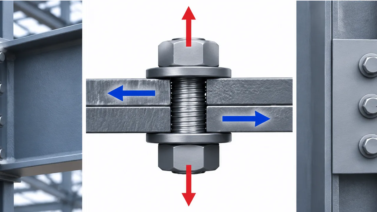
Bolted connections are fundamental to modern structural steel construction because they allow beams, columns, braces, plates, and other members to transfer forces safely while remaining practical to fabricate and erect. Selecting a bolt by diameter alone, however, does not guarantee that a connection can resist its design loads. The bolt material, loading direction, number of shear planes, thread location, plate geometry, hole arrangement, and surrounding connection components all influence the actual resistance.
Bolt capacity design evaluates whether structural bolts can safely resist shear, tension, or a combination of both. It also requires designers to check the surrounding plates, bolt holes, edge distances, connection geometry, and load distribution because the bolt itself is only one part of the complete load path.
This article explains how structural bolt capacity is evaluated under different loading conditions, why combined loading requires interaction checks, and which detailing, fabrication, and installation factors can control the final connection capacity.
What Is Bolt Capacity Design?
Bolt capacity is the resistance that a structural bolt can provide under a specific loading condition. Depending on the connection, a bolt may primarily resist shear, axial tension, or simultaneous shear and tension.
The available capacity depends on several factors, including:
- Bolt diameter
- Bolt grade and material strength
- Threaded or unthreaded section at the critical plane
- Number of shear planes
- Connection geometry
- Hole type and dimensions
- Bolt pretension where applicable
- Plate thickness and material strength
- Applicable structural design standard
A proper design therefore compares the force acting on each bolt with the resistance available from the bolt and the surrounding connection components.
Bolt Capacity vs Connection Capacity
Bolt strength should not be confused with complete connection strength. A high-strength bolt may have substantial shear or tensile resistance, while the connected plate may fail first through bearing, tear-out, net-section fracture, block shear, or local yielding.
The capacity of the entire connection is controlled by its weakest governing failure mode. This is why bolt calculations must be coordinated with plate design, member strength, welds, stiffeners, and the overall load path.
Main Types of Loads Acting on Structural Bolts
Shear Loading
Shear occurs when the applied force acts primarily perpendicular to the bolt axis. The connected plates attempt to slide relative to one another, causing the bolt to resist transverse force across one or more shear planes.
Typical examples include beam splice connections, fin plates, lap joints, bracing connections, and other steel joints subjected to shear loads.
A bolt may be subjected to single shear when there is one critical shear plane, or double shear when two planes pass through the bolt. The number of active shear planes has a direct effect on the available resistance.
Tension Loading
Bolt tension occurs when force acts approximately parallel to the bolt axis and attempts to pull the connected components apart. This condition is common in end-plate connections, flange connections, moment joints, base plates, and other structural details where separation forces develop.
The bolt must resist axial tensile force through its effective tensile area. Depending on the geometry of the connection, additional bolt tension may also develop because of deformation of the connected plate.
Combined Shear and Tension
Many real structural connections do not experience pure shear or pure tension. A bolt may simultaneously resist transverse shear and axial tension due to eccentricity, bending, frame action, or connection geometry.
In this situation, the bolt cannot normally be checked by treating its full shear resistance and full tensile resistance as independently available. The interaction between the two actions must be evaluated.
Bolt Shear Capacity
How Bolts Resist Shear
In a bearing-type connection, shear force is transferred through the bolt shank as the connected plates bear against the bolt. The bolt resists transverse deformation while the surrounding plate resists bearing pressure around the hole.
The design must therefore consider both the shear resistance of the bolt and the bearing resistance of the connected material.
Single Shear vs Double Shear
In a single-shear connection, one shear plane crosses the bolt. A typical lap joint is a simple example. In a double-shear configuration, the bolt passes through three connected layers and develops two shear planes.
Because more than one plane participates in resisting the load, double-shear configurations can provide greater total bolt resistance when the surrounding components are also capable of carrying the load.
Threads in the Shear Plane
The location of the threaded portion of a bolt can affect shear capacity. When threads are included within the critical shear plane, the effective resisting area may be smaller than when the shear plane passes through the full bolt shank.
This makes bolt length, grip length, and connection detailing important parts of structural design rather than simple fabrication choices.
Factors Affecting Bolt Shear Capacity
The principal factors include:
- Bolt diameter
- Bolt material strength
- Number of shear planes
- Thread location
- Connection configuration
- Hole geometry
- Applicable resistance factors or safety factors
A reliable bolt capacity design checks these conditions together with the resistance of the connected plate.
Bolt Tension Capacity
How Structural Bolts Resist Tension
When a bolt is loaded in tension, axial force develops along the bolt and attempts to elongate it. The threaded section generally provides a smaller effective tensile area than the gross shank area and is therefore an important part of the resistance calculation.
Structural design must ensure that the applied tensile demand remains below the permitted bolt resistance after the required design factors are applied.
Tensile Failure of the Bolt
Possible tensile failure mechanisms include:
- Yielding of the bolt
- Tensile fracture
- Thread stripping
- Excessive bolt elongation
- Localized damage at threaded regions
Proper bolt grade selection and installation are necessary to achieve the resistance assumed in the structural calculations.
Prying Action
Prying action can increase bolt tension beyond the direct force predicted from simple equilibrium. It occurs when a flexible end plate, flange, or connection plate bends and develops additional reaction forces near the bolt.
This behavior is especially important in end-plate and flange connections. If prying action is ignored, the actual bolt demand may be significantly higher than the calculated direct tensile force.
Factors Affecting Bolt Tension Capacity
- Bolt diameter
- Bolt grade
- Effective tensile stress area
- Thread condition
- Bolt pretension
- Plate stiffness
- Connection geometry
- Prying effects
Combined Shear and Tension in Bolts
Why Combined Loading Requires Interaction Checks
A bolt subjected to both shear and tension is using part of its available strength to resist each action. As shear demand increases, less capacity is effectively available for tension, and the same principle applies in the opposite direction.
Structural design standards therefore use interaction relationships or utilization checks to determine whether the combined force state remains acceptable.
Interaction Between Shear and Tension
A bolt may experience several combinations of loading:
- Low shear with high tension
- High shear with low tension
- Moderate shear and moderate tension
- High simultaneous shear and tension approaching the interaction limit
The allowable relationship depends on the applicable design standard and bolt type. Designers should not assume that passing the individual shear and tension checks automatically means the combined condition is safe.
Typical Connections with Combined Bolt Loading
Combined loading commonly occurs in:
- Moment end-plate connections
- Bracing connections
- Eccentric brackets
- Column splices
- Base plate anchor assemblies
- Equipment support structures
Bearing Resistance Around Bolt Holes
A bolt with sufficient shear resistance can still be part of an inadequate connection if the surrounding plate cannot resist bearing pressure. As the bolt pushes against the side of the hole, concentrated stresses develop within the plate.
Plate Bearing Failure
Excessive bearing stress can cause local crushing, permanent deformation, or elongation of the bolt hole. Plate bearing resistance depends on material strength, plate thickness, bolt diameter, edge distance, spacing, and the geometry of the hole.
Edge Tear-Out
When a bolt is positioned too close to the plate edge, the material between the hole and the free edge may tear out. Increasing bolt strength alone does not prevent this failure.
Adequate edge distance is therefore necessary to provide a sufficient length of material for transferring the bolt force into the plate.
Bolt Spacing
Bolts placed too closely together may create overlapping stress zones and reduce the effectiveness of the connected plate. Proper spacing is also necessary for fabrication, installation, tightening, and inspection.
Bolt Group Capacity
Load Distribution Between Multiple Bolts
Many connections use a group of bolts rather than a single fastener. Under simple concentric loading and sufficiently rigid connection behavior, the total force may be idealized as being distributed between the bolts.
However, real force distribution can change when the connection deforms, the load is eccentric, or some bolts are positioned farther from the center of rotation.
Eccentrically Loaded Bolt Groups
When the applied force does not pass through the centroid of the bolt group, it creates both direct shear and a moment. This moment introduces additional forces that vary with bolt position.
Bolts farther from the group centroid may experience larger forces than bolts near the center. Simply dividing the total load by the number of bolts can therefore underestimate the demand.
Bolt Group Geometry
Important geometric parameters include:
- Number of bolts
- Number of rows and columns
- Bolt spacing
- Gauge distance
- Edge distances
- Bolt group centroid
- Direction and eccentricity of the applied force
High-Strength Bolts and Pretension
Bearing-Type Bolted Connections
In bearing-type connections, the force is ultimately transferred through contact between the bolt and the connected plate. Small relative movement may occur before full bearing is developed, depending on hole geometry and installation conditions.
Slip-Critical Connections
Slip-critical connections are designed so that load is initially transferred through friction between the connected faying surfaces. Bolt pretension clamps the plates together, allowing friction to resist movement.
The resistance of these connections depends not only on bolt strength but also on the surface condition, pretension level, hole type, and number of friction interfaces.
When Pretension Becomes Important
Pretension is especially important where connection slip, vibration, fatigue, or repeated load reversal must be controlled. Typical examples include:
- Bridge connections
- Crane-supporting structures
- Vibration-sensitive equipment frames
- Fatigue-sensitive connections
- Connections with repeated or reversing loads
Common Bolt Failure Modes
Bolt Shear Failure
Bolt shear failure occurs when transverse force exceeds the available shear resistance and the bolt fractures across one or more shear planes.
Bolt Tensile Fracture
Tensile fracture occurs when axial tension exceeds the available tensile strength of the bolt, often at the effective threaded section.
Combined Shear-Tension Failure
Even when separate shear and tension values appear acceptable, the combined utilization may exceed the permitted interaction limit.
Bearing Failure
Excessive pressure between the bolt and the plate can deform the hole or crush the surrounding material.
Edge Tear-Out
Insufficient edge distance may allow the plate material between a bolt hole and the free edge to tear away.
Thread Failure
Incorrect bolt-nut combinations, damaged threads, inadequate engagement, or excessive load can result in thread stripping or localized thread failure.
Connection Plate Failure
The plate may fail before the bolt through net-section fracture, block shear, local yielding, bearing, or tear-out. This demonstrates why bolt resistance alone cannot define the capacity of a complete connection.
Important Bolt Capacity Design Considerations
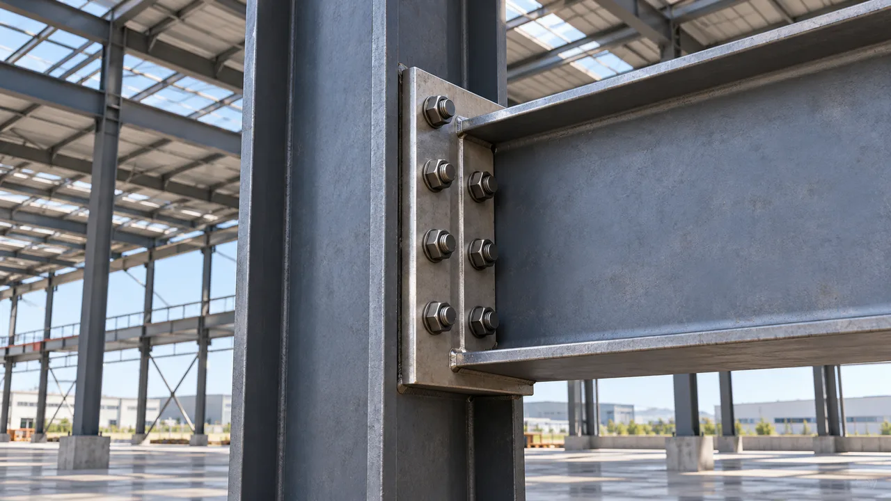
Bolt Grade
Higher-strength bolt grades generally provide greater nominal resistance, but a stronger bolt does not automatically produce a stronger connection. Plate strength, thickness, hole geometry, and supporting-member resistance may still control the design.
Bolt Diameter
Increasing bolt diameter generally increases bolt shear and tensile resistance. However, larger bolts require larger holes, which reduce the net area of the connected plate and can affect spacing and edge-distance requirements.
Plate Thickness
Thin plates may experience bearing deformation, tear-out, or local yielding before the full resistance of a high-strength bolt can be developed.
Hole Type
Bolted steel connections may use standard, oversized, or slotted holes depending on structural and erection requirements. Hole geometry can affect bearing behavior, slip resistance, available net area, and installation tolerance.
Edge Distance and Spacing
Proper bolt spacing and edge distance provide sufficient material for force transfer while also allowing practical fabrication, installation, and inspection.
Connection Geometry
Eccentricity, bolt arrangement, load direction, member stiffness, and connection layout influence how forces are distributed between individual bolts and surrounding plates.
Bolt Capacity Under Static, Cyclic, and Fatigue Loading
Static Loads
Static connections are primarily evaluated on the basis of strength under loads that are constant or change slowly. The governing checks typically include bolt shear, bolt tension, bearing, plate failure, and connection stability.
Repeated and Cyclic Loads
Crane structures, machinery supports, seismic systems, and other structures can experience repeated or reversing forces. These conditions may influence bolt pretension, slip behavior, and stress distribution.
Fatigue Considerations
A connection may experience fatigue even when its maximum force remains below its static strength. Repeated stress ranges can initiate cracks or gradually damage connection components over many loading cycles.
Pretension, slip resistance, connection stiffness, hole geometry, and stress concentration therefore become important considerations in fatigue-sensitive applications.
Design Workflow for Bolt Capacity
Step 1 — Determine Applied Forces
Identify all relevant shear, tension, moment, eccentricity, and combined loading acting on the connection.
Step 2 — Select Initial Bolt Size and Grade
Choose an initial bolt diameter, grade, and arrangement based on the expected structural demand and connection type.
Step 3 — Check Bolt Shear Capacity
Evaluate bolt shear resistance considering material strength, number of shear planes, thread location, and connection configuration.
Step 4 — Check Bolt Tension Capacity
Evaluate direct bolt tension and include additional effects such as prying where applicable.
Step 5 — Check Combined Shear and Tension
Apply the required interaction check when both force components act on the same bolt.
Step 6 — Check Plate and Hole Resistance
Evaluate bearing, edge tear-out, net-section fracture, block shear, and other plate failure modes.
Step 7 — Check Bolt Group Behavior
Confirm that the assumed force distribution is appropriate for concentric or eccentric loading.
Step 8 — Verify Detailing and Constructability
Check bolt spacing, edge distances, installation clearance, wrench access, erection tolerances, tightening requirements, and inspection access.
Fabrication and Installation Considerations
Hole Preparation
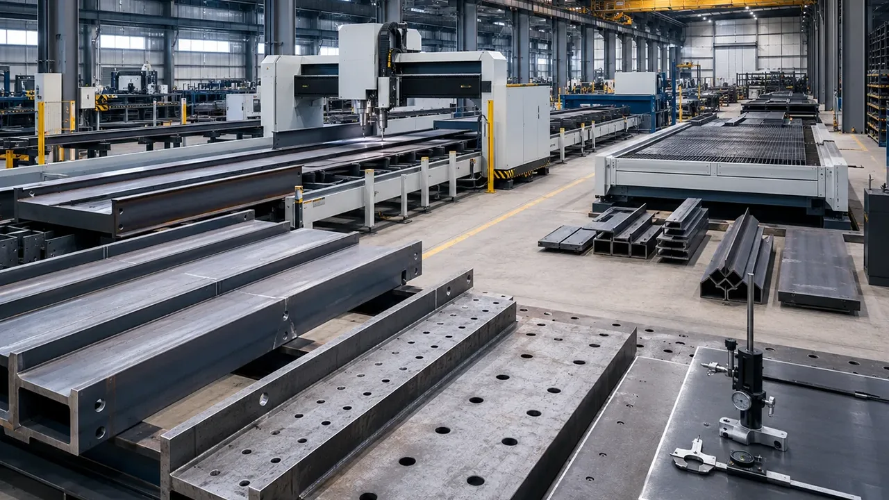
Bolt holes may be produced by drilling, punching, CNC machining, or other approved fabrication methods. Accurate hole dimensions and positioning are necessary to achieve proper fit-up and the connection geometry assumed in design.
Bolt Installation
Installation teams should verify bolt grade, diameter, nuts, washers, orientation, hole alignment, and tightening requirements before completing the connection.
Pretensioning
Where bolt pretension is specified, approved installation procedures should be used to achieve the required clamping force. Installation method, calibration, bolt condition, and inspection should correspond to the governing project requirements.
Inspection
Inspection may include:
- Verification of bolt identification and grade
- Confirmation of bolt diameter and quantity
- Checking nuts and washers
- Inspection of damaged or contaminated threads
- Verification of tightening or pretensioning
- Checking bolt-hole alignment
- Confirmation of required installation access
XTD Steel Structure coordinates connection detailing with controlled fabrication and dimensional inspection to help ensure that bolted components can be assembled according to their intended structural configuration.
Common Bolt Design Mistakes
Several recurring errors can reduce the reliability of bolted connections:
- Checking bolt shear while ignoring plate bearing
- Ignoring bolt tension caused by prying action
- Checking shear and tension independently when combined interaction governs
- Assuming equal force distribution in an eccentric bolt group
- Ignoring the location of threads within the shear plane
- Providing insufficient edge distance
- Using excessively close bolt spacing
- Specifying an incorrect bolt grade
- Using oversized or slotted holes without evaluating their structural effect
- Ignoring fatigue or cyclic loading
- Providing inadequate installation access
- Assuming higher bolt strength automatically increases complete connection capacity
Structural Applications of Bolt Capacity Design
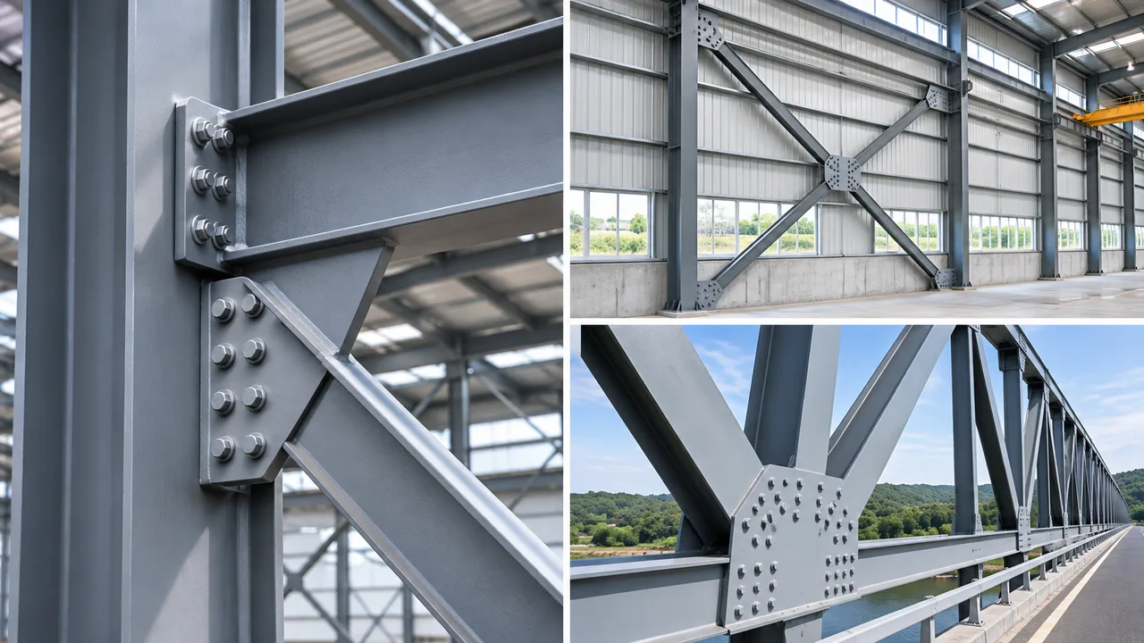
Steel Buildings
Bolted connections are widely used throughout a Steel structure, including beam-to-column joints, column splices, bracing systems, roof framing, and secondary structural connections.
Different connections may place the bolts primarily in shear, tension, or combined loading depending on how structural forces move through the frame.
Industrial Buildings and Factories
Industrial facilities use structural bolts in crane-supporting frames, equipment platforms, production buildings, mezzanines, maintenance structures, and machinery supports. These applications may include vibration, eccentric loading, or repeated forces that require more than a basic static bolt check.
Steel Warehouses
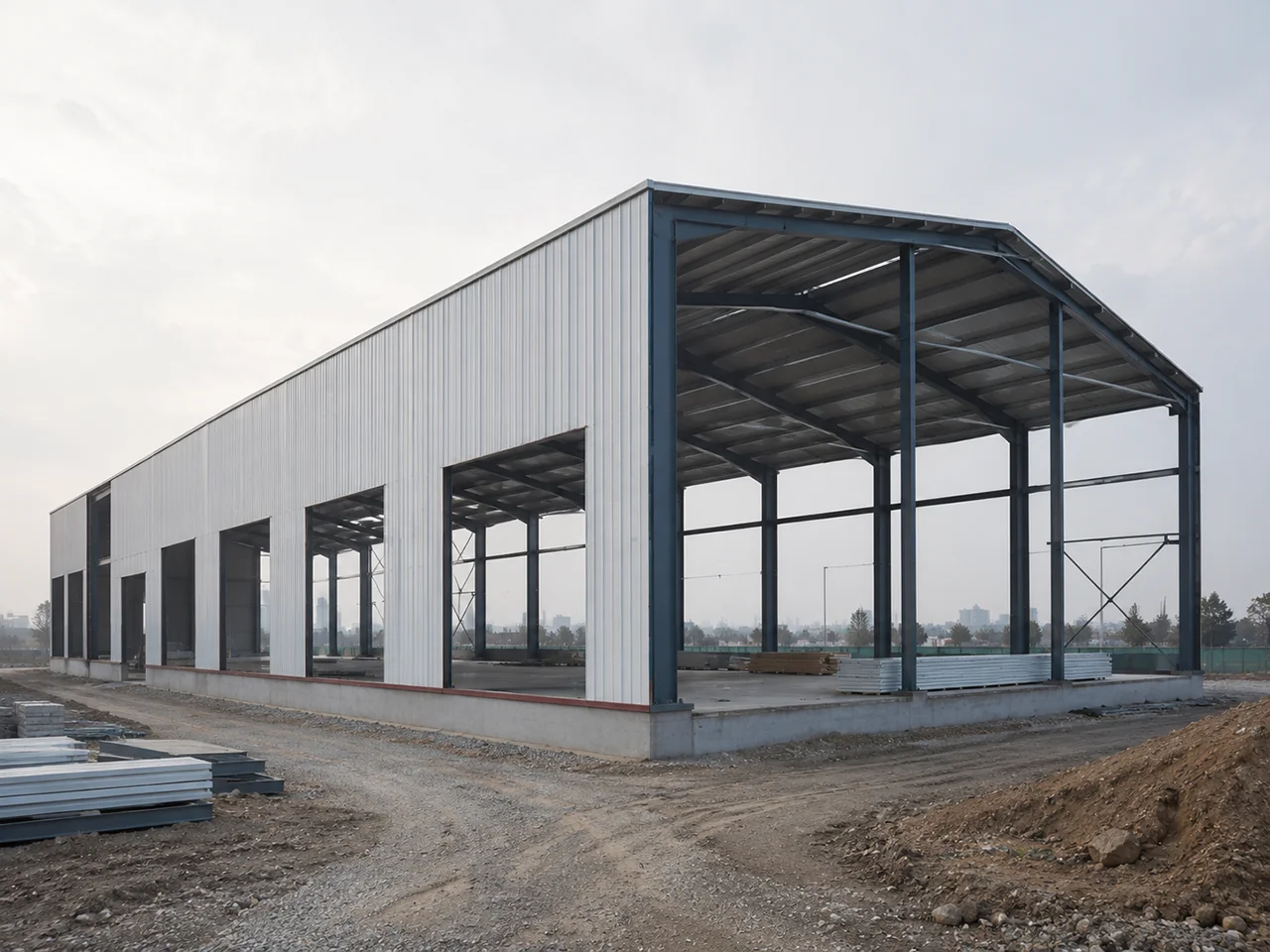
Portal-frame warehouses use bolted connections in main frames, roof bracing, wall bracing, purlin systems, splices, and secondary framing. Efficient detailing can reduce site welding and accelerate structural erection.
Bridges and Infrastructure
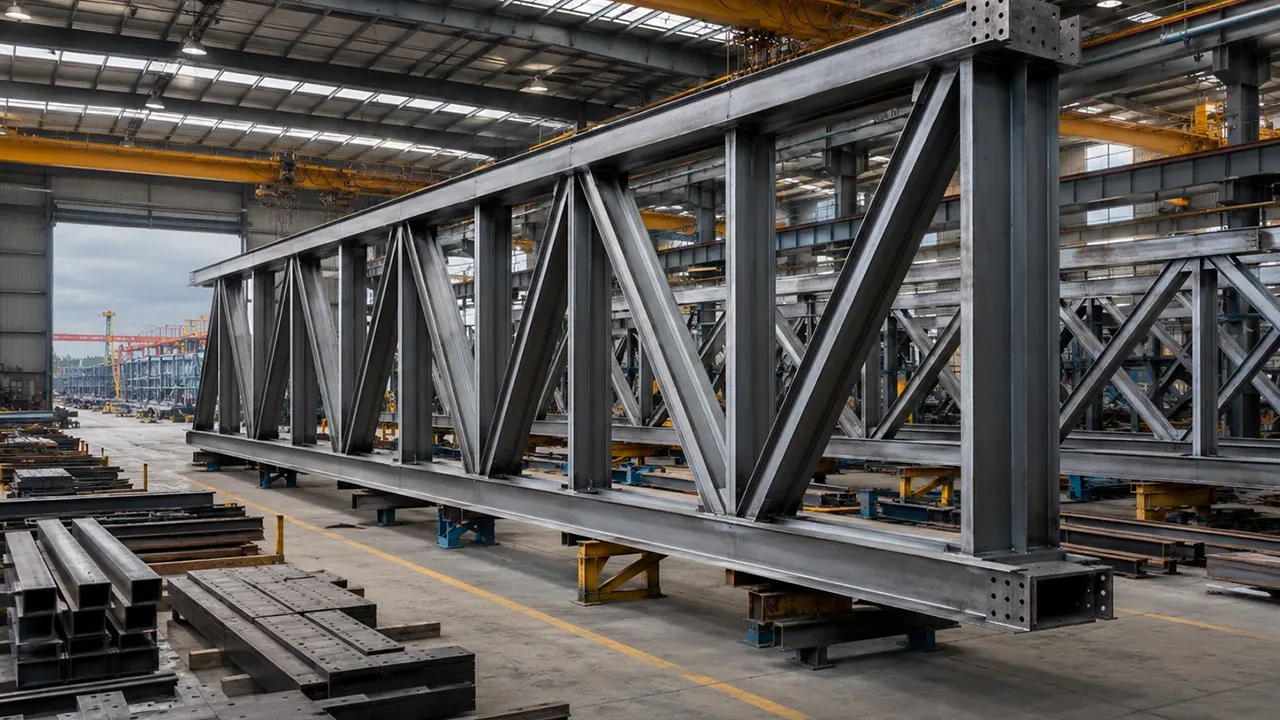
Bridge structures use high-strength bolts in splices, truss joints, cross-bracing, diaphragms, and other heavily loaded connections. Fatigue and slip resistance may become especially important because of repeated traffic loading.
Towers and Equipment Structures
Communication towers, transmission towers, pipe racks, industrial platforms, and machinery-support frames frequently use bolted joints because they can be fabricated in sections and efficiently assembled on site.
Frequently Asked Questions
What Determines Bolt Capacity?
Bolt capacity depends on bolt diameter, material grade, loading direction, number of shear planes, thread location, connection geometry, hole type, and the governing structural design standard. The connected plates and surrounding members must also be checked.
How Is Bolt Shear Capacity Different from Bolt Tension Capacity?
Shear capacity resists forces acting primarily perpendicular to the bolt axis, while tension capacity resists forces acting along the bolt axis and attempting to separate the connected components.
Can a Bolt Carry Shear and Tension at the Same Time?
Yes. Structural bolts can carry simultaneous shear and tension, but the combined force state must satisfy the interaction requirements of the applicable design standard.
Does a Larger Bolt Always Provide a Stronger Connection?
No. A larger bolt can provide greater nominal bolt resistance, but the plate may still be controlled by bearing, net-section fracture, block shear, edge tear-out, or other connection failure modes.
What Is the Difference Between Bearing-Type and Slip-Critical Bolt Connections?
In a bearing-type connection, load is transferred primarily through contact between the bolt and the plate after relative movement develops. In a slip-critical connection, pretensioned bolts create clamping force so that friction between the connected surfaces resists slip.
Conclusion
Bolt capacity design requires more than checking the nominal strength of a structural bolt. A reliable connection must consider shear resistance, tensile resistance, combined loading, bearing, bolt-group behavior, plate failure modes, pretension, connection geometry, and installation requirements.
The governing resistance may come from the bolt, the plate, the bolt hole, or another part of the connection. Treating the bolted joint as a complete load-transfer system helps engineers avoid local failures and ensures that forces move safely through the structure.
Coordinated engineering, accurate fabrication, controlled installation, and proper inspection are therefore essential for achieving dependable bolted connections throughout the service life of a steel structure.