Steel structures must resist more than vertical weight. Forces move through beams, columns, braces, plates, bolts, welds, base plates, and foundations. Some forces pull or push along the length of a member, while others create bending or sliding action across a section. In steel structure design, beams and connections may carry vertical shear, bending moments, and axial loads at the same time, so each force must be checked through a clear and continuous load path.
Shear loads are forces that act parallel to a surface or cross-section and tend to make one part of a member slide past another. In steel beams, shear usually appears as an internal force caused by vertical reactions. In steel connections, shear is transferred through bolts, welds, end plates, shear tabs, gusset plates, and supporting members. Understanding how shear works is essential for safe beam design, reliable connection detailing, and long-term steel structure performance.
What Are Shear Loads in Steel Structures?
Shear loads create internal sliding action inside a member or connection. When a beam supports roof panels, floor systems, crane loads, or equipment platforms, the applied load must travel through the beam and into the supports. This load transfer creates internal shear force, especially near the support locations where reactions are concentrated.
In simple terms, shear tries to cut or slide one part of the steel section relative to another. A beam web may resist vertical shear. A bolt may resist shear when two connected plates try to move in opposite directions. A weld may transfer shear along its effective throat. A connection plate may resist shear as force moves from a beam into a column or main frame.
Shear Force in Beams
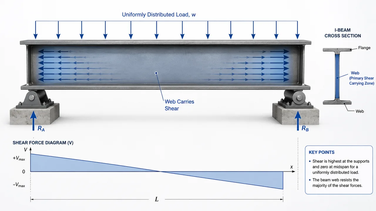
In steel beams, shear force is commonly highest near the supports. The beam receives loads from roofing, floors, machines, purlins, wall framing, or crane systems, then transfers those loads to columns or other supporting members. While the flanges mainly resist bending, the web usually carries most of the shear force.
Shear Force in Connections
Connections must transfer the reaction force from one steel member to another. A beam-to-column connection, for example, may need to transfer vertical shear from the beam end into the column flange or web. If bolts, welds, plates, or supporting areas are not designed properly, the connection can become the weak point even when the beam itself has enough capacity.
Shear vs Axial Load vs Moment
Shear acts across a section and creates sliding action. Axial load acts along the length of a member in tension or compression. Moment creates bending or rotational effect. In real steel structures, these forces often appear together. A beam end connection may carry shear and moment. A bracing connection may transfer axial force through bolts that experience shear. A column base may resist compression, shear, and uplift depending on the load case.
Where Shear Loads Commonly Appear
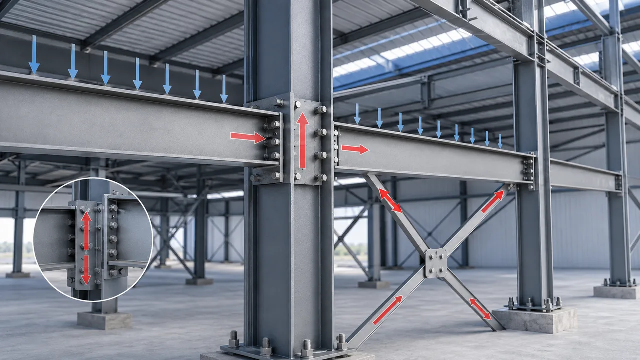
Shear force can appear in almost every part of a steel structure. It is especially important in beams, beam-to-column connections, bolted joints, welded details, gusset plates, end plates, and areas near concentrated loads.
Steel Beams
Steel beams resist shear from roof loads, floor loads, crane loads, mezzanine platforms, equipment reactions, and wall framing. In industrial buildings, beams may support concentrated loads from machines, service platforms, pipe racks, or crane runway systems. These conditions can increase shear demand and may require deeper sections, thicker webs, or additional stiffeners.
Beam-to-Column Connections
Beam-to-column connections often transfer shear from the beam end into the supporting column. Common connection types include shear tabs, clip angles, end plates, and welded seat details. The connection must be strong enough to carry the beam reaction while maintaining proper alignment and installation tolerance.
Bolted Connections
Bolts carry shear when connected plates try to slide past each other. Bolt shear capacity depends on bolt diameter, bolt grade, number of bolts, number of shear planes, hole quality, and connection layout. Bearing around the bolt holes must also be checked because the connected plate can deform or tear even if the bolt itself is strong enough.
Welded Connections
Welds transfer shear through weld length, weld size, effective throat, weld direction, and base metal quality. A weld that is too short or poorly placed may not transfer the required force safely. Weld access, inspection, and fabrication quality are also important because connection performance depends heavily on workmanship.
Gusset Plates and End Plates
Gusset plates and end plates are often used to transfer forces between braces, beams, columns, and truss members. These plates must have enough thickness, edge distance, hole spacing, and geometry to resist shear without local yielding, tearing, or excessive deformation.
How Shear Loads Affect Steel Beams
In a typical steel beam, bending moment and shear force work together. The flanges carry most of the bending stress, while the web carries much of the shear. This is why web thickness, web depth, and web stability are important parts of beam design.
Shear is often highest near supports because the beam reaction is transferred into the column, wall, girder, or supporting frame at those locations. When heavy loads are placed close to a support, shear demand can become especially high. Concentrated loads from cranes, equipment, or mezzanine columns may also create local stress in the beam web.
If the web is too thin, it may experience web yielding, web buckling, or local deformation. In some situations, stiffeners are added near supports or concentrated load points to strengthen the web and distribute force more effectively. Plate girders, crane beams, and heavy industrial framing often require more detailed shear checks than light secondary beams.
Shear Loads in Steel Structure Connections
A beam with enough member strength can still fail if its connection cannot transfer the force safely. This is why shear loads must be checked not only in the beam but also in the complete connection system.
At a beam end, the vertical reaction may pass through bolts, welds, shear plates, clip angles, end plates, or bearing seats. Each part of the connection must be aligned with the intended load path. If the plate is too thin, the bolt group is too small, or the weld is too short, the connection may deform or fail before the main member reaches its design capacity.
Connection geometry also matters. Hole spacing, edge distance, plate thickness, bolt layout, weld direction, and access for installation all influence how the connection performs. Poor alignment can introduce secondary bending, eccentric shear, or uneven bolt loading. For fabricated steel structures, connection detailing is where engineering design, workshop production, and site installation must work together.
Shear Loads in Bolts and Welds
Bolts and welds are often the most direct components transferring shear between connected steel parts. Their design must consider not only nominal force capacity but also the way force enters and leaves the connection.
Bolt Shear
Bolt shear occurs when connected plates try to slide in opposite directions across the bolt shank. The bolt must resist this sliding action through one or more shear planes. The capacity depends on bolt diameter, grade, number of bolts, thread position, and whether the connection is in single shear or double shear.
Plate bearing is also important. Even if the bolt has enough shear capacity, the connected plate can deform around the hole. Edge distance and bolt spacing help prevent tearing, splitting, or block shear failure.
Weld Shear
Weld shear depends on weld size, effective throat, weld length, weld layout, and the quality of both weld metal and base metal. Fillet welds are commonly used in steel structure connections, but they must be sized according to the actual force direction and connection geometry.
Combined Shear and Tension
Many real connections do not carry pure shear only. Bolts and welds may also experience tension, prying action, eccentric force, or moment effects. A connection that looks simple in the drawing may require combined force checks when load direction, plate geometry, or member eccentricity creates additional stress.
Web Shear, Web Buckling, and Stiffeners
Beam webs are designed to transfer shear through the vertical plate area between the flanges. When the web is thick enough and properly supported, it can carry shear efficiently. When the web is thin or the load is concentrated, additional checks may be needed.
Web buckling can occur when a slender web plate loses stability under high shear. Web local yielding can occur near bearing areas where concentrated force is introduced. Web crippling may appear near supports or load points if the web cannot distribute the load properly.
Stiffeners are often used to improve performance in these critical areas. Bearing stiffeners can help transfer concentrated loads. Intermediate stiffeners can improve web stability in deeper girders. For heavy-duty steel structures, these details can be essential for safe and economical design.
Shear Loads in Bracing and Truss Connections
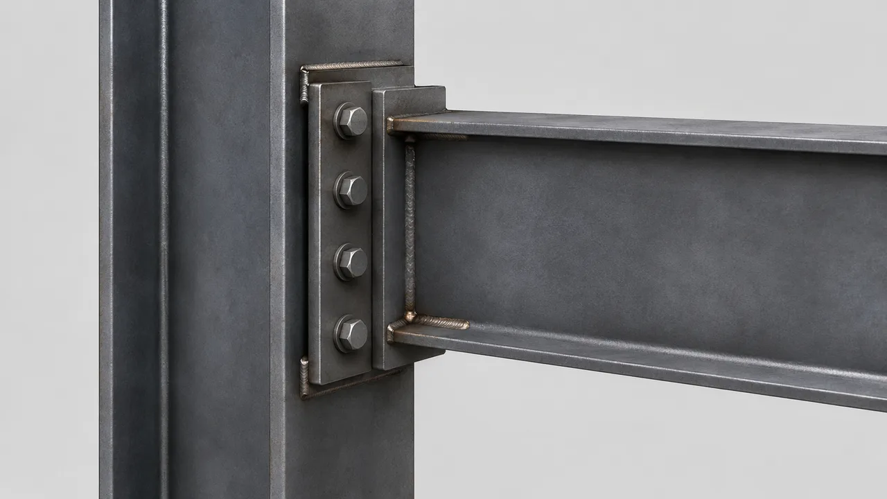
Bracing and truss members often carry axial forces along their length, but their connections usually transfer these forces through shear in bolts, welds, and plates. A diagonal brace, for example, may deliver axial force into a gusset plate, while the bolts and welds in that plate must transfer the force into the beam-column joint.
Truss panel points also need accurate shear transfer. If the connection is misaligned, the force may not pass cleanly through the intended node. This can introduce secondary shear, bending, or local plate deformation. For long-span roofs and industrial steel buildings, small connection errors can become significant when the member forces are high.
Comparison of Shear Behavior in Steel Components
| Component | How Shear Appears | Key Design Concern | Typical Detail |
|---|---|---|---|
| Steel beam web | Vertical shear from beam reaction | Web yielding or web buckling | Web thickness, bearing stiffeners |
| Bolted connection | Plates sliding across bolt shank | Bolt shear and plate bearing | Bolt diameter, spacing, edge distance |
| Welded connection | Force transferred through weld throat | Weld size, length, and direction | Fillet weld or groove weld |
| End plate | Beam reaction transfer | Plate bending and bolt force | End plate thickness and bolt layout |
| Gusset plate | Brace or truss force transfer | Local yielding and block shear | Plate geometry and weld or bolt detail |
Common Mistakes When Designing for Shear Loads
One common mistake is checking beam bending while ignoring beam shear. A beam may have enough bending capacity but still require web checks near supports or concentrated load points. This is especially important in crane beams, transfer beams, mezzanine beams, and industrial platforms.
Another mistake is designing the steel member but underdesigning the connection. If the beam reaction is high, the connection must have enough bolts, weld length, plate thickness, and supporting area. Too few bolts, insufficient edge distance, or weak plate geometry can create unsafe shear transfer.
Designers may also assume that shear acts alone. In reality, shear may combine with bending moment, axial force, tension, uplift, or eccentricity. Ignoring combined effects can lead to unsafe connection details or unexpected deformation during service.
Why Load Path Matters for Shear Design
Shear force must move continuously from the applied load into the beam, web, connection, column, bracing system, base plate, and foundation. A strong beam with a weak connection is unsafe. A strong connection attached to a weak supporting web can also fail. The complete load path must be checked, not just one isolated member.
Fabrication tolerance and installation quality affect how this load path works in reality. Misaligned holes, poorly fitted plates, incomplete welds, or incorrect bolt tightening can change the way shear is distributed. This is why shear design should be coordinated with shop drawings, fabrication methods, quality inspection, and site erection planning.
How XTD Steel Structure Supports Shear Load Design
For steel warehouses, factories, industrial platforms, and long-span buildings, shear behavior must be considered from early structural design through fabrication and installation. XTD Steel Structure supports steel building projects by coordinating member fabrication, connection detailing, bolt and weld layout, plate processing, quality inspection, and project installation requirements.
This integrated approach helps ensure that beams, columns, braces, connection plates, bolts, and welds are not treated as separate parts. Instead, they are coordinated as one complete steel structure system so shear force can move through the building safely and efficiently.
Practical Takeaway for Steel Structure Projects
Shear loads are essential in beam and connection design. They affect beam webs, bolts, welds, plates, gusset connections, end plates, and supporting members. Good shear design requires more than selecting a steel section. It requires a clear load path, correct connection details, adequate fabrication tolerance, and proper installation quality.
For project owners, contractors, and engineers, understanding shear behavior helps improve structural safety, connection reliability, and long-term building performance. Whether the project is a warehouse, factory, platform, truss roof, or heavy industrial steel structure, shear force must be designed and transferred carefully from one part of the structure to another.
FAQ About Shear Loads
What Are Shear Loads in Steel Structures?
Shear loads are forces that act parallel to a surface or cross-section and tend to make one part of a steel member or connection slide past another.
Where Are Shear Loads Highest in Beams?
Shear is often highest near beam supports, where vertical reactions are transferred into columns, girders, walls, or other supporting members.
Do Bolts and Welds Carry Shear Loads?
Yes. Bolts and welds often transfer shear between connected steel plates, beams, columns, braces, truss members, and connection plates.
How Are Shear Loads Different from Axial Loads?
Shear acts across a section and creates sliding action, while axial load acts along the length of a member in tension or compression.