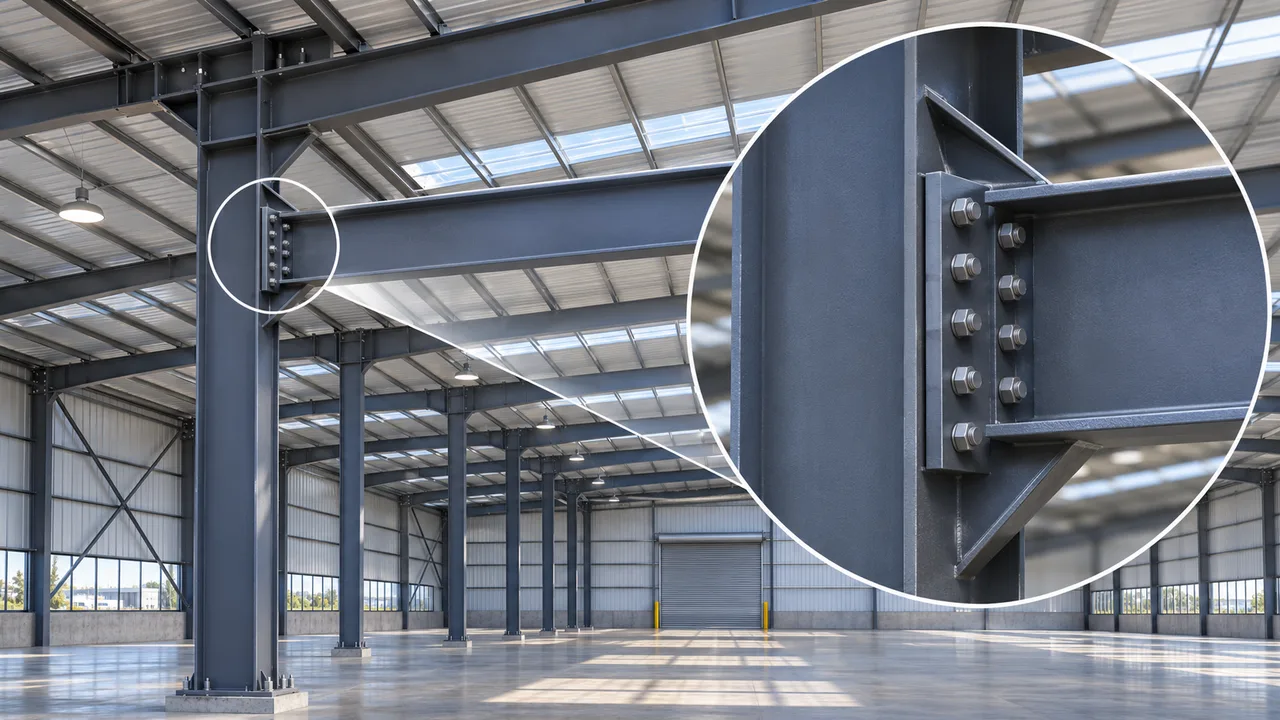
Bolted moment connections rely on more than the nominal strength of individual fasteners. When a beam transfers bending moment into a column, the connection develops a combination of tension and compression forces that must travel through bolts, plates, flanges, welds, and supporting members. Understanding bolt tension capacity is therefore essential for designing moment connections that can transfer these forces safely without shifting failure into a weaker surrounding component.
In practical steel connection design, a bolt may have adequate tensile resistance while the end plate bends excessively, the column flange deforms, or prying action increases the actual force acting on the bolt. Reliable design requires engineers to evaluate the complete load path and understand how bolt tension interacts with connection geometry, plate stiffness, flange behavior, fabrication tolerances, and installation quality.
Understanding Bolt Tension Capacity
What Is Bolt Tension Capacity?
Bolt tension capacity is the resistance of a structural bolt to axial tensile force. When tension acts along the bolt axis, the bolt must resist elongation and ultimately prevent tensile fracture. Its available resistance depends on factors such as bolt diameter, strength grade, threaded tensile area, material properties, and the applicable structural design requirements.
The tensile strength of an individual bolt does not automatically represent the capacity of the complete connection. The connected plate, end plate, column flange, beam flange, welds, and stiffeners must also be capable of transferring the same force safely.
Why Bolt Tension Is Important in Moment Connections
A bending moment is transferred through a force couple consisting of tension on one side of the connection and compression on the opposite side. In a beam-to-column moment connection, the beam flange located in the tension zone transfers force into the end plate or flange plate, which then develops tensile forces in the bolt rows.
The magnitude of bolt tension depends on the applied moment, the distance between the tension and compression resultants, the number and location of bolt rows, and the stiffness of the surrounding components. Bolt tension therefore cannot be evaluated independently from the overall connection geometry.
Bolt Tension Capacity Is Only One Part of the Connection
A connection may contain high-strength bolts with substantial tensile resistance, but that does not guarantee equivalent connection capacity. A thin end plate may bend before the bolts reach their tensile resistance. A flexible column flange may deform locally. Welds connecting the end plate to the beam may govern, or the beam flange itself may yield.
The most reliable design approach evaluates the complete connection rather than maximizing the resistance of one individual component.
How Moment Connections Generate Bolt Tension
Moment Transfer Through Beam Flanges
In a typical beam-to-column moment connection, the beam flanges carry much of the bending effect. One flange develops tension while the opposite flange develops compression. The tensile flange force must pass through the connecting plate and into the column or supporting member.
If an end plate is welded to the beam and bolted to the column, the tensile beam flange force pulls the end plate away from the column face. This action creates tensile demand in the bolts located near the tension flange.
Tension Distribution Between Bolt Rows
Bolt tension is rarely distributed equally among all bolt rows. Bolt rows located farther from the compression zone generally have larger lever arms and may attract higher tensile forces. However, actual force distribution also depends on end-plate stiffness, column flange flexibility, bolt spacing, and interaction between adjacent rows.
For this reason, simply dividing the total tensile force by the number of bolts can produce an unrealistic representation of the connection behavior.
Effect of Connection Geometry
Bolt spacing, edge distance, end-plate dimensions, beam depth, bolt location, and column flange geometry all influence tensile force distribution. Small changes in bolt position can alter the lever arm and therefore the force required to resist a given moment.
Connection geometry also affects plate bending and prying action, which can increase the force carried by individual bolts beyond the value predicted from global equilibrium alone.
Bolt Tension Capacity in End-Plate Moment Connections
Extended End-Plate Connections
Extended end-plate connections position one or more bolt rows beyond the beam flange. This arrangement increases the available lever arm and can provide substantial moment resistance. The external bolt rows may experience high tensile demand because they participate directly in transferring flange tension into the column.
The performance of the connection depends on the relationship between bolt resistance, end-plate bending resistance, column flange stiffness, weld capacity, and any stiffeners provided.
Flush End-Plate Connections
Flush end-plate connections keep the plate within or close to the beam depth. Their compact geometry can be useful where space is limited, but the available lever arms and bolt arrangement differ from extended configurations.
Bolt tension distribution in a flush end plate therefore depends strongly on plate thickness, bolt spacing, beam flange forces, and the stiffness of the supporting column.
Role of End-Plate Thickness
End-plate thickness has a major influence on bolt tension behavior. A relatively flexible plate can bend under tensile flange force and create additional local deformation around the bolts. This deformation may generate prying forces that increase bolt tension.
A thicker plate generally provides greater stiffness and more direct force transfer, but increasing plate thickness indefinitely is not necessarily efficient. The design should balance bolt resistance, plate bending, weld strength, fabrication requirements, and material use.
Factors That Determine Bolt Tension Capacity
Bolt Diameter
Larger-diameter bolts generally provide greater tensile area and therefore greater tensile resistance. However, increasing bolt diameter may require larger holes, greater edge distances, larger connection plates, and additional installation clearance.
Bolt Grade and Material Strength
Higher-strength structural bolts can provide greater tensile resistance, but the surrounding components must be capable of developing that resistance. Using stronger bolts without strengthening the end plate, column flange, or welds may simply move the governing failure mode elsewhere.
Threaded Tensile Area
The threaded portion of a bolt has a smaller effective tensile area than the gross shank area. Tensile resistance is therefore associated with the effective stress area through the threaded region rather than simply the nominal bolt diameter.
This distinction becomes particularly important when evaluating high tensile forces in moment connections.
Bolt Pretension
Pretension is introduced into certain structural bolts during installation to clamp the connected surfaces together. Pretension can improve connection behavior in applications where slip or separation must be controlled, but it should not be confused with available external tensile resistance.
When external tension acts on the connection, changes in bolt force depend on the stiffness relationship between the bolt and the connected components.
Number and Arrangement of Bolts
Increasing the number of bolts can increase connection resistance, but the relationship is not always directly proportional. Bolt rows may attract different forces because of their locations and the flexibility of the surrounding plates.
A well-designed bolt arrangement should provide adequate resistance while maintaining suitable spacing, edge distances, installation access, and practical fabrication geometry.
Prying Action and Its Effect on Bolt Tension
What Is Prying Action?
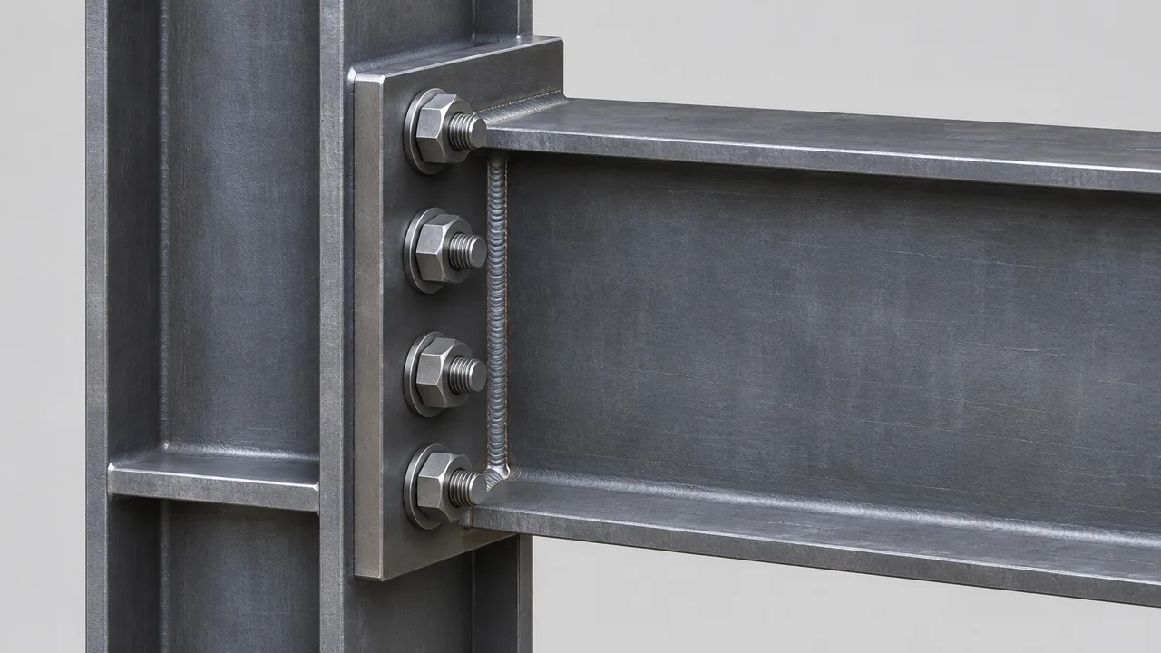
Prying action occurs when deformation of the connected plate creates an additional force that increases bolt tension. Instead of transferring tensile force directly into the bolt, a flexible plate can act like a lever between the bolt line and the plate contact region.
The resulting reaction increases the tensile force in the bolt beyond the value caused by the applied structural load alone.
Why Thin Plates Increase Bolt Demand
Thin or flexible end plates can bend significantly under tensile loading. As the plate bends, contact near an outer edge or another reaction point may create a lever action that increases force in the bolt.
Consequently, a connection with apparently sufficient nominal bolt resistance can become inadequate if prying action is ignored.
How Prying Can Reduce Connection Efficiency
Higher bolt forces caused by prying can reduce the margin between applied demand and available tensile resistance. They can also increase deformation and influence fatigue performance where loading is repetitive.
Efficient connection design therefore seeks to control excessive plate deformation rather than relying only on stronger bolts.
Methods to Control Prying Action
Prying action can be reduced by increasing plate stiffness, adjusting bolt spacing, improving edge geometry, increasing plate thickness, modifying bolt-row locations, or providing suitable stiffeners. The appropriate solution depends on the complete connection configuration rather than one isolated dimension.
Bolt Tension and Flange Local Bending
High tensile forces in moment-connection bolts can create significant local forces in the supporting column flange. As the bolts pull the end plate toward the column, the column flange may bend locally between the web, flange edges, and bolt lines. This interaction makes flange local bending an important limit state when evaluating high-capacity bolted moment connections.
How Column Flange Flexibility Affects Bolt Forces
A flexible column flange may deform outward around the tension bolts. This deformation changes the stiffness of the load path and may contribute to additional prying-type effects or unequal bolt-row force distribution.
A connection with strong bolts and a thick end plate may therefore still be controlled by the local behavior of the supporting column flange.
When Stiffeners May Be Required
Column stiffeners may be required when tensile flange forces or bolt forces exceed the local resistance of the column flange or web region. Stiffeners can improve force distribution, reduce local deformation, and provide a more direct path for transferring beam flange forces into the column.
Their use should be coordinated with weld access, fabrication sequence, member geometry, and overall connection detailing.
Interaction Between Bolt Tension and Shear
Combined Tension and Shear Loading
Bolts in moment connections may experience tension and shear simultaneously. Shear may result from vertical beam reactions, while tension develops from moment transfer or axial loading.
A bolt that has sufficient resistance for pure tension may not have the same available resistance when significant shear is also present.
Why Interaction Checks Matter
Combined loading changes the utilization of the bolt. Structural design therefore requires the interaction between tensile and shear demands to be evaluated where both actions are significant.
Ignoring this interaction can overestimate the available resistance of the bolt and the complete connection.
Load Distribution Within the Bolt Group
Some bolts may carry primarily shear while others experience larger tensile forces depending on the connection geometry. In other arrangements, individual bolts may carry both actions simultaneously.
Accurate connection design therefore requires a realistic understanding of how the bolt group participates in moment, shear, and axial force transfer.
Common Failure Modes Related to Bolt Tension
Bolt Tensile Fracture
Bolt tensile fracture occurs when axial tensile demand exceeds the available resistance of the bolt. High-strength bolts can resist substantial forces, but they still require correct sizing, installation, and compatible connection geometry.
Thread Failure
The threaded region is typically the critical tensile section because its effective area is smaller than the gross shank area. Tensile design should therefore account for the actual stress area of the bolt.
End-Plate Bending
An end plate may yield or deform before the bolt reaches its ultimate tensile resistance. Excessive plate flexibility can also increase bolt demand through prying action.
Column Flange Bending
The column flange may bend locally under concentrated tensile bolt forces. This limit state can control the connection even when bolt and end-plate resistance appear adequate.
Prying-Induced Bolt Failure
If plate deformation creates significant prying forces, the actual tensile force in the bolt may become substantially larger than the force calculated from the basic applied moment.
Weld or Base Metal Failure
Moment connections also rely on welds and connected steel to transfer force. A strong bolt group provides little benefit if a beam flange weld, end-plate weld, column flange, or surrounding base metal fails first.
Bolt Tension Capacity vs Connection Capacity
| Factor | Bolt Tension Capacity | Overall Moment Connection Capacity |
|---|---|---|
| Bolt strength | Directly controls bolt resistance | Only one component of the connection |
| End-plate thickness | Indirect influence | Major influence on connection behavior |
| Column flange | Not part of individual bolt strength | May govern connection resistance |
| Prying action | Increases bolt demand | Can reduce connection efficiency |
| Weld strength | Does not change bolt material strength | May govern the complete connection |
| Stiffeners | Do not change bolt material strength | Can improve force transfer and stiffness |
| Geometry | Affects bolt force distribution | Strongly affects overall resistance |
How Bolt Tension Capacity Is Evaluated in Design
Determine Applied Moment and Axial Forces
The design process begins by identifying the forces acting on the connection. These may include bending moment, shear, axial tension or compression, and combinations of these actions.
Establish the Compression and Tension Zones
The engineer identifies where compression and tension resultants develop within the connection. Their separation creates the lever arm required to resist the applied moment.
Calculate Bolt-Row Forces
Bolt-row forces are determined according to the connection geometry, stiffness assumptions, and selected structural model. Different bolt rows may carry significantly different tensile forces.
Check Individual Bolt Tension Resistance
Each critical bolt or bolt row must provide sufficient tensile resistance for the calculated demand. Bolt diameter, grade, tensile area, and applicable resistance factors must be considered.
Check Combined Tension and Shear
Where bolts are subjected to both actions, their interaction should be evaluated rather than checking tension and shear as completely independent effects.
Check the Surrounding Connection Components
The design should also evaluate end-plate bending, column flange behavior, beam flange forces, weld resistance, stiffeners, base metal, and other applicable limit states.
This complete approach ensures that bolt tension capacity is coordinated with the resistance of the entire connection.
Bolt Tension Capacity in Different Steel Frame Connections
Beam-to-Column Moment Connections
Beam-to-column moment connections frequently use bolted end plates, flange plates, or combinations of shop welding and field bolting. The tension-side bolts must transfer beam flange forces safely into the supporting column.
Beam Splice Connections
Beam splices can develop bolt tension when flange splice plates transfer bending moments between beam segments. Bolt arrangement, plate thickness, and splice geometry determine how these forces are distributed.
Column Splice Connections
Column splices may be subjected to axial force, bending moment, or both. Where tensile forces develop across the splice, bolts and splice plates must transfer the resulting tension between column segments.
Bracket and Cantilever Connections
Brackets and cantilevered supports often produce significant eccentricity. The resulting moment can create high tensile forces in bolts located away from the compression-bearing region.
Industrial Steel Frames
Industrial frames may experience crane loads, machinery forces, dynamic loading, wind, and repeated moment demands. Bolt tension behavior must therefore be considered together with fatigue, stiffness, fabrication, and erection requirements.
Fabrication and Installation Considerations
Accurate Bolt Hole Positioning
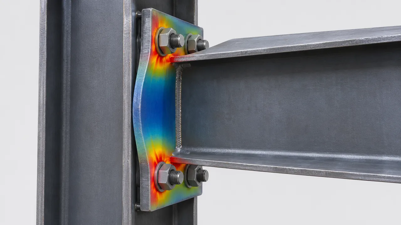
Incorrect hole positioning can create fit-up problems, reduce installation efficiency, and alter the intended load distribution. Accurate drilling and fabrication tolerances are therefore essential for high-capacity moment connections.
Proper Bolt Installation
Bolts must have the specified diameter and grade and should be installed with the correct washers, tightening procedure, and pretension where required. Installation quality directly affects whether the connection performs as intended.
End-Plate Flatness and Fit-Up
Poor plate flatness or uneven contact can influence connection stiffness and the actual path of force transfer. Fabrication should control plate distortion and maintain suitable fit-up between connected components.
Factory Quality Control
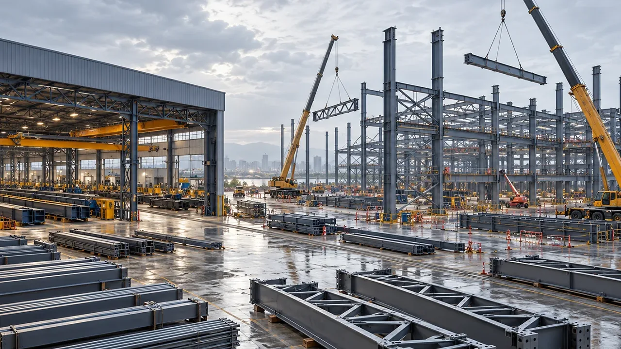
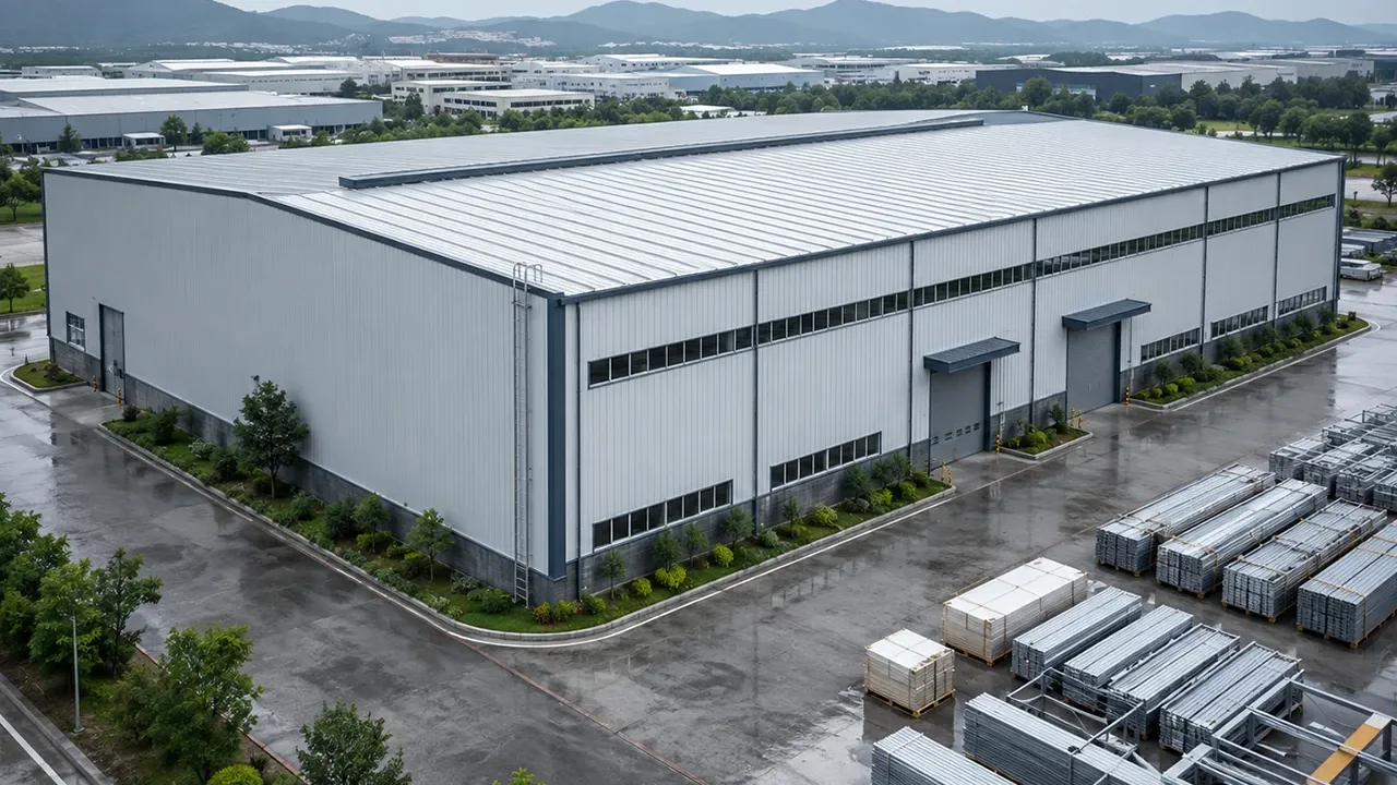
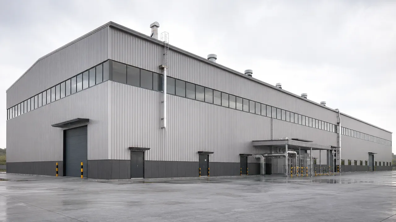
Controlled fabrication allows critical components to be cut, drilled, welded, inspected, and assembled under repeatable conditions. This is particularly valuable for moment-frame components used in a Steel structure warehouse, where repetitive rigid-frame connections must fit accurately during site erection. XTD Steel Structure combines connection detailing with controlled fabrication to improve consistency between structural design and field assembly.
Bolt Tension Capacity in Steel Structure Warehouse Frames
Rigid and portal frames used in steel warehouse buildings frequently rely on bolted moment connections at column haunches, beam splices, ridge joints, and other locations where large bending moments must be transferred. In these connections, tensile bolt forces can become significant because the moment is resisted through tension and compression forces separated across the depth of the connection.
Large spans, high wind loads, crane actions, and demanding service conditions can further increase bolt forces. Reliable warehouse-frame design therefore requires coordinated checks of bolt tension, plate bending, flange resistance, weld capacity, stiffeners, and connection geometry.
Accurate fabrication is equally important. Even a well-designed connection can become difficult to erect if bolt holes, end plates, or structural members are outside acceptable tolerances.
How Engineers Improve Bolt Tension Performance
- Select an adequate bolt diameter and strength grade.
- Optimize the arrangement of bolt rows.
- Increase end-plate stiffness where required.
- Control excessive prying action.
- Provide adequate column flange resistance.
- Add stiffeners when local forces require reinforcement.
- Check combined tension and shear loading.
- Provide sufficient weld and base metal resistance.
- Maintain accurate fabrication tolerances.
- Control bolt installation and inspection quality.
Common Design Mistakes
- Checking only the nominal tensile strength of the bolts
- Ignoring prying action
- Ignoring end-plate bending
- Ignoring column flange flexibility
- Assuming tensile forces are distributed equally among all bolts
- Ignoring combined shear and tension
- Adding more bolts without evaluating the connection geometry
- Using larger bolts while leaving surrounding plates too weak
- Ignoring fabrication and installation tolerances
- Failing to check welds and connected base metal
- Assuming bolt pretension is the same as available external tensile resistance
Frequently Asked Questions
What Is Bolt Tension Capacity?
Bolt tension capacity is the resistance of a structural bolt to axial tensile force. It depends on bolt diameter, effective tensile area, material strength, bolt grade, and applicable structural design requirements.
How Does a Moment Connection Create Bolt Tension?
A moment connection transfers bending through a combination of tension and compression forces. Bolts located in the tension zone transfer part of the tensile force between the connected members, producing axial tension in the bolts.
Does a Larger Bolt Always Increase Connection Capacity?
No. A larger bolt may provide greater tensile resistance, but the complete connection may still be controlled by end-plate bending, column flange deformation, weld strength, base metal resistance, or another limit state.
What Is Prying Action in a Bolted Connection?
Prying action is an additional force generated when a flexible plate bends and acts like a lever around the bolt. This effect increases the actual tensile force carried by the bolt.
Can Bolt Tension and Shear Occur at the Same Time?
Yes. Bolts in structural connections can experience simultaneous tension and shear. Where both actions are significant, their interaction must be considered in the design.
What Can Control a Moment Connection Before the Bolts Fail?
Possible controlling conditions include end-plate bending, column flange bending, weld failure, base metal yielding or fracture, local web behavior, prying action, or another connected component. The lowest applicable resistance governs the overall connection capacity.
Conclusion
Bolt tension capacity is a critical part of moment-connection design, but it should never be evaluated as an isolated bolt property. The actual performance of a steel-frame connection depends on how bolt forces interact with end plates, column flanges, beam flanges, welds, stiffeners, connection geometry, fabrication quality, and installation conditions.
Moment connections that control prying action, distribute bolt forces effectively, provide sufficient plate and flange stiffness, and maintain a complete load path can achieve reliable structural performance without unnecessary material or connection complexity.
The final connection should therefore be designed around the behavior of the entire system, ensuring that bolt tension resistance and all surrounding components work together to transfer moment, shear, and axial forces safely and predictably.