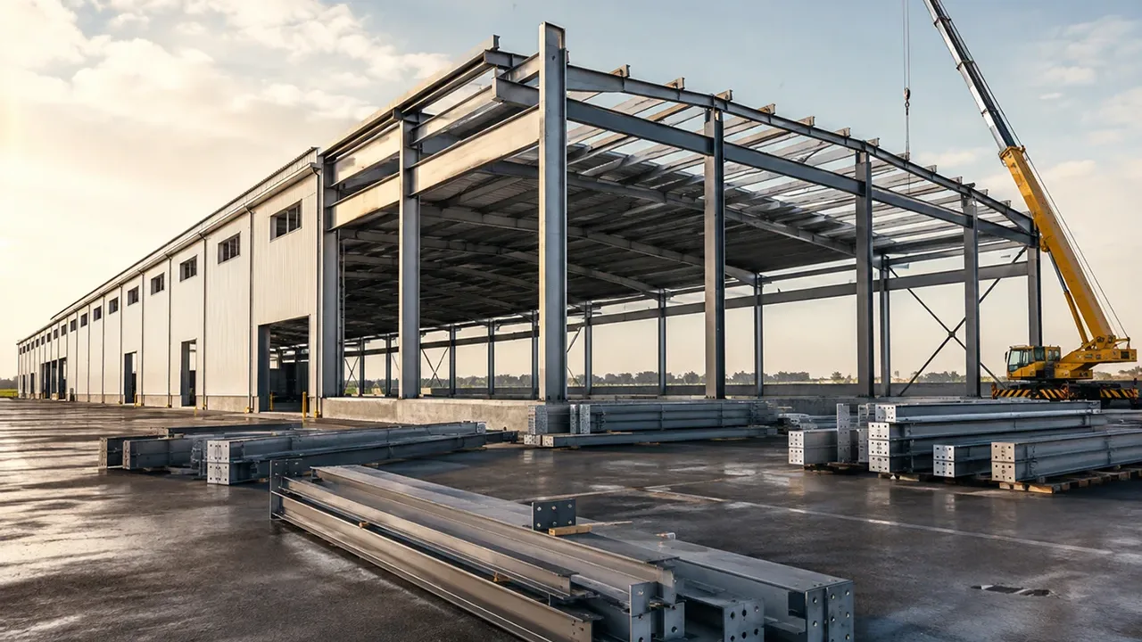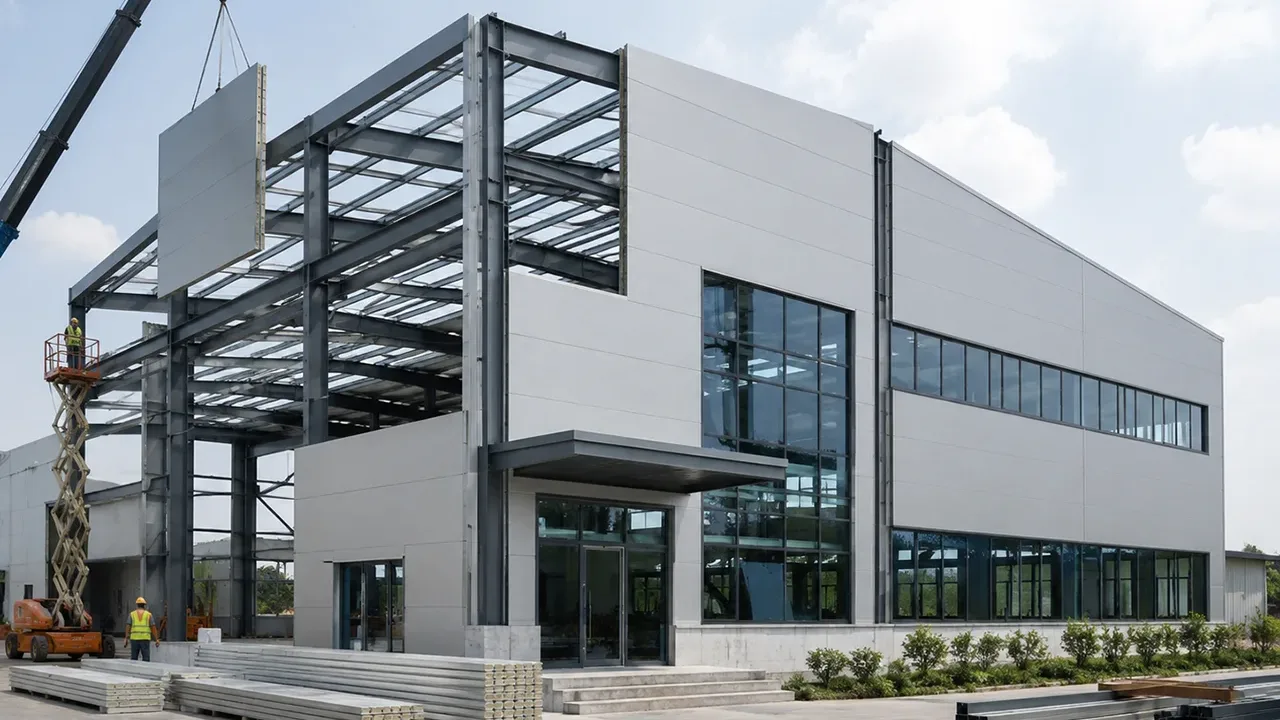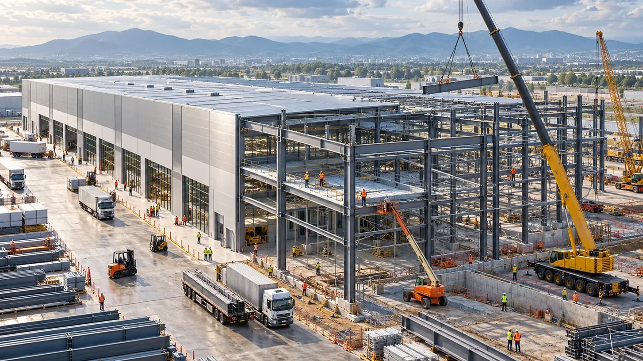
A steel roof framing system depends on many relatively small connections working together correctly. One of the most common is the connection between a secondary roof purlin and the primary rafter, roof beam, or steel truss. Although this detail may look simple on fabrication drawings, its geometry can influence load transfer, erection speed, local member behavior, and the overall reliability of the roof system.
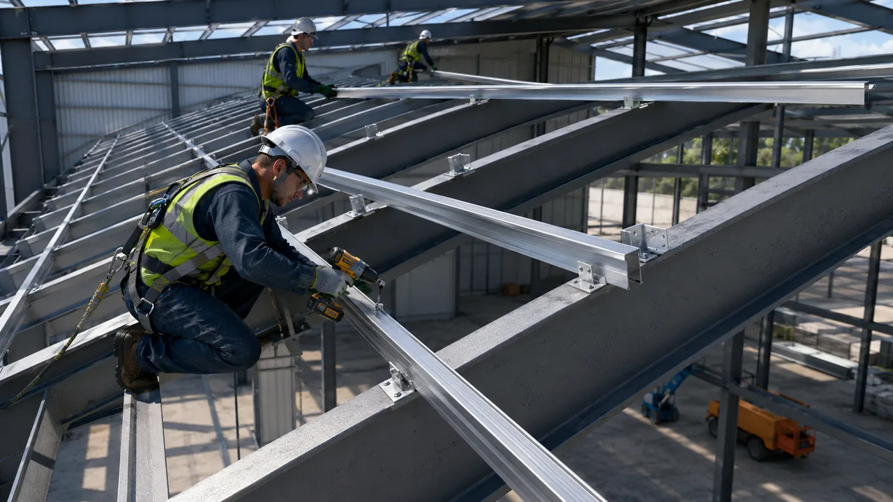
A roof purlin clip angle connection provides a practical way to attach cold-formed or structural purlins to primary steel framing. The clip angle creates a compact interface between the purlin web and its supporting member, allowing loads to move from the roof sheeting through the purlin and into the main structural frame.
Successful detailing depends on more than selecting an angle and adding several bolts. Engineers must consider gravity reactions, wind uplift, connection eccentricity, bolt spacing, purlin web strength, weld capacity, erection tolerances, corrosion protection, and access for installation.
For prefabricated steel buildings, warehouses, factories, workshops, and industrial roof systems, the connection should provide both structural capacity and practical assembly.
What Is a Roof Purlin Clip Angle Connection?
A roof purlin clip angle connection uses a steel angle to connect the web of a purlin to the supporting roof member. One leg of the angle interfaces with the purlin while the other leg is connected to the rafter, beam, or truss.
Depending on the structural system, the clip may be shop-welded to the primary frame and field-bolted to the purlin, fully bolted on both sides, or arranged as part of a specially fabricated support detail.
Basic Connection Configuration
A typical connection may include:
- A C or Z roof purlin
- A steel clip angle
- A rafter, roof beam, or truss top chord
- Structural bolts
- Shop welds where required
- Predrilled or punched holes
The clip angle generally transfers the purlin reaction through its legs, bolts, and welds into the primary frame.
The exact geometry varies with purlin depth, section orientation, support type, roof slope, design reaction, and fabrication method.
Where the Clip Angle Is Positioned
The clip angle is normally positioned beside the purlin web near the support location.
A single angle may be sufficient for many secondary framing applications. Higher loads, unusual geometry, or special stability requirements can justify paired angles or other connection arrangements.
The support face must also provide enough space for the clip, bolts, welds, and erection access. A connection that works structurally but cannot be reached with installation tools is not a practical detail.
Why Clip Angles Are Used in Steel Roof Framing
Clip angle connections are popular because they can provide:
- Simple shop fabrication
- Fast field bolting
- Repeatable connection details
- Reduced field welding
- Reasonable erection tolerances
- Compact connection geometry
- Efficient use in repetitive roof bays
These advantages can be especially useful in prefabricated steel projects where hundreds of similar purlin connections may be required.
How a Roof Purlin Clip Angle Connection Transfers Loads
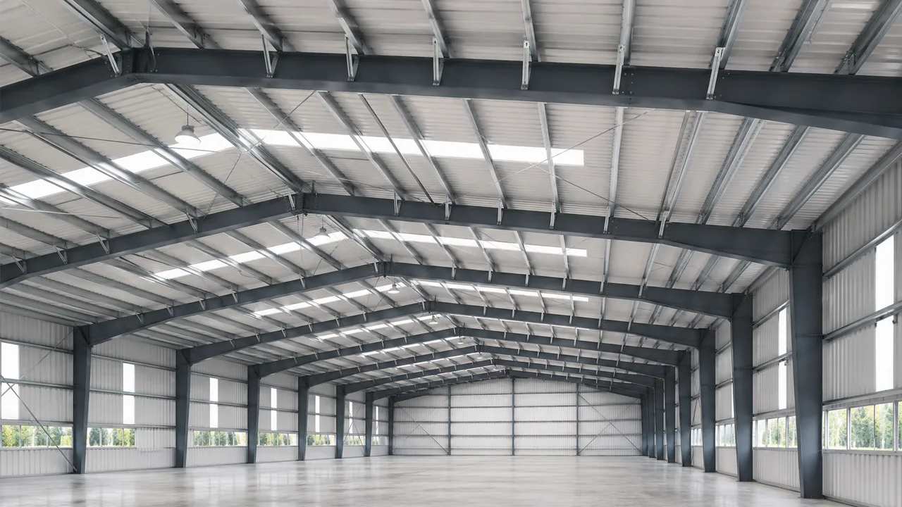
A roof purlin clip angle connection forms part of the complete roof load path. It must therefore be designed for all relevant forces rather than only the downward purlin reaction shown under one gravity load case.
Gravity Load Transfer
Under normal gravity loading, the basic load path is:
Roof sheeting → purlin → clip angle → primary frame → columns → foundation.
Roof dead load, maintenance load, rain, snow where applicable, and other downward loads are collected by the purlins.
The purlin reaction then passes through the connection by bolt shear, bearing, local plate action, weld forces, and the supporting member.
The connection should be checked as a complete system because increasing bolt capacity alone does not prevent failure in a thin purlin web or flexible clip angle.
Wind Uplift Forces
Roof connections must also resist upward forces created by wind suction.
During uplift, the load direction can partially or completely reverse compared with normal gravity loading. The bolts, angle, purlin web, welds, and primary framing attachment must therefore remain effective under the controlling uplift combination.
This is particularly important near roof edges and corners where wind effects may be more demanding.
A detail developed only from downward reaction values can be inadequate if uplift has not been included in connection design.
Axial and Secondary Forces
Purlins do not always act only as simple bending members.
Depending on the roof system, they may also participate in:
- Roof diaphragm action
- Bracing systems
- Longitudinal load transfer
- Thermal movement
- Erection stability
- Equipment support
If the structural analysis assigns axial force to the purlin, the connection must be capable of transferring that action as well.
Assumptions about purlin continuity, restraint, and bracing should therefore be consistent between structural analysis and connection detailing.
Main Components of the Connection
Each component influences the behavior of the complete connection.
Clip Angle
The clip angle must provide adequate strength and stiffness while fitting within the available geometry.
Important parameters include:
- Angle leg dimensions
- Thickness
- Steel grade
- Hole diameter
- Bolt spacing
- Edge distance
- Weld length
A very thin clip may deform excessively even when the bolts themselves have adequate capacity.
An unnecessarily heavy angle, however, can increase material use, welding demand, and fabrication cost without providing meaningful structural benefit.
Purlin
Cold-formed C and Z purlins commonly have relatively thin webs compared with hot-rolled framing.
Their connection design must therefore account for local effects around the bolt holes and support zone.
Relevant considerations include:
- Purlin depth
- Web thickness
- Section orientation
- Lip direction
- End distance
- Local bearing
- Web deformation
A strong bolt placed through a thin web does not automatically create a strong connection.
Bolts
Bolt diameter and quantity should be established from the design forces and connection geometry.
Design checks may include:
- Bolt shear
- Bearing on the connected material
- Tear-out
- Combined force effects where relevant
- Spacing requirements
- Installation access
More bolts are not always better. Poorly spaced bolts may reduce edge distances, complicate erection, or create an unnecessarily large connection.
Welded Attachment to the Primary Frame
A common fabrication strategy is to shop-weld the clip angle to the rafter or truss and then bolt the purlin in the field.
Shop welding can improve quality control because welding is performed in a controlled fabrication environment rather than at roof level.
The weld detail should consider:
- Required weld capacity
- Available weld length
- Angle thickness
- Access for welding
- Distortion control
- Inspection requirements
The weld should not simply be specified as a generic continuous weld without confirming the structural demand and fabrication implications.
Typical Roof Purlin Clip Angle Connection Details
Several arrangements can be used depending on project requirements.
Bolted Purlin to Welded Clip Angle
In this configuration, the clip angle is welded to the primary framing member during fabrication.
The purlin is then placed beside the clip on site and secured with bolts.
This arrangement can provide a good balance between controlled shop fabrication and fast field erection.
It also reduces the need for welding at height.
Fully Bolted Clip Angle Connection
Some projects use bolts to connect both the purlin and the clip to the supporting steel.
A fully bolted arrangement may provide:
- Greater field adjustability
- Reduced welding
- Replaceable components
- More modular assembly
However, sufficient space must be available for bolts, nuts, washers, and tightening equipment.
The primary frame must also be detailed with compatible holes and adequate local strength.
Single-Sided and Double-Sided Connections
A single clip angle is compact and economical for many applications.
A double-sided arrangement may be considered when the geometry or load requires improved symmetry, higher capacity, or reduced connection eccentricity.
Paired angles increase the number of components and installation operations, so they should not be used automatically where a properly designed single angle is sufficient.
Connections for C and Z Purlins
C and Z purlins require different detailing considerations because their geometry and orientation differ.
For Z purlins, the arrangement may also need to accommodate lapping over supports.
Designers should check:
- Web accessibility
- Section orientation
- Lap geometry
- Bolt interference
- Roof slope
- Clearance from flanges and lips
Connection drawings should clearly show purlin orientation to reduce erection errors.
Connection Geometry and Detailing Requirements
Small geometric details can control whether a connection performs reliably and can be assembled efficiently.
Bolt Edge Distance and Spacing
Adequate bolt spacing and edge distance help prevent local failures such as bearing damage and tear-out.
The required dimensions depend on the bolt, material, hole type, thickness, and applicable design standard.
Connections should not be compressed into an unrealistically small area simply to reduce clip size.
Purlin End Distance
Enough material must remain between the bolt hole and the purlin end.
Insufficient end distance can allow the thin web material to tear before the bolt reaches its intended capacity.
The purlin cut length must therefore be coordinated with the connection hole location.
Clip Angle Thickness
Clip thickness should be determined from structural analysis and practical fabrication requirements.
An excessively flexible angle may bend under reaction or uplift.
An excessively thick angle can require larger welds, increase material cost, and make the detail unnecessarily heavy.
Connection Eccentricity
The purlin reaction does not always pass directly through the supporting member centerline.
Offsets between the purlin web, clip, bolts, and support can introduce secondary bending or torsion.
Connection eccentricity should be recognized rather than assuming every force transfers concentrically.
Hole Tolerances and Erection Fit-Up
Prefabricated roof systems require sufficient accuracy for repeated field connections to align.
Fabrication drawings should coordinate:
- Hole positions
- Purlin cut lengths
- Clip elevations
- Roof slope
- Support geometry
- Member orientation
Slotted holes can provide adjustment where permitted by the structural design, but they should not be introduced informally during erection.
Forced alignment, uncontrolled hole enlargement, or unapproved site cutting can alter the intended connection behavior.
Structural Checks for Roof Purlin Clip Angle Connections
A complete connection should be checked for all relevant limit states.
Bolt Shear
Bolts must have adequate shear resistance for the design reaction and other transferred forces.
The number of shear planes and connection configuration should match the actual installed detail.
Bolt Bearing
Bearing stresses develop where the bolt contacts the purlin or clip material.
This may be particularly important in thin cold-formed purlin webs.
Tear-Out and Block Shear
Material around bolt holes must have enough remaining area to prevent tearing toward the free edge or failure around a group of bolts.
Correct end distance and edge distance are therefore structural requirements, not merely drafting preferences.
Clip Angle Bending
The outstanding leg of the angle may experience bending because the reaction is transferred through an offset connection.
Angle thickness and leg length should provide sufficient resistance without excessive deformation.
Weld Capacity
Where the clip is welded to the primary member, the weld should safely transfer the relevant forces.
The connected base metal must also have sufficient capacity.
Purlin Web Local Failure
Thin purlin webs can be vulnerable to:
- Local bearing
- Tear-out
- Distortion
- Local buckling
The connection must therefore be evaluated together with the purlin section rather than treating the purlin as a rigid plate.
Primary Member Local Effects
The rafter, beam, or truss supporting the clip must also be checked locally.
A connection attached to a thin web, narrow flange, or lightly reinforced truss chord may create local stresses that require additional detailing.
The capacity of a roof purlin clip angle connection is ultimately governed by its weakest relevant limit state, not simply by the nominal capacity of its bolts.
Wind Uplift and Load Reversal in Roof Connections
Wind uplift deserves specific attention because roof framing may experience force directions very different from normal gravity loading.
Why Uplift Can Control the Connection
Wind moving around a building can generate suction on roof surfaces.
This suction pulls the roof sheeting upward, and the force is transferred through fasteners into the purlins and then through their connections into the main framing.
For lightweight steel roofs, uplift can become a controlling design condition even where downward dead load reactions appear modest.
Connection Behavior Under Reversed Loading
When the reaction reverses, the connection may experience:
- Different bolt force distribution
- Clip angle deformation
- Purlin web tension and bearing changes
- Reversed weld demand
- Different support reactions
The complete load path must remain continuous under both upward and downward load combinations.
Roof Edge and Corner Zones
Wind pressures are not necessarily uniform over the entire roof.
Connections close to edges, corners, canopies, or other exposed zones may require greater capacity than connections in interior regions.
A project may therefore use several connection schedules rather than one identical clip angle throughout the entire building.
Fabrication and Installation
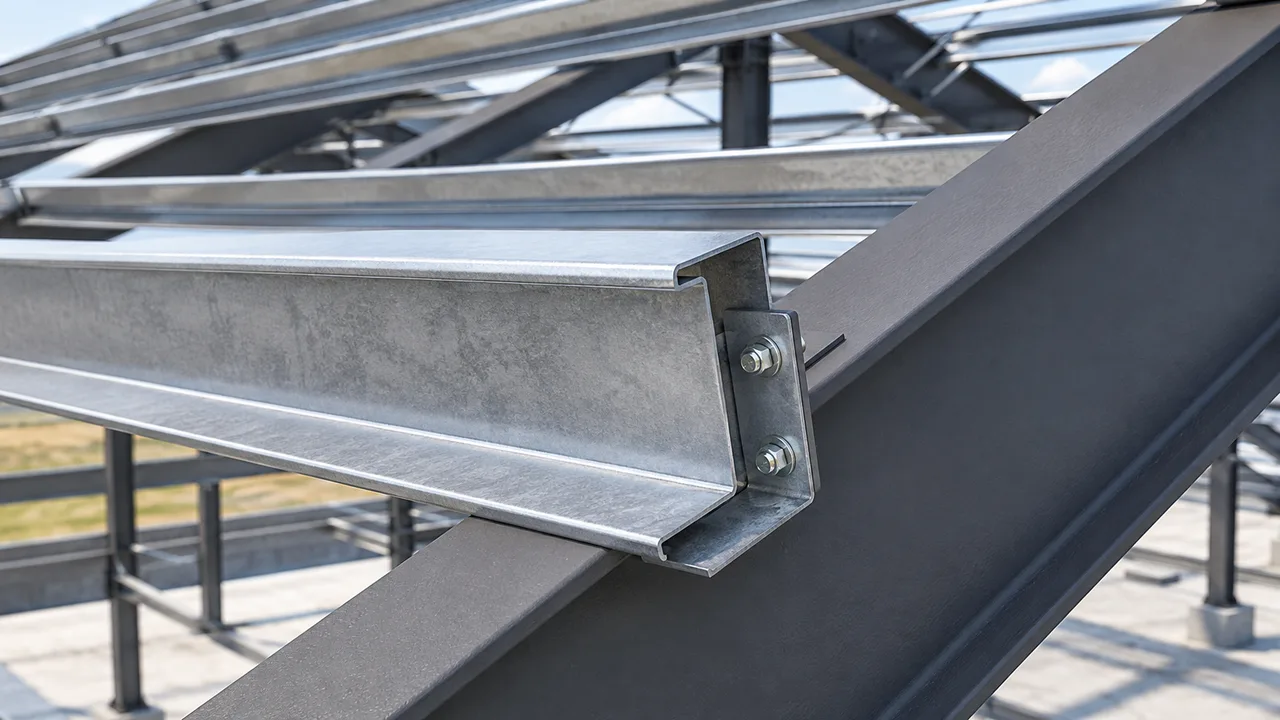
Connection design should reflect how the building will actually be fabricated, shipped, and erected.
Shop Fabrication
Typical shop operations include:
- Cutting clip angles
- Drilling or punching holes
- Welding clips to primary steel
- Checking dimensions
- Applying identification marks
- Preparing protective coatings
Repeated connection details can be produced using templates or jigs, helping maintain consistent dimensions across multiple frames.
XTD Steel Structure coordinates secondary framing connections with primary steel fabrication so that purlin attachment points can be prepared before components reach the project site.
Field Installation
A typical erection sequence may involve:
- Erecting and stabilizing the primary steel frame.
- Lifting purlins into their designated positions.
- Aligning the purlin webs with the clip angles.
- Installing the specified bolts.
- Checking roof alignment and spacing.
- Installing permanent bracing and roof sheeting.
The actual sequence depends on the structural system and approved erection method.
Why Clip Angles Can Speed Up Erection
When clips are accurately shop-installed, site crews can position purlins and complete repetitive bolted connections without extensive measuring or welding.
This can reduce work at height and improve erection productivity.
The benefit is most significant when dimensional control during fabrication is consistent.
Installation Tolerances
Site crews should not compensate for major fabrication errors by forcing members into position.
Common unacceptable shortcuts may include:
- Unapproved hole enlargement
- Missing bolts
- Forced member alignment
- Unauthorized site welding
- Cutting clips or purlins without engineering approval
Connection tolerances should be intentionally designed and shown on fabrication drawings.
Common Problems With Purlin Clip Angle Connections
Many connection problems originate from coordination and fabrication rather than from the basic structural concept.
| Problem | Possible Cause | Potential Result |
|---|---|---|
| Misaligned holes | Fabrication or setting-out error | Difficult erection and forced fit-up |
| Clip angle too thin | Connection stiffness underestimated | Excessive angle deformation |
| Insufficient edge distance | Poor bolt layout | Tear-out or local bearing failure |
| Missing bolts | Installation error | Reduced connection capacity |
| Inadequate weld | Incorrect design or fabrication | Failure at clip-to-frame attachment |
| Purlin web deformation | High concentrated reaction | Local distortion or reduced capacity |
| Incorrect purlin orientation | Unclear erection drawings | Connection misfit or structural inconsistency |
| Wind uplift ignored | Gravity-only connection design | Unsafe behavior during load reversal |
Clear drawings, connection schedules, fabrication QA, and installation inspection can eliminate many of these issues before they affect the completed roof.
Roof Purlin Clip Angle vs Bolted End-Plate Connection
The choice between a simple clip angle and other steel connection forms depends on geometry, transferred forces, fabrication requirements, and erection priorities.
A detailed comparison of roof purlin clip angle vs bolted end-plate connections can help determine which arrangement better suits a particular steel framing condition.
Connection Geometry
A clip angle typically connects beside the web of the secondary member and creates a compact side connection.
A bolted end-plate arrangement uses a plate attached at the end of the supported member and transfers forces through bolts connecting that plate to the supporting steel.
The required space and load path therefore differ.
Fabrication
Clip angles can be prepared in large repetitive batches using standard steel angles.
An end-plate connection normally requires a plate to be cut, drilled, positioned, and welded to the member end.
Neither arrangement is automatically simpler in every project. The most efficient option depends on production quantity and the geometry of the connected members.
Installation
Clip angle connections can provide convenient field bolting when bolts are accessible from the side.
End-plate connections may provide a clearly defined member-end interface but can demand tighter alignment between bolt holes.
Erection tolerance should therefore be considered before the connection type is finalized.
Structural Behavior
The two arrangements transfer loads differently.
Clip angle connections may involve eccentricity and local angle bending.
End-plate connections may transfer forces more directly through the member end but can introduce plate bending, bolt tension, and weld demand depending on the design.
One connection type should not be described as universally stronger than the other without considering the actual forces and geometry.
When Each Connection Makes More Sense
Clip angles are often practical for:
- Repetitive secondary roof framing
- Purlin-to-rafter connections
- Light or moderate secondary member reactions
- Fast field-bolted installation
Bolted end plates may be preferred where:
- Member-end geometry suits a plate connection
- A different force-transfer arrangement is required
- Connection access favors face-mounted bolts
- The structural system already uses standardized end plates
The final detail should be selected through project-specific structural and fabrication evaluation.
Clip Angle Connections for Different Steel Roof Systems
The same basic connection concept can be adapted to several steel building systems.
Portal Frame Buildings
Portal frame warehouses and factories commonly use secondary purlins spanning between rigid frame rafters.
Clip angles can provide repetitive purlin-to-rafter connections throughout the roof.
Because similar details may occur hundreds of times, standardization can significantly affect fabrication and erection efficiency.
Steel Roof Trusses
Purlins may also connect to the top chord of a steel roof truss.
Where practical, concentrated purlin reactions should be coordinated with truss panel points so that forces enter the truss near intended nodes rather than creating unnecessary local chord bending.
The clip geometry must also fit the orientation and width of the truss chord.
Large-Span Industrial Roofs
Large-span industrial roofs may have greater purlin reactions, stronger wind uplift, larger purlin sections, and more demanding service loads.
Connections may therefore require:
- Thicker clip angles
- Additional bolts
- Stronger welds
- Different connection schedules in critical roof zones
- Local reinforcement of primary framing
Standardization is still useful, but connection capacity should not be sacrificed simply to make every detail identical.
Prefabricated Steel Buildings
Prefabricated steel construction benefits from repeatable bolted connections because most fabrication can be completed before shipment.
Purlin clips can be shop-located, welded, marked, and inspected before the structural components leave the factory.
At the site, erection crews can then install pre-numbered purlins according to the coordinated assembly drawings.
This approach supports faster construction while reducing unnecessary site fabrication.
When a Roof Purlin Clip Angle Connection Is a Good Choice
A clip angle connection can be particularly suitable when:
- Secondary roof members require simple repetitive supports
- Fast erection is important
- Field welding should be minimized
- Clip angles can be prepared during shop fabrication
- Purlin reactions are compatible with the connection geometry
- Bolts are accessible for installation and inspection
- Standardization can reduce production complexity
However, the use of a clip angle should always follow structural evaluation.
Projects with very large reactions, unusual torsional demands, heavy suspended equipment, difficult support geometry, or special seismic requirements may need a different connection arrangement.
Design and Coordination Checklist Before Fabrication
Before purlin connections enter production, the project team should verify:
- Purlin type and orientation
- Purlin section thickness and depth
- Support member geometry
- Design gravity reaction
- Wind uplift reaction
- Any axial or bracing forces
- Bolt diameter and quantity
- Bolt spacing and edge distance
- Purlin end distance
- Clip angle thickness and dimensions
- Weld size and length
- Connection eccentricity
- Installation tool access
- Hole tolerances
- Corrosion protection
- Roof bracing coordination
- Roof sheeting and insulation interfaces
- Connection schedule identification
Completing this coordination before fabrication reduces field modification and helps maintain the intended structural load path.
Roof Purlin Clip Angle Connection in a Complete Steel Roof System
A roof purlin clip angle connection may occupy only a small area on a steel framing drawing, but it connects the secondary roof system directly to the primary structure.
Its performance depends on the interaction between the purlin, angle, bolts, welds, supporting steel, roof bracing, and surrounding construction.
A reliable connection therefore requires more than increasing bolt quantity. The design must consider the actual load path, gravity reactions, wind uplift, local purlin behavior, connection eccentricity, fabrication tolerances, installation access, corrosion protection, and erection sequence.
For repetitive steel buildings, careful standardization can improve both fabrication efficiency and site productivity. XTD Steel Structure integrates connection detailing with steel fabrication and project assembly so that secondary roof framing can be coordinated with the main structural system before erection begins.
When structural capacity, practical fabrication, and realistic installation conditions are considered together, clip angle connections can provide a simple, durable, and efficient solution for steel roof framing systems.