Concentrated forces can create connection problems long before the overall beam or column reaches its global strength limit. A beam flange force entering a column, a heavily loaded bracket, or a transfer connection may place very high stresses into only a small portion of a steel section. The challenge is identifying which local component is actually controlling the connection.
This is why web buckling vs flange local bending must be treated as a comparison between different structural mechanisms rather than two names for the same problem. Flange local bending develops when a concentrated force causes the flange plate itself to deform locally. Web buckling, meanwhile, refers to instability involving the web and must be interpreted according to the actual loading configuration and applicable design provision.
A good connection design therefore begins with the load path. Engineers need to determine where the force enters the section, how it spreads through the flange and web, which local limit states are applicable, and whether reinforcement is actually required. That distinction becomes particularly important in moment connections, industrial frames, transfer structures, crane-support systems, and other heavily loaded steel structures.
Why These Two Connection Limit States Are Often Confused
Both problems can appear around the same connection because both originate from highly concentrated force transfer. A beam-to-column moment connection, for example, transfers large forces from the beam flanges into the column. Those forces can require checks of the column flange, column web, welds, stiffeners, and panel zone even though all of them belong to one connection assembly.
The important point is that the presence of a concentrated force does not automatically identify the governing failure mode.
Web Buckling Is a Stability-Related Web Limit State
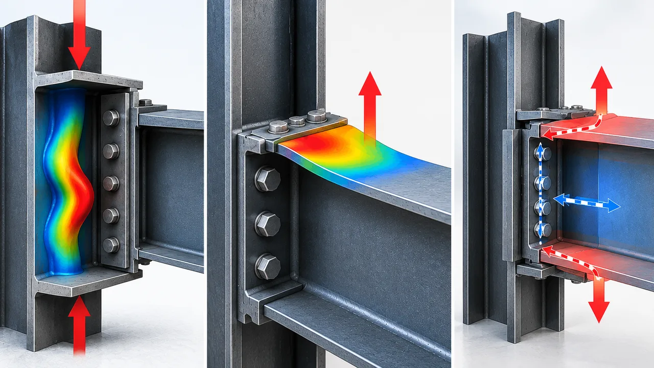
When the web is subjected to a qualifying compressive force pattern, a relatively slender web region may become unstable instead of simply continuing to carry the applied compression. The web can deform out of its plane, and its resistance depends on factors such as web thickness, clear web depth, section geometry, restraint, and the manner in which compression is introduced.
In AISC terminology, engineers should also distinguish between web compression buckling and web sidesway buckling rather than using “web buckling” as a universal label for every localized web problem.
Flange Local Bending Is a Local Plate-Bending Limit State
Flange local bending occurs when a concentrated tensile force applied through the flange causes the flange plate to bend locally around the load-transfer region. Instead of instability of the web, the critical behavior develops in the flange itself. Flange thickness, force location, section geometry, distance from the member end, and reinforcement arrangement therefore become important.
The same connection can require checks for both flange and web limit states, but passing one check does not establish that the other is safe.
Web Buckling vs Flange Local Bending at a Glance
| Design Aspect | Web Buckling | Flange Local Bending |
|---|---|---|
| Primary Component | Web | Flange |
| Basic Behavior | Instability of a web region under an applicable compression pattern | Localized bending and yielding of the flange plate |
| Force Character | Compression-controlled | Typically associated with concentrated tensile force normal to the flange |
| Important Geometry | Web thickness, web depth, restraint, flange geometry, loading configuration | Flange thickness, loaded region, distance to web and member end |
| Typical Structural Response | Out-of-plane web instability | Local flange deformation around force introduction |
| Possible Reinforcement | Stiffeners or section modification where applicable | Transverse stiffeners, continuity elements, thicker flange, or revised connection geometry |
| Main Design Question | Can the web remain stable under the applicable concentrated compression? | Can the flange transfer the force without excessive local bending? |
This comparison is useful conceptually, but engineers still need to identify the exact code-defined limit state. Under AISC provisions, concentrated-force checks are separated into several mechanisms, including flange local bending, web local yielding, web local crippling, web sidesway buckling, web compression buckling, and web panel-zone shear.
How Web Buckling Develops in Steel Connections
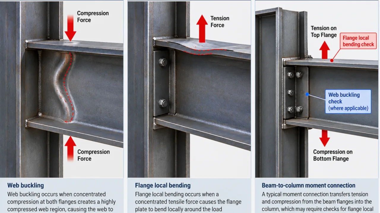
A web can carry substantial shear and axial stress under normal member behavior, but concentrated compression can create a very different local stress field. Instead of being distributed gradually over the member length, the load may enter through a relatively short region and create high compression within the web.
The exact mechanism depends on the loading arrangement. In particular, AISC web compression buckling provisions address concentrated compressive forces acting at both flanges at the same location, such as opposing compressive components that place the web between them in a highly compressed condition.
This distinction matters because a single support reaction on a beam should not automatically be classified as web compression buckling. Depending on the connection and geometry, other local web limit states such as web local yielding or web local crippling may be more relevant.
Factors That Can Increase Web Buckling Sensitivity
Several characteristics can make a web more vulnerable to instability:
- A relatively thin web compared with its clear depth
- Large concentrated compressive forces
- Limited restraint around the highly stressed web region
- A load path that introduces compression directly through opposing flange regions
- Insufficient stiffening where stiffeners are required
- Connection geometry that creates a short and highly stressed compression zone
What Web Instability Looks Like
The characteristic response is an out-of-plane distortion of the web rather than simple yielding of the material over a loaded length. That difference is fundamental. Web local yielding is a strength problem associated with material yielding, while buckling is an instability phenomenon. A connection evaluation should not combine the two simply because both occur in the web.
How Flange Local Bending Develops
When a highly concentrated tensile force is transferred through a flange, the flange cannot always be assumed to remain perfectly rigid. The force tends to bend the flange plate locally around the connection, particularly near the web where the load must eventually enter the rest of the section.
Engineers examining this behavior should perform a separate flange local bending check because the controlling mechanism lies in the flange plate rather than in web instability.
A common example is a beam flange transmitting tension into a column flange in a moment connection. The connected element pulls on a relatively localized portion of the column flange. If the flange is not sufficiently resistant, localized plate bending can develop around that region even though the column as a complete member remains adequate for axial force and flexure.
Factors That Increase Flange Local Bending Demand
- High concentrated tensile force
- Relatively thin flange
- Highly localized force-transfer area
- Connection geometry that produces severe local deformation
- Force application close to a member end
- Insufficient transverse reinforcement where reinforcement is necessary
Why Flange Thickness Has a Major Influence
Flange local bending is fundamentally a plate-bending problem, so flange thickness strongly affects resistance. This is also why simply increasing web thickness does not automatically solve a flange-bending deficiency. The reinforcement has to address the component and load path that are actually controlling the connection.
The Main Difference Is the Load Path
The clearest way to understand web buckling vs flange local bending is to trace the concentrated force through the steel section.
Load Path for Web Buckling
For an applicable web compression buckling condition, concentrated compression enters through the flanges and creates a highly compressed web region between the force introduction points. The engineering question is whether that web region has sufficient stability to remain effective under the imposed compression.
Load Path for Flange Local Bending
For flange local bending, the concentrated tensile force first acts on the flange plate. The flange must bend and distribute that force toward the web and the remainder of the section. The critical local response therefore occurs before the force is fully distributed through the member.
Two steel sections with similar overall moment or axial capacity can behave quite differently at the connection because their web thicknesses, flange thicknesses, section depths, detailing, and concentrated-force geometry may be different. Global member strength alone cannot replace local connection checks.
Where These Limit States Appear in Real Steel Connections
Beam-to-Column Moment Connections
Moment connections are one of the clearest examples of concentrated force transfer. Beam flange tension and compression must be transferred through the column flange and into the column web. Depending on the configuration, engineers may need to investigate flange local bending, web local yielding, web crippling, appropriate web buckling provisions, panel-zone shear, weld resistance, and other applicable connection limit states.
The tension side and compression side should not automatically be treated as structurally identical because the applicable local mechanisms can differ.
Transfer Members and Opposing Concentrated Compression
Transfer girders and similar framing arrangements can create large concentrated forces at matching locations on opposite flanges. These configurations are especially important when evaluating web compression buckling because they can produce a highly compressed web region between the loaded flanges.
Brackets and Heavy Equipment Connections
Industrial brackets, equipment supports, and concentrated framing connections often introduce large forces into relatively compact areas. Depending on the direction of force and connection arrangement, flange deformation, web yielding, web stability, stiffener resistance, weld strength, and local plate behavior may all need to be considered.
Crane and Heavy Industrial Structures
Crane-support systems and heavy industrial buildings frequently contain concentrated reactions and demanding connection details. The solution cannot be based only on increasing member tonnage. Proper load distribution, stiffening, fabrication access, fatigue considerations where applicable, and connection geometry can be equally important.
Design Checks Engineers Should Keep Separate
One of the biggest mistakes in concentrated-force design is treating a single successful local check as proof that the entire connection is satisfactory. Structural steel specifications divide these mechanisms because they involve different components and different structural behavior.
Evaluating Web Buckling
For a potential web stability problem, the engineer should first determine which web buckling provision actually applies. The assessment may consider the concentrated compression pattern, web depth, web thickness, flange restraint, member geometry, support conditions, and the presence of stiffeners.
For U.S.-based design, the AISC Specification for Structural Steel Buildings provides the applicable concentrated-force provisions for wide-flange and similar built-up sections. Engineers working under other design standards should use the corresponding provisions of the governing code rather than transferring AISC equations without verification.
Evaluating Flange Local Bending
The flange check focuses on the concentrated tensile force and the local bending capacity of the flange plate. Relevant parameters include flange thickness, section geometry, location of the applied force, proximity to the member end, and any transverse stiffening that participates in force transfer.
Passing One Check Does Not Mean the Connection Passes
A thick flange may provide excellent resistance to flange local bending while the adjacent web still requires reinforcement. Conversely, a robust web does not prevent a thin flange from deforming locally.
Depending on the connection, additional checks may include:
- Web local yielding
- Web local crippling
- Web sidesway buckling
- Web compression buckling
- Panel-zone shear
- Weld strength
- Bolt strength
- Connected plate yielding or rupture
- Block shear
Web Buckling vs Flange Local Bending Failure Symptoms
| Observed or Calculated Behavior | More Consistent With Web Buckling | More Consistent With Flange Local Bending |
|---|---|---|
| Out-of-plane distortion concentrated in the web | Yes | No |
| Localized curvature of the flange plate | No | Yes |
| Behavior controlled by web slenderness and restraint | Yes | Usually no |
| Behavior highly sensitive to flange thickness | Indirectly | Yes |
| Instability is the primary mechanism | Yes | No |
| Local plate bending around a concentrated tensile force | No | Yes |
These observations are useful for understanding behavior, but visual appearance alone should never replace structural analysis. Local limit states can interact, and permanent deformation observed after loading may reflect more than one mechanism.
How to Reduce Web Buckling Risk
Increase Web Resistance Where Appropriate
A section with a thicker web or more favorable web proportions can improve local stability. However, selecting a substantially heavier rolled section solely to solve a short localized deficiency may not always be the most economical solution.
Use Properly Designed Transverse Stiffeners
Stiffeners can provide a more direct force-transfer path and increase resistance around the concentrated-force region. Their geometry, welds, contact conditions, and connection to the flanges and web must be designed as part of the load path rather than added as an isolated plate.
Review the Force Introduction Detail
Changing where and how compression enters the section may reduce local demand. In some connections, modifying the supporting plate, connection geometry, or stiffener arrangement can be more efficient than simply increasing the member size.
How to Reduce Flange Local Bending
Select a Flange With Greater Local Resistance
A thicker flange provides greater resistance to localized plate bending. This may be achieved by selecting a different rolled section or, in a fabricated member, adjusting the flange plate thickness where structurally and economically appropriate.
Add Transverse Reinforcement
Properly designed stiffeners or continuity elements can help transfer concentrated flange forces more directly into the web and reduce reliance on local flange bending. The reinforcement itself, including welds and supporting elements, must also be checked for the transferred force.
Improve Connection Geometry
A more favorable connection layout can distribute force more effectively and reduce severe local deformation. Connection redesign may sometimes provide a cleaner solution than repeatedly increasing individual plate thicknesses.
When Stiffeners Become the Better Solution
A member can be perfectly adequate for its overall axial, shear, and flexural demands while failing a localized concentrated-force check at one connection. In that situation, increasing the size of the entire beam or column can add substantial steel weight simply to strengthen a very short region.
Localized reinforcement can therefore be efficient when:
- The main member has adequate global strength
- The deficiency is limited to one or several connection zones
- Concentrated forces are significantly higher than surrounding member forces
- A practical stiffener can create a clearer load path
- Moving to the next suitable rolled section would create excessive weight or cost
Stiffeners are not automatically the cheapest answer, however. They require plate cutting, fitting, welding, inspection, and adequate shop or field access. A heavier unstiffened member can sometimes be more economical after fabrication labor is considered.
Connection Design Should Consider Fabrication and Erection
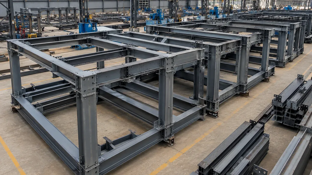
A connection detail that works mathematically still has to be manufactured and installed. Closely spaced stiffeners may restrict welding access. Intersecting plates can create difficult weld sequences. Reinforcement may interfere with bolts, secondary framing, decking, piping, equipment, or erection clearances.
Fabrication considerations should therefore be addressed while the load path is being developed rather than after the connection drawings are completed. Plate dimensions, weld access, inspection requirements, dimensional tolerances, shop welding, field welding, and erection sequencing can all influence the most practical reinforcement solution.
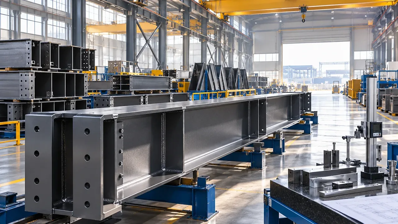
For industrial and prefabricated steel structures, XTD Steel Structure coordinates engineering requirements with detailing, fabrication, and erection planning so connection reinforcement can be incorporated into the structure without creating unnecessary shop or site conflicts.
This coordination is particularly useful for projects containing heavy equipment, crane systems, transfer framing, large-span structures, or repeated moment connections where the same concentrated-force detail may occur many times.
Choosing the Right Response to the Governing Limit State
The practical value of understanding web buckling vs flange local bending is that each mechanism leads to a different engineering response.
If the web is unstable: review the actual web buckling mechanism, web proportions, restraint, concentrated compression arrangement, and potential stiffening.
If the flange is bending locally: focus on flange thickness, concentrated tensile force transfer, connection geometry, and suitable transverse reinforcement.
If several local checks are close to their limits: reconsider the complete load path. Solving each deficiency with an additional plate may produce a complicated connection when a different member size or connection configuration would be simpler.
If the member is also highly utilized globally: selecting a larger section may provide a more rational solution than adding extensive local reinforcement.
The objective is not to maximize the amount of steel around the connection. It is to provide sufficient resistance to each applicable limit state through a clear, buildable, and inspectable load path.
Practical Concentrated-Force Connection Checklist
Before finalizing a heavily loaded steel connection, the design team should confirm the following:
- Identify the magnitude and direction of each concentrated force.
- Trace how each force enters the flange and web.
- Determine whether the force is tensile, compressive, or part of an opposing force pair.
- Check flange local bending where applicable.
- Check web local yielding and web crippling where applicable.
- Determine whether web sidesway buckling or web compression buckling applies.
- Check panel-zone behavior in moment connections where required.
- Verify stiffeners and continuity elements as structural components.
- Check welds, bolts, and connected plates independently.
- Consider all governing load combinations.
- Confirm adequate fabrication and inspection access.
- Consider erection tolerances and field connection requirements.
- Use the requirements of the governing structural design standard.
Frequently Asked Questions
What Is the Main Difference Between Web Buckling and Flange Local Bending?
Web buckling is a stability-related response involving the web under an applicable compressive loading condition. Flange local bending is localized bending of the flange plate caused by concentrated force transfer, commonly associated with a concentrated tensile force normal to the flange. They affect different parts of the section and require separate design checks.
Can Web Buckling and Flange Local Bending Occur in the Same Connection?
Yes. One connection can produce several local demands simultaneously. A moment connection, for example, can require checks of the column flange, column web, panel zone, welds, bolts, and reinforcement. The applicable limit states depend on the direction and arrangement of the forces.
Does a Thicker Web Prevent Flange Local Bending?
No. Increasing web thickness may improve certain web limit states, but flange local bending is controlled primarily by the flange and its local force-transfer geometry. A connection should be strengthened according to the component that governs.
Do Stiffeners Prevent Both Failure Modes?
Not automatically. Properly configured stiffeners can significantly change the load path and improve several local limit states, but their effectiveness depends on their position, dimensions, welds, connection to adjacent elements, and the actual force being transferred.
Is Web Buckling the Same as Web Local Yielding?
No. Web local yielding is associated with yielding of the web material under concentrated force, while web buckling is an instability phenomenon. Because the mechanisms differ, the governing equations, relevant geometry, and possible reinforcement strategies also differ.
When Should a Larger Steel Section Be Used Instead of Stiffeners?
A larger section can be preferable when several local limit states are deficient, when the main member is already highly utilized, or when the labor and inspection associated with extensive reinforcement exceed the cost of additional member weight. The decision should consider material, fabrication, transportation, erection, and lifecycle requirements rather than steel tonnage alone.
Matching the Connection Detail to the Actual Failure Mode
The essential lesson from web buckling vs flange local bending is that similar-looking concentrated-force problems can originate from very different structural mechanisms. Flange local bending concerns localized deformation of the flange plate, while web buckling concerns instability within the web under specific compressive loading conditions.
Engineers should identify the load path first, determine which code-defined limit states apply, and then reinforce the actual governing component. Web thickness, flange thickness, stiffeners, continuity elements, and larger member sections are all potential tools, but none is universally correct.
For fabricated industrial structures, connection design should also remain compatible with plate processing, welding access, inspection, transportation, and erection. By integrating these considerations early, XTD Steel Structure can help turn concentrated-force connection requirements into practical details that perform reliably both on the calculation sheet and in the completed structure.