Bolted connections are widely used in structural steel construction because they provide reliable load transfer, efficient site erection, and straightforward inspection. In beam connections and end-plate systems, one of the most important design checks is bolt shear capacity, which determines how much transverse force a bolt or bolt group can safely resist before shear failure occurs.
However, bolt strength alone does not determine the capacity of the complete connection. Plate bearing, bolt tension, edge distance, bolt-hole geometry, end-plate thickness, connected-member strength, and the overall load path can all control the final resistance. Engineers therefore evaluate bolt shear together with the surrounding connection components to achieve predictable structural performance.
What Is Bolt Shear Capacity?
Basic Definition of Bolt Shear Capacity
Bolt shear capacity is the amount of shear force a structural bolt can safely resist across one or more shear planes. Shear occurs when connected components attempt to slide relative to each other and the bolt resists that movement across its cross-section. The available resistance depends on the bolt diameter, material strength, number of shear planes, position of the threads, and applicable structural design requirements.
A high bolt shear resistance does not automatically mean that the connection has equally high capacity. The connected plate, bolt holes, end plate, beam, column flange, or other structural components may reach their own limit states first.
How Shear Force Acts on Structural Bolts
When a beam transfers vertical reaction into a supporting column or structural member, the connection components transmit that force into the bolt group. The bolts resist relative movement between the connected plates. In a bearing-type connection, the bolt shank eventually contacts the side of the bolt hole, allowing shear force to transfer through the bolt and into the supporting plate.
Single Shear vs Double Shear
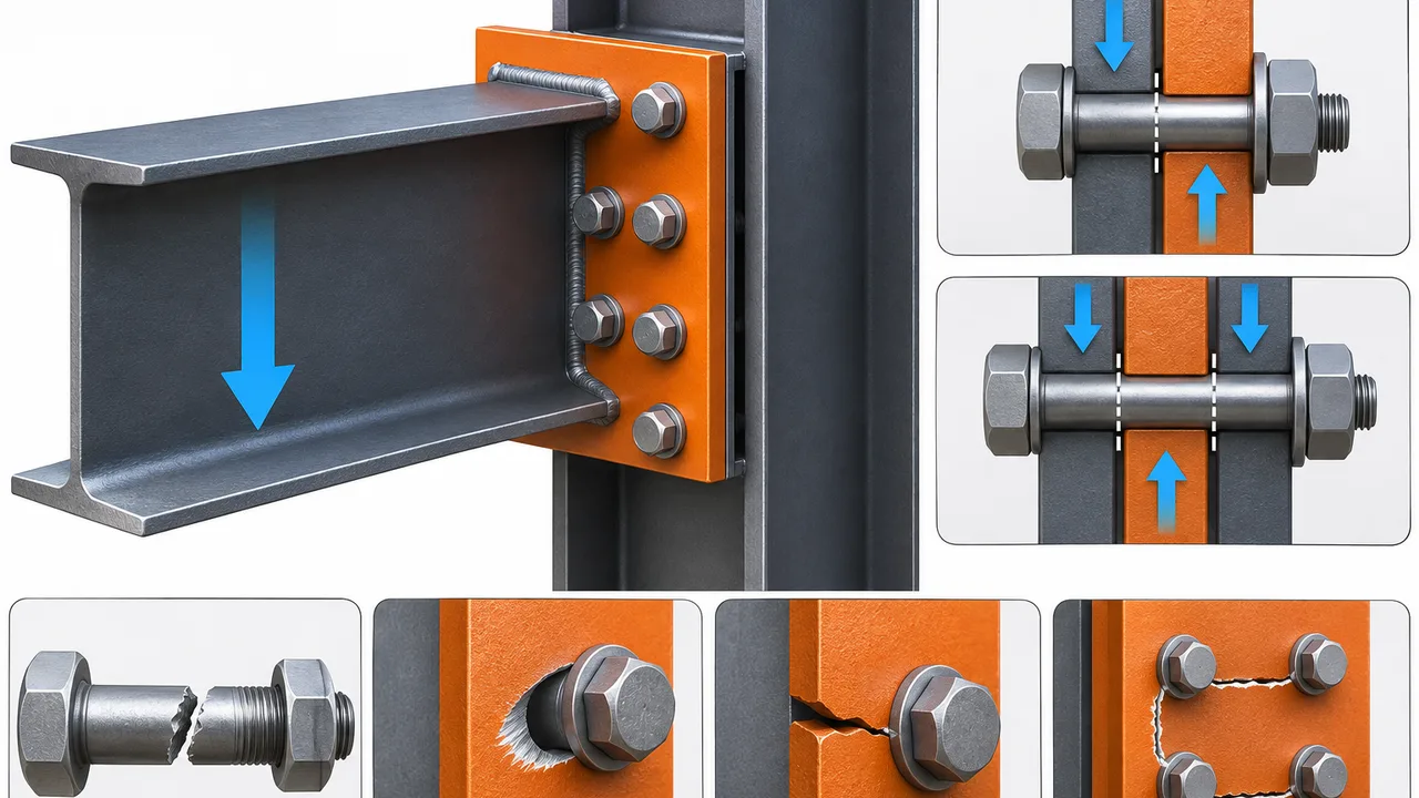
A bolt in single shear has one primary shear plane, while a bolt in double shear has two. Because the shear force can be resisted across more than one plane, a double-shear arrangement can generally provide greater total shear resistance than a comparable single-shear arrangement. The actual design capacity still depends on bolt geometry, material strength, and the surrounding plates.
How Bolts Transfer Shear in Steel Connections
Bearing-Type Bolted Connections
In a bearing-type connection, force is transferred when the bolt shank bears against the side of the bolt hole. The bolt develops shear resistance while the connected plate develops bearing resistance. This means that bolt shear and plate bearing must be checked together because failure can occur in either component.
Slip-Critical Connections
Slip-critical connections use pretensioned bolts and friction between prepared contact surfaces to transfer load before significant slip occurs. The design consideration is different from a conventional bearing-type connection because slip resistance may govern under service conditions. After sufficient slip, other limit states such as bolt shear and plate bearing may become relevant depending on the connection design.
Complete Load Path Through the Connection
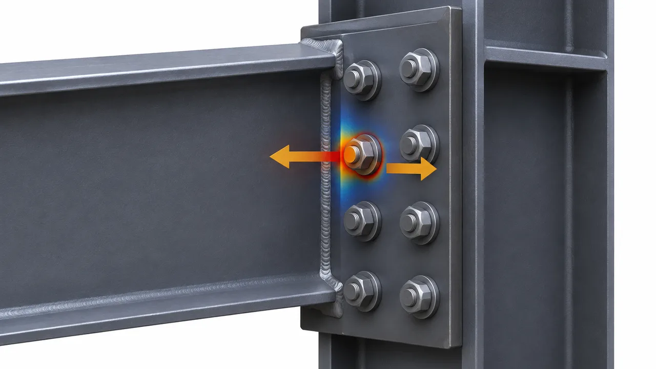
A beam connection transfers forces through a sequence of components. In a typical bolted end-plate connection, the beam transfers load into the welded end plate, the end plate transfers force into the bolts, and the bolts transfer the load into the column flange or supporting member. Every component in this load path must provide sufficient resistance.
Bolt Shear Capacity in Beam Connections
Simple Shear Connections
Simple shear connections are designed primarily to transfer beam reactions while allowing relatively small rotational restraint. Common arrangements include shear tabs, fin plates, and double-angle connections. The bolts usually carry significant shear, making bolt shear capacity an important design consideration.
Beam End-Plate Connections
In a beam end-plate connection, the end plate is normally welded to the beam and bolted to the supporting column or structural member. Vertical shear from the beam is transferred through the end plate into the bolt group. Bolt arrangement, plate thickness, hole dimensions, and connection geometry influence how these forces are distributed.
Moment End-Plate Connections
Moment end-plate connections transfer bending moments in addition to shear. Bolts positioned near the beam flanges may experience substantial tensile forces while the connection also carries vertical shear. In this situation, bolt shear cannot always be evaluated independently because combined shear and tension may influence the available resistance.
Factors That Determine Bolt Shear Capacity
Bolt Diameter
Larger-diameter bolts generally provide greater shear area and therefore greater potential shear resistance. However, using a larger bolt may also require larger bolt holes, greater spacing, and larger connection plates.
Bolt Grade and Material Strength
Higher-strength structural bolts can generally resist greater shear forces than lower-strength bolts of the same diameter. The selected grade must be compatible with the structural design, installation method, and applicable project requirements.
Number of Bolts
Increasing the number of bolts can increase the total resistance of a bolt group. In simple concentric connections, the shear may be approximately distributed among the bolts, but real connections may experience uneven loading due to eccentricity, deformation, and stiffness differences.
Number of Shear Planes
The number of shear planes directly influences available resistance. A bolt in double shear can resist force across two planes, while a bolt in single shear has only one primary plane.
Threads in the Shear Plane
If the threaded portion of the bolt crosses the shear plane, the effective cross-sectional area resisting shear may be lower than when the unthreaded shank lies in the shear plane. This distinction can affect the calculated resistance.
Bolt Hole Type
Standard holes, oversized holes, and slotted holes can produce different connection behavior. Hole geometry influences slip, bearing, installation tolerance, and the applicable design checks.
Bolt Group Behavior Under Shear
Direct Shear Distribution
For a concentrically loaded bolt group with relatively uniform geometry, engineers may approximate the direct shear force as being distributed among the bolts. If a connection carries a total shear force through several identical bolts, each bolt contributes to the total group resistance.
Eccentric Shear
When the applied force does not pass through the centroid of the bolt group, the connection experiences direct shear together with an additional moment. This moment can significantly increase the demand on certain bolts.
Uneven Load Distribution
Bolt forces are not always perfectly equal. Plate flexibility, bolt spacing, connection geometry, deformation, and eccentricity can cause some bolts to carry more load than others.
Critical Bolt in a Bolt Group
In an eccentrically loaded connection, the bolt located farthest from the bolt-group centroid may experience higher demand due to the additional rotational effect. Engineers therefore evaluate the bolt group rather than assuming that every bolt carries exactly the same force.
Bolt Shear and Combined Loading
Combined Shear and Tension
Structural bolts can experience shear and tension simultaneously. This condition is common in moment end-plate connections, flange connections, brackets, and connections subjected to eccentric loading. When both actions occur, the available resistance must be checked using the applicable interaction requirements.
Prying Action
Prying action can develop when flexible plates deform and create additional tensile forces in the bolts. Although prying primarily increases bolt tension, it can become important in a connection that already carries significant shear.
Interaction Between Bolt Shear and Bolt Tension
A bolt that is heavily loaded in tension may have less available resistance for additional shear, depending on the design method and structural code. Engineers therefore should not evaluate bolt shear capacity in isolation when significant tensile forces are also present.
Other Limit States That Can Control Before Bolt Shear
Plate Bearing Failure
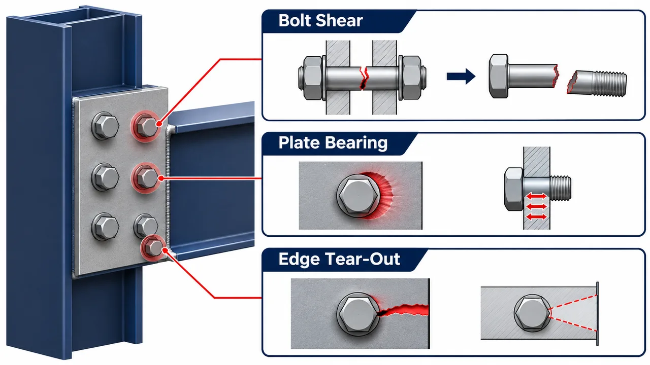
Bearing failure occurs when high local pressure between the bolt and the side of the bolt hole deforms the connected plate. Thin plates, high bolt forces, and limited edge distances can increase this risk.
Edge Tear-Out
If a bolt is positioned too close to the plate edge, the material between the hole and the edge may tear out before the bolt reaches its full shear capacity.
Net-Section Fracture
Bolt holes reduce the net cross-sectional area of the connected plate. A line of holes can create a critical fracture path if the remaining steel area is insufficient.
Block Shear Failure
Block shear combines shear and tensile failure around a bolt group. Bolt arrangement, plate geometry, edge distance, and material strength all influence this limit state.
End-Plate Bending
A flexible end plate can deform significantly under loading. Excessive plate deformation can redistribute forces among the bolts, increase bolt tension, and influence overall connection behavior.
Supporting Member Failure
The supporting column flange, column web, beam flange, beam web, or other connected member may govern before the bolts reach their maximum resistance. Connection design must therefore include all surrounding structural components.
Bolt Shear Capacity vs Plate Bearing Capacity
Bolt shear capacity and plate bearing capacity represent different failure mechanisms. Bolt shear involves failure through the bolt cross-section, while plate bearing involves local deformation or failure around the bolt hole. Both checks are essential because increasing bolt strength does not automatically increase connection capacity if the connected plate remains relatively thin.
A high-strength bolt can still be part of a connection governed by plate bearing, edge tear-out, net-section fracture, or block shear. Plate thickness, bolt diameter, hole size, bolt spacing, and edge distance must therefore be coordinated with the selected bolt resistance.
Bolt Shear Capacity in Bolted End-Plate Connections
Load Transfer Through the End Plate
In an end-plate connection, beam forces first enter the end plate through the welded beam-to-plate interface. The end plate then transfers those forces into the bolts and finally into the supporting column or structural member.
Bolt Arrangement
The number of bolt rows, bolt spacing, edge distances, and position relative to the beam web and flanges influence load distribution. A well-proportioned bolt group helps distribute the connection forces efficiently and provides sufficient space for fabrication and installation.
End-Plate Thickness
End-plate thickness influences connection stiffness and deformation. A thin end plate may bend significantly, while a thicker plate can provide greater stiffness but may increase material use and welding requirements.
Column Flange Behavior
The supporting column flange may also deform under bolt forces. Local flange bending can influence bolt tension and connection stiffness, especially in moment-resisting end-plate connections.
Typical Bolt Shear Failure Modes
Shear Fracture Through the Bolt Shank
Bolt shear fracture can occur when the applied shear exceeds the available resistance of the bolt cross-section.
Shear Through the Threaded Portion
When the threaded portion lies in the shear plane, the reduced effective area may decrease the available shear resistance compared with a shear plane through the full bolt shank.
Multiple-Bolt Group Failure
A bolt group can become inadequate when the total applied shear exceeds the combined resistance of the bolts or when uneven force distribution causes one or more critical bolts to become overloaded.
Progressive Local Connection Failure
Local plate deformation, bolt-hole elongation, or failure of one connection component can redistribute forces to other bolts. This redistribution may increase demand on the remaining connection elements.
Bolted Connection Design Comparison
| Factor | Influence on Bolt Shear Capacity |
|---|---|
| Bolt diameter | Larger diameter generally increases capacity |
| Bolt grade | Higher-strength material generally increases resistance |
| Number of bolts | More bolts can increase total group capacity |
| Shear planes | More shear planes generally increase resistance |
| Threads in shear plane | May reduce effective shear resistance |
| Plate thickness | Influences bearing and tear-out resistance |
| Edge distance | Affects plate failure resistance |
| Bolt spacing | Influences load distribution and plate behavior |
| Hole type | Can affect slip, bearing, and installation behavior |
| Combined tension | Can reduce available bolt shear resistance |
Fabrication and Installation Considerations
Accurate Hole Positioning
Bolt holes must be positioned accurately so connected members can be assembled without forcing or excessive modification. Poor alignment can delay erection and create unintended stresses or installation problems.
Bolt Installation Quality
The correct bolt grade, washers, tightening method, and pretension must be used where required. Installation quality directly influences connection reliability, especially in pretensioned and slip-critical joints.
End-Plate Fabrication Accuracy
End plates require accurate dimensions, proper flatness, correct bolt-hole locations, and controlled welding distortion. Poor fabrication tolerances can make field assembly difficult and affect connection fit-up.
Factory Quality Control
A well-managed Steel structure factory can control bolt-hole positioning, end-plate fabrication, welding procedures, dimensional tolerances, and inspection before the components reach the construction site. XTD Steel Structure integrates connection detailing with controlled fabrication processes to help maintain consistent geometry and reliable field assembly.
How Engineers Check Bolt Shear Capacity
A systematic connection design normally includes the following steps:
- Determine the design forces acting on the connection.
- Identify the total shear force that must be transferred.
- Determine the number and arrangement of bolts.
- Identify the number of shear planes.
- Check whether bolt threads cross the shear plane.
- Determine the nominal bolt shear resistance.
- Apply the required design or resistance factors.
- Check combined shear and tension where applicable.
- Check plate bearing resistance.
- Check edge tear-out resistance.
- Check net-section fracture.
- Check block shear resistance.
- Check the end plate and supporting-member capacity.
- Confirm fabrication and installation requirements.
This process demonstrates why bolt shear capacity should always be evaluated as part of the complete structural connection rather than as an isolated bolt property.
Common Bolt Shear Design Mistakes
- Checking only the shear resistance of the bolts
- Ignoring plate bearing capacity
- Providing insufficient bolt edge distance
- Assuming equal bolt forces under eccentric loading
- Ignoring threads located in the shear plane
- Using too few bolts for the applied connection forces
- Ignoring combined shear and tension
- Ignoring end-plate flexibility
- Ignoring column flange deformation
- Using incorrect bolt-hole dimensions
- Allowing poor fabrication tolerances
- Installing the wrong bolt grade during erection
Bolt Shear Capacity for Different Structural Applications
Industrial Steel Buildings
Industrial steel structures commonly use bolted beam-column connections, equipment-support connections, and bracing systems. Connection design may need to consider machinery loads, vibration, repetitive loading, and erection efficiency.
Steel Warehouses
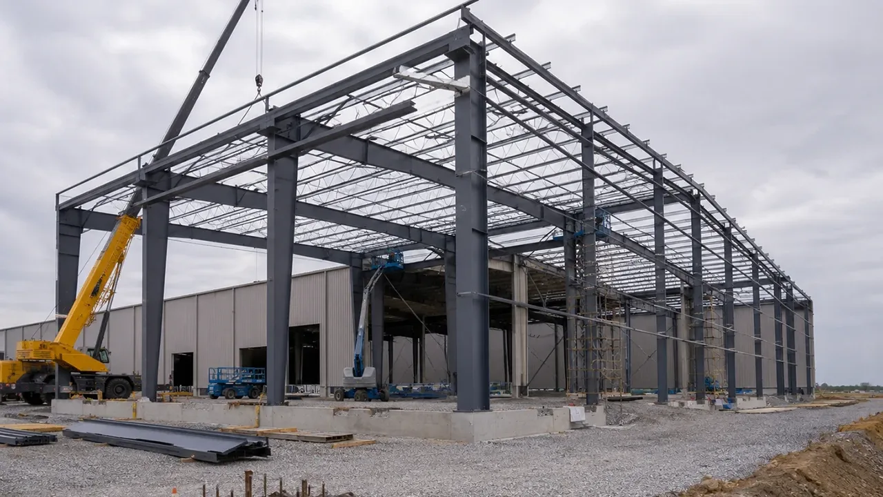
Steel warehouses commonly use portal frames and prefabricated structural components. Bolted site connections allow efficient erection while minimizing field welding.
Steel Factories
Factory buildings may include crane systems, heavy equipment, and repetitive industrial loads. Bolt groups must be designed for the actual combination of shear, tension, and other connection forces.
Steel Trusses
Truss connections frequently use bolts at gusset plates, chords, and web members. Connection geometry and bolt-group arrangement strongly influence force transfer.
Bridges and Infrastructure
Bridge and infrastructure connections may require high-strength bolts, fatigue-resistant detailing, strict installation procedures, and accessible inspection arrangements.
Frequently Asked Questions
What Determines Bolt Shear Capacity?
Bolt shear capacity depends primarily on bolt diameter, bolt grade, number of shear planes, whether the threads are included in the shear plane, and the applicable structural design requirements.
Does a Larger Bolt Always Have Higher Shear Capacity?
A larger bolt generally has greater shear area and therefore greater potential shear resistance, but the complete connection may still be controlled by plate bearing, tear-out, net-section fracture, block shear, or another structural component.
What Is the Difference Between Single Shear and Double Shear?
Single shear involves one primary shear plane through the bolt, while double shear involves two. A double-shear configuration can generally provide greater total shear resistance when the surrounding components are also adequate.
Can Bolt Shear and Tension Occur at the Same Time?
Yes. Combined shear and tension are common in end-plate connections, moment connections, brackets, and eccentric connections. Both actions must be evaluated together where required.
Can Plate Bearing Control Before Bolt Shear?
Yes. Plate bearing can govern when the connected plate is relatively thin, bolt forces are high, edge distances are limited, or the bolt arrangement produces high local pressures around the holes.
Why Are End-Plate Connections Often Bolted on Site?
Bolted end-plate connections allow prefabricated members to be assembled quickly on site, reduce field welding, simplify alignment, and provide practical inspection and adjustment during erection.
Conclusion
Bolt shear capacity is an essential part of steel connection design, but it should never be treated as the only measure of connection strength. Reliable beam and end-plate connections also require checks for bolt tension, plate bearing, edge tear-out, net-section fracture, block shear, end-plate deformation, and the resistance of the supporting members.
The most effective connection is not necessarily the one using the strongest individual bolt. It is the connection in which the bolts, plates, welds, beam, column, and surrounding components work together to provide a clear and predictable load path.
By balancing structural resistance, fabrication quality, installation practicality, inspection requirements, and overall project efficiency, engineers can develop beam and end-plate connections that provide reliable long-term performance.