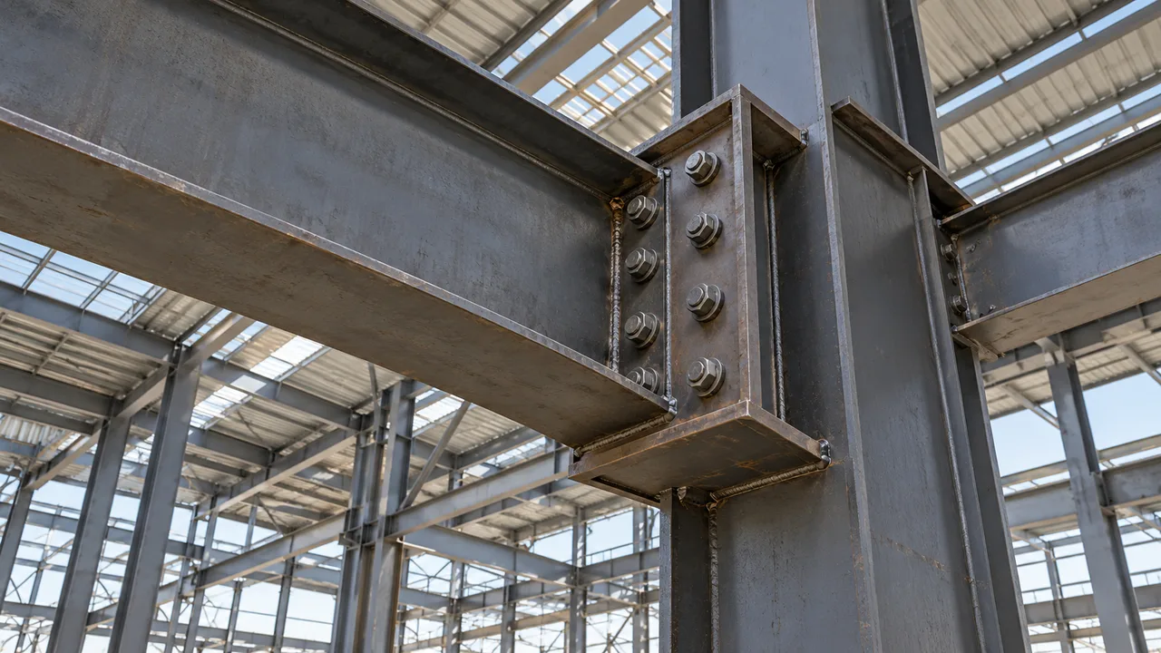
Moment connections transfer substantial forces through relatively compact regions of steel. In an end-plate connection, tension from the beam flange passes through the weld, end plate, bolts, and supporting flange before entering the rest of the structural system. Each component contributes stiffness and resistance, and changing one component can alter how the others respond.
The relationship between end-plate thickness and flange local bending is therefore important in the design of steel moment connections. A thinner plate can deform more readily around bolt rows, while a thicker plate provides greater stiffness and generally changes the distribution of tension forces. However, increasing plate thickness does not automatically eliminate local bending in the supporting flange.
Reliable connection design requires the end plate, bolts, welds, supporting flange, web, and any reinforcement to be evaluated as parts of one continuous load path.
Why End-Plate Thickness Matters in Moment Connections
The end plate forms a critical part of the force-transfer mechanism in a bolted end-plate connection. When beam moment develops tension in one flange and compression in the opposite flange, the tensile force must pass through the end plate and bolt group into the supporting member.
The plate is not perfectly rigid. It can bend between the beam flange, bolt rows, and plate edges. Its thickness therefore influences connection stiffness, local deformation, bolt force distribution, and the tendency for additional prying forces to develop.
A relatively thin end plate may undergo noticeable deformation before the supporting flange reaches its full local resistance. A thicker plate generally reduces plate flexibility and allows the tensile force to be transmitted more directly through the bolts. The resulting force pattern may then place a larger proportion of the demand on the supporting flange itself.
For this reason, end-plate thickness should not be selected independently from the supporting member geometry.
How End-Plate Thickness Influences Flange Local Bending

Thin End Plates Allow Greater Plate Deformation
A thin plate has lower bending stiffness and can deform around the bolt rows as tensile forces develop. This deformation changes the geometry of the connection under load and may cause the force distribution among bolts to differ from a simple rigid-plate assumption.
Greater plate deformation can also increase separation tendencies between the plate and the supporting flange. Once this occurs, secondary forces associated with prying action may increase bolt tension and modify the local demand transferred to the supporting flange.
The actual behavior depends on bolt spacing, plate projection, beam flange force, weld geometry, and supporting flange stiffness.
Thicker End Plates Increase Connection Stiffness
Increasing plate thickness raises the bending stiffness of the end plate. The plate deforms less under the same tensile demand, and the connection generally develops a more direct load path between the beam flange, bolts, and supporting flange.
Reduced plate deformation can decrease some forms of prying action and improve rotational stiffness. However, the higher stiffness can also shift the controlling limit state away from plate bending and toward the bolts, welds, supporting flange, web, or reinforcement.
A thicker plate therefore changes the connection response rather than simply making every component safer.
Increasing Thickness Does Not Eliminate Flange Local Bending
One of the most important points in evaluating end-plate thickness and flange local bending is that plate thickness and supporting flange strength are separate design issues.
Even a very thick end plate cannot compensate for an inadequately sized supporting flange. The flange may still bend locally around the tension bolt rows if its thickness, effective width, or support conditions are insufficient for the applied force.
Bolt gauge, bolt-row spacing, column flange thickness, beam flange force, and continuity reinforcement may all influence the flange local bending check.
Load Path Between the End Plate, Bolts, and Supporting Flange
The connection behavior becomes easier to understand when the load path is considered step by step.
Beam moment first creates tension and compression forces in the beam flanges. The tensile flange force is transferred through the beam-to-end-plate weld. The end plate then distributes this force toward the tension bolt rows.
As the end plate bends, the bolts develop tension and transmit the force into the supporting member. The supporting flange experiences local bending around the bolt locations before the force continues into the column web, panel zone, or surrounding structural system.
Every component affects the next one. A flexible end plate can increase deformation and prying effects, while a stiff end plate can transfer force more directly to the supporting flange.
This is why local connection design should follow the complete force path rather than checking plate thickness in isolation.
End-Plate Thickness and Prying Action
What Prying Action Means
Prying action develops when deformation of a connected plate creates an additional lever effect near the bolt line. As the plate bends and attempts to separate from the supporting surface, contact forces near another part of the plate can increase the tension carried by the bolts.
The bolt force may therefore exceed the value predicted from the applied external tension alone.
Why Thinner Plates Are More Sensitive
Thinner plates generally have greater flexural flexibility. Under tension, they can rotate and bend more significantly around the bolt rows.
This flexibility can increase separation between connection components and make secondary prying forces more important. Depending on the geometry, the bolts may then experience increased tension even if the externally applied connection force has not changed.
Increasing the plate thickness normally reduces this flexibility, but the effectiveness of the change depends on the overall geometry.
Why Prying Action and Flange Local Bending Must Be Checked Separately
Prying action and flange local bending are related through the connection load path, but they are not the same limit state.
An end plate may have sufficient strength against yielding while still generating meaningful prying action. At the same time, the supporting flange may remain vulnerable to local bending around the tension bolt rows.
Designers should therefore avoid treating a successful end-plate bending check as proof that the supporting flange is adequate.
Other Variables That Affect Flange Local Bending
Supporting Flange Thickness
The thickness of the supporting flange is one of the most direct influences on local bending resistance. A thicker flange generally provides greater resistance to deformation around the bolt rows and can distribute concentrated tension over a wider effective region.
Bolt Gauge and Bolt Row Spacing
Bolt geometry determines where tensile forces enter the supporting flange. The gauge, pitch, and distance from the bolt rows to nearby webs or stiffened regions affect the effective bending geometry of the flange.
Compact arrangements may produce highly concentrated local demand, while different spacing can change both plate bending and supporting flange response.
Bolt Diameter and Pretension
Bolt size and pretension influence connection behavior and the transfer of tension forces. However, selecting larger bolts does not automatically solve a flange local bending problem.
If the supporting flange remains too flexible, the controlling condition may simply shift from bolt resistance to flange deformation or yielding.
End-Plate Projection
The distance between the beam flange, bolt rows, and free edges of the end plate affects the bending mechanism of the plate. Larger projections may increase the lever arm available for plate bending, while more compact geometry can produce a stiffer load path.
Beam Flange Force
Higher moment produces greater tension and compression in the beam flanges. As the tensile flange force increases, the demand on the end plate, bolts, supporting flange, and adjacent web region also increases.
The connection should therefore be designed for the actual force demand rather than selected only from typical plate thicknesses.
Thin vs Thick End Plates: Typical Structural Effects
| Design Condition | Thinner End Plate | Thicker End Plate |
|---|---|---|
| Plate stiffness | Lower | Higher |
| Plate deformation | Greater | Lower |
| Prying tendency | Generally higher | Generally lower |
| Bolt force redistribution | More significant | More controlled |
| Connection rotational stiffness | Lower | Higher |
| Flange local bending risk | Requires separate verification | Still requires separate verification |
| Fabrication weight | Lower | Higher |
A thicker end plate generally improves plate stiffness and reduces local plate deformation, but flange local bending remains a separate limit state. The supporting flange must still be checked using the applicable steel design provisions.
When Increasing End-Plate Thickness Is Not Enough
Increasing end-plate thickness is often useful when excessive plate bending or prying is identified, but it is not always the governing solution.
If the supporting flange is relatively thin, increasing end-plate stiffness may simply transfer a larger local demand into that flange. Similar problems can occur when the bolt layout is highly concentrated, the applied flange force is large, or the supporting member geometry provides limited resistance around the bolt rows.
Possible design responses include increasing the supporting member size, modifying the bolt arrangement, changing the connection geometry, adding continuity plates, or providing other forms of local reinforcement.
The proper solution depends on the governing limit state rather than on a general preference for thicker connection plates.
Continuity Plates and Local Reinforcement
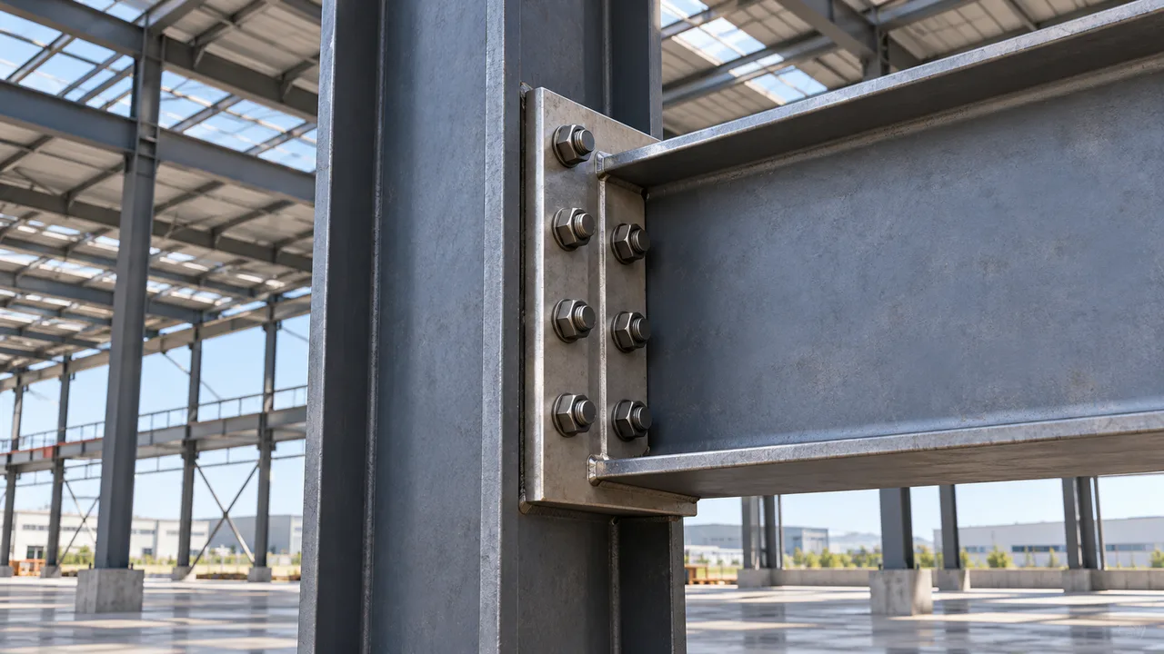
Continuity plates can provide a more direct path for concentrated beam flange forces to enter the column web and surrounding section. They can also reduce excessive deformation of the supporting flange when the flange alone does not provide adequate local resistance.
However, continuity plates should not be added automatically to every end-plate connection. Their need should be based on structural demand, flange resistance, web behavior, connection geometry, and the applicable design requirements.
The plate thickness, welds, fit-up, and alignment must also be sufficient to ensure that the intended reinforcement actually participates in the load path.
Common Design Mistakes
A common mistake is to select a thick end plate and assume that flange local bending is therefore no longer critical. This overlooks the fact that the end plate and supporting flange resist different local actions.
Another mistake is checking only bolt strength. Bolts may have sufficient tensile capacity while the end plate, supporting flange, welds, or adjacent web remain inadequate.
Ignoring prying action can also underestimate bolt demand when flexible plates are involved. Conversely, assuming that all flexible-plate behavior can be solved by simply increasing plate thickness may lead to unnecessary material use without addressing the actual governing condition.
Designers should also avoid adding reinforcement without confirming how the force enters and leaves the stiffened region. A stiffener that is poorly aligned with the beam flange force may not provide the intended structural benefit.
Fabrication and Detailing Considerations
Connection behavior depends on fabrication quality as well as calculation. End-plate flatness, bolt-hole alignment, weld continuity, plate fit-up, and contact conditions all influence the actual load path.
Welding can introduce distortion that changes the plate geometry before the connection is assembled. Misaligned holes may create installation forces or prevent uniform contact between the end plate and supporting flange.
Plate thickness also affects fabrication practicality. Very thick plates may require heavier welding, greater handling effort, and tighter control of distortion. The connection should therefore achieve the required structural stiffness without introducing unnecessary fabrication complexity.
Detailed provisions for steel connection design should follow the applicable project code and recognized standards such as those published by the American Institute of Steel Construction.
End-Plate Thickness in Industrial Steel Structures
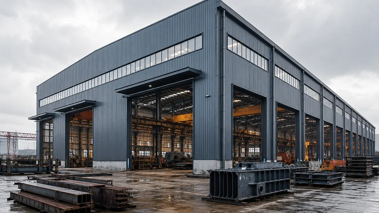
Industrial steel structures often contain connections subjected to larger and more concentrated forces than ordinary light framing. Crane-supporting frames, equipment platforms, transfer structures, large-span buildings, and heavy factory structures may all require moment connections with substantial flange forces.
In these applications, XTD Steel Structure coordinates member sizing, connection geometry, fabrication requirements, and local reinforcement so that the connection is evaluated as part of the complete structural system.
The objective is not simply to make the end plate thicker. The more important goal is to ensure that the beam flange force can pass through the plate, bolts, supporting flange, web, and surrounding structure without creating an unacceptable local limit state.
Practical Design Takeaway
The relationship between end-plate thickness and flange local bending is primarily a question of stiffness, deformation, and force distribution.
A thinner end plate generally permits greater plate bending and can increase sensitivity to prying action. A thicker plate reduces plate deformation and produces a stiffer connection, but it may also transfer concentrated force more directly into the supporting flange.
For this reason, reliable design requires the end plate, bolts, welds, supporting flange, web, and any continuity reinforcement to be checked together. Increasing one component alone does not guarantee that the complete connection will satisfy every relevant limit state.
FAQ About End-Plate Thickness and Flange Local Bending
Does a Thicker End Plate Reduce Flange Local Bending?
A thicker end plate can reduce plate deformation and change the distribution of forces entering the supporting flange, but it does not automatically eliminate flange local bending. The supporting flange must still have adequate thickness and local resistance for the applied bolt forces.
Can an End Plate Be Too Thin for a Moment Connection?
Yes. An end plate that is too thin may experience excessive bending, yielding, rotation, or prying action. These effects can increase bolt forces and reduce connection stiffness even when the plate has not experienced complete failure.
Does a Very Thick End Plate Eliminate the Need for Flange Checks?
No. A very thick end plate may behave almost rigidly relative to a thinner plate, but the supporting flange can still bend locally around the bolt rows. Flange local bending and related web limit states must be checked independently.
What Other Checks Are Required Around the End Plate?
Typical checks may include bolt tension, bolt shear where applicable, weld resistance, end-plate yielding, prying action, flange local bending, web local yielding, web instability, panel-zone behavior, and reinforcement requirements. The exact checks depend on the connection configuration and design code.
When Are Continuity Plates Needed?
Continuity plates may be required when the supporting flange or web cannot safely transfer the concentrated beam flange force without excessive local deformation or yielding. Their need should be established from the governing connection limit states rather than added automatically.