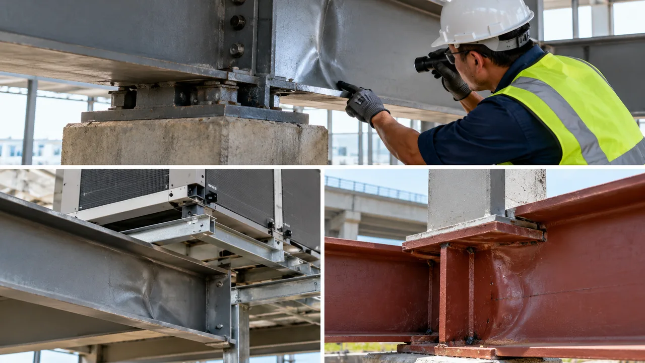
A steel beam or girder can remain generally straight across most of its span while serious deformation develops within a very small region near a support or concentrated load. The flange may rotate slightly, the web may bulge out of plane, or the steel directly beneath a bearing plate may appear crushed even though the member has not experienced an obvious global bending failure.
These local warning signs can indicate web crippling failure, a concentrated-force limit state that affects the web near the point where a compressive load enters the member. The problem is especially important in beams, girders, transfer members, light-gauge sections, and other steel components where substantial reactions must pass through a relatively thin web.
Because the damage is localized, it can be overlooked when attention is focused only on overall beam strength, deflection, or shear capacity. Effective prevention requires engineers to examine how concentrated forces enter the section, how much bearing length is available, whether the web has adequate local resistance, and whether stiffeners or other load-distribution measures are necessary.
What Happens During Web Crippling Failure?
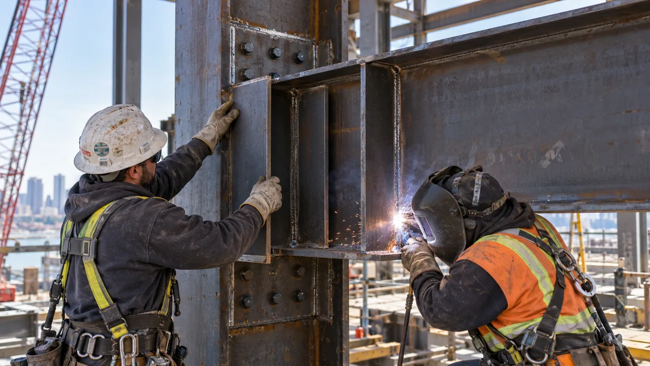
Web crippling develops when a concentrated compressive force produces severe localized deformation in the web of a steel member. Instead of the entire beam bending or the complete web panel buckling under shear, deformation is concentrated around the load introduction or reaction zone.
The web in this region is subjected to a combination of localized compression, bending, and instability. If the applied force becomes too large for the geometry and material properties of the web, the web can distort, buckle, fold, or develop permanent deformation adjacent to the loaded flange.
This behavior differs from a global member failure. A beam can have adequate flexural strength and still have insufficient resistance at a concentrated bearing location. The overall section may therefore appear capable of carrying the load while a relatively small web region becomes the controlling limit state.
Web crippling resistance is influenced by several geometric variables, including:
- Web thickness
- Overall member depth
- Flange thickness
- Effective bearing length
- Distance from the concentrated force to the member end
- Material yield strength
- Local restraint provided by the flange
- Presence and configuration of transverse stiffeners
Current structural steel design provisions treat web local crippling as one of the concentrated-force limit states that must be considered where applicable. The AISC Steel Construction Manual includes the current Specification for Structural Steel Buildings and related concentrated-force design requirements.
Where Web Crippling Commonly Occurs
The most vulnerable locations are usually places where a relatively large force must enter or leave the member through a short length of flange and web. Understanding these locations helps engineers identify critical regions before fabrication and helps inspectors know where to look after a structure has entered service.
At Beam And Girder Supports
Support reactions are one of the most common sources of concentrated compression. At the end of a beam, the total reaction may need to transfer through a relatively short bearing length into a column seat, bearing plate, wall, bracket, or another supporting member.
If the bearing area is small, the local force intensity increases. The end condition can also be more critical because less surrounding web material is available to distribute the reaction.
This is why support zones often require more than a simple check of global shear. The engineer must evaluate how the reaction passes from the flange into the web and whether the unstiffened web can safely resist that localized force.
Under Concentrated Loads
A concentrated load can create the same type of problem away from a support. Examples include reactions from secondary framing, heavy equipment, transfer beams, roof-mounted systems, or localized floor loads.
When a load is applied through a small bearing plate or narrow connection, the force does not immediately spread through the entire depth and length of the member. A highly stressed region develops first near the loaded flange.
If that force exceeds the local resistance of the web, deformation can occur even when the remainder of the member remains within its global strength limits.
Near Stiffeners And Connection Zones
A stiffener is intended to improve load transfer, but simply placing a plate beside the web does not automatically eliminate the problem. Its location, thickness, fit, connection, and contact with the relevant flange all affect performance.
A stiffener that stops short of the load path, has poor bearing contact, or is positioned away from the actual reaction may not transfer the force as intended. The web beside the stiffener can then continue to carry excessive localized compression.
Connection zones deserve similar attention. Seats, brackets, end connections, secondary beams, and transfer connections can introduce concentrated forces and local eccentricity that are not obvious from the overall framing layout.
In Thin-Web Built-Up Members
Deep built-up girders can use relatively slender webs to reduce steel weight. This is efficient for many global limit states, but it makes local concentrated-force behavior particularly important.
A deep web may have sufficient shear capacity while still requiring transverse stiffening at major reactions or concentrated loads. Plate girders used in industrial buildings, long-span structures, transfer systems, and heavy infrastructure therefore require coordinated checks of both global and local behavior.
Thin cold-formed or light-gauge members can also be sensitive because their webs have limited thickness and concentrated loads can create severe local deformation over a short distance.
Visible Signs Of Web Crippling Failure
The exact appearance of damage depends on the section geometry, loading, restraint, and severity of the problem. However, several field observations should trigger a closer structural review.
Local Web Buckling
One of the clearest signs is an out-of-plane bulge or buckle in the web immediately below or above a concentrated load.
The deformation may appear as a short wave, diagonal fold, or localized displacement rather than a buckle extending across the entire web panel. In severe cases, the original flat web surface can become visibly distorted around the bearing region.
Such deformation should not automatically be treated as cosmetic. Once the web geometry changes, the intended load path and local stiffness can also change.
Crushing And Permanent Web Distortion
The web may become indented or permanently folded near the loaded flange. This can occur when the local compressive demand becomes too high and the web can no longer maintain its original geometry.
Permanent deformation that remains after the load is removed is particularly important because it indicates that the member has experienced behavior beyond ordinary elastic movement.
The extent of visible distortion alone does not establish the remaining structural capacity. The surrounding flange, welds, stiffeners, and connections should also be examined.
Flange And Web Distortion Near The Bearing Point
Localized web deformation can affect the connected flange. The flange may rotate, bend locally, or lose uniform contact with the bearing plate or supporting surface.
This matters because the flange helps distribute concentrated force into the web. Once the bearing geometry becomes uneven, the reaction may become even more concentrated.
Inspectors should therefore look at the entire local region rather than only the center of the web.
Cracking Around Welds Or Stiffeners
Cracks around stiffener welds, connection welds, or adjacent base metal can indicate concentrated stress or unintended deformation.
A crack does not by itself prove that web crippling is the primary failure mode. It may result from welding defects, fatigue, local yielding, distortion, or another mechanism. However, cracking combined with visible web deformation near a high-reaction zone warrants detailed investigation.
The inspection should identify whether the crack is located at a weld toe, stiffener termination, flange-to-web region, or another stress concentration.
Increasing Deflection Or Misalignment
Local web damage can sometimes be accompanied by changes in alignment, bearing condition, or nearby member elevation.
These secondary symptoms should be interpreted carefully. Excessive global deflection may have a different cause, but unexpected movement close to a support can indicate that the local load-transfer region is no longer behaving as intended.
| Field Sign | Likely Structural Meaning | Area To Inspect |
|---|---|---|
| Web bulging | Possible local instability | Support or concentrated-load zone |
| Web indentation | High localized bearing demand | Directly below or above the applied force |
| Flange rotation | Disturbed local load path | Flange-web junction and bearing region |
| Cracking near welds | Possible stress concentration or secondary damage | Stiffeners, connections, and flange-web region |
| Permanent distortion | Possible yielding or local crippling | Web and adjacent flange |
Main Causes Of Web Crippling Failure
A web crippling failure normally develops because the concentrated force, member geometry, and local load-transfer details create a demand greater than the available web resistance. Several conditions can contribute simultaneously.
High Concentrated Reaction Forces
A large support reaction or point load places substantial compressive demand into a small region of the member.
This condition is common at transfer beams, heavily loaded girders, equipment supports, major roof reactions, industrial platforms, and locations where secondary framing delivers load to a primary beam.
The magnitude of the total reaction is important, but the manner in which the force is introduced is equally important. The same reaction distributed through a longer bearing length can create a different local demand from a reaction introduced through a very short plate.
Insufficient Bearing Length
A short bearing length concentrates the force into a smaller region of the flange and web.
Increasing effective bearing length can help distribute the reaction over a larger area, although the final design must still satisfy all applicable limit states. The bearing plate must also provide real contact. A nominally long plate offers little benefit if only a small part of it actually bears because of uneven fabrication or installation.
Bearing length should therefore be coordinated early with support geometry, connection detailing, and erection tolerances.
Thin Or Slender Webs
Reducing web thickness can improve material efficiency, especially in deep girders where a thick web may not be necessary for global strength.
However, thinner webs generally have less resistance to highly concentrated compression and local instability. The designer must therefore balance material efficiency against local limit states.
Optimizing a girder solely for weight can create additional requirements for stiffeners, doubler plates, connection detailing, or fabrication work. The lightest member is not necessarily the most economical completed solution.
Missing Or Inadequate Bearing Stiffeners
Transverse stiffeners can provide an additional load path where an unstiffened web does not have sufficient local resistance.
Problems arise when required stiffeners are omitted, undersized, poorly connected, misaligned with the applied load, or unable to transfer the force effectively to the adjacent flange.
Stiffener detailing should consider not only plate thickness but also fit, weld arrangement, end conditions, fabrication tolerance, and the actual direction of load transfer.
Poor Load Alignment
Concentrated forces should enter the member through the intended structural load path. Eccentric loading can introduce local bending in addition to compression.
This can occur when a bearing plate is offset, a secondary member frames into the primary beam away from the intended location, or installation tolerances shift the reaction from its design position.
Small geometric discrepancies can matter when the web is thin and the reaction is large. Connection and support details should therefore show clearly where the force is expected to act.
Connection Detailing Problems
Connections can unintentionally create severe local demand when force is introduced through a limited area or away from a suitable web location.
Seat connections, brackets, transfer connections, flange plates, and equipment supports should be evaluated as parts of the full load path. Local eccentricity, weld configuration, bearing contact, plate stiffness, and connection geometry may all influence the web response.
A connection that is adequate for bolts or welds is not automatically adequate for the connected beam web.
Fabrication And Installation Tolerances
The analytical model normally assumes a defined geometry, but the completed structure contains fabrication and erection tolerances.
A stiffener may have a gap, a web may contain initial distortion, a bearing plate may not sit evenly, or welding may pull the connection slightly out of alignment. Individually, these imperfections may appear minor. Under a large concentrated reaction, however, they can alter how the force enters the member.
Quality control should therefore verify critical bearing and stiffener details rather than focusing only on overall member dimensions.
Web Crippling vs Other Local Web Failures
Local web limit states can produce similar-looking damage, so terminology should not be based only on appearance. Web local yielding, web crippling, web buckling, shear-related instability, and flange deformation involve different mechanisms and may require different design checks.
| Failure Mode | Primary Mechanism | Typical Location | Common Visual Sign |
|---|---|---|---|
| Web crippling | Localized compression combined with instability and deformation | Support or concentrated-load region | Buckled, folded, or distorted web |
| Web local yielding | Localized compressive yielding of web material | Bearing or load introduction zone | Permanent local deformation |
| Web buckling | Instability of a slender web region | Compressed web panel or locally restrained region | Out-of-plane buckle |
| Web shear failure | Excessive shear demand or shear instability | Web panel between supports or stiffeners | Diagonal distortion or buckling pattern |
| Flange local bending | Localized bending of the flange | Concentrated-force connection | Visible flange deformation |
These mechanisms can also interact. A concentrated load may produce local web yielding before significant instability develops, while flange deformation or poor bearing contact may change the distribution of load into the web. For that reason, an observed deformation should be evaluated using the actual section, load position, support condition, connection geometry, and applicable design provisions rather than being classified from photographs alone.
How Engineers Evaluate Web Crippling Risk
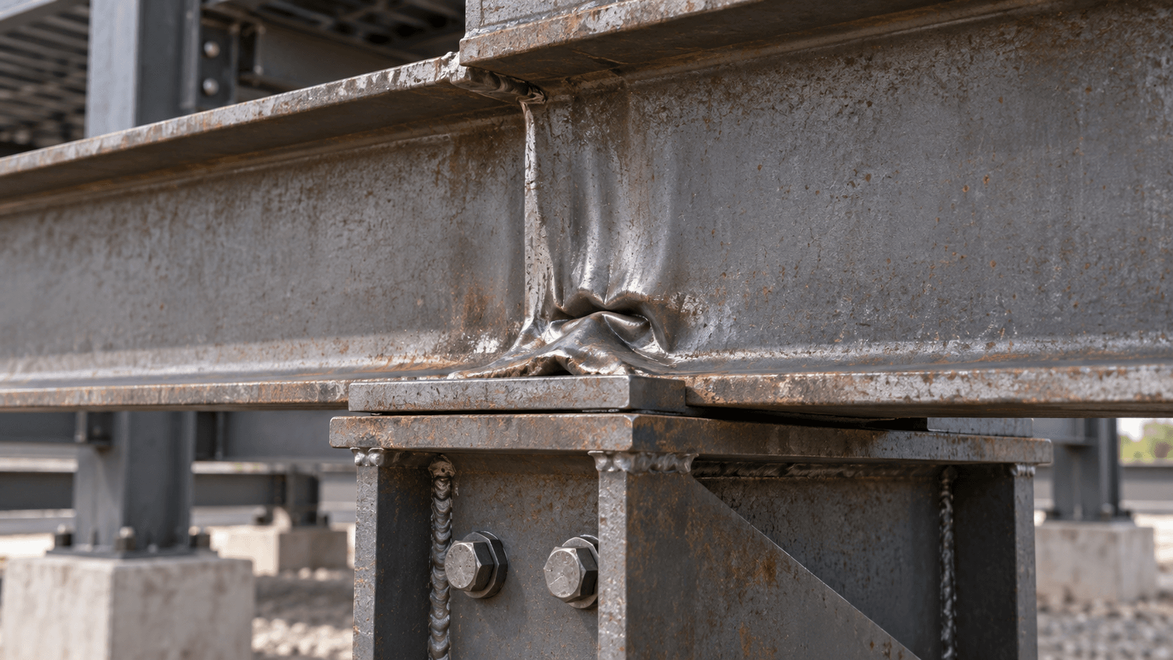
Visual inspection can identify possible damage, but evaluating web crippling failure risk requires a calculation-based review of the member and its concentrated forces.
Determine The Applied Concentrated Force
The engineer first identifies the reaction or point load entering the member and the governing load combinations. Possible sources include support reactions, equipment loads, reactions from secondary beams, transfer forces, roof systems, platforms, and other concentrated actions. The design force must correspond to the relevant structural design method and applicable code requirements. Using an underestimated reaction can make every subsequent local check unconservative.
Identify The Effective Bearing Length
The length over which the force bears on the flange influences how concentrated the load becomes. The engineer should distinguish between the physical size of a bearing component and the portion that actually transfers load. Plate geometry, contact condition, support arrangement, and location relative to the member end all matter. A longer effective bearing region can distribute force more favorably, but bearing length should never be assumed without confirming the actual detailing.
Check The Web Geometry
Important member properties include web thickness, member depth, flange thickness, material strength, and relevant flange-to-web geometry. Distance from the concentrated force to the member end also matters because end reactions do not have the same surrounding web region available for load distribution as interior concentrated forces. These dimensions should come from the actual section being designed or inspected rather than from a generic member category.
Evaluate Stiffener Conditions
If transverse stiffeners are present, the engineer should confirm their dimensions, position, connection, and ability to participate in the intended load path. For an existing structure, the review should also check whether the installed stiffeners match the drawings and whether gaps, corrosion, distortion, damaged welds, or later modifications affect their performance. A stiffener should not simply be assumed effective because a plate is visible beside the web.
Consider End And Interior Loading
The location of a concentrated compressive force relative to the member end affects local behavior and available resistance. An interior load has web material extending on both sides of the loaded region, while an end reaction has less surrounding material available to participate in load distribution. Design provisions therefore distinguish between loading conditions according to the force location and member geometry. For a calculation-focused explanation of the required parameters and design sequence, see our web crippling design checks.