Structural steel connections rarely carry only one type of force. Beam connections, bracing systems, portal frames, trusses, and industrial structures may experience axial force, shear, bending moment, eccentric loading, or several of these actions simultaneously. Understanding weld and bolt capacity under loads therefore requires more than checking the nominal strength of an individual weld or bolt.
The actual resistance of a connection depends on how forces enter the joint, how they are distributed through weld groups or bolt groups, and how the connected plates and structural members respond. A connection may have strong bolts but still be controlled by plate bearing, net-section fracture, or block shear. Similarly, a large weld may have sufficient theoretical resistance while the adjacent base metal becomes the governing limit state. Reliable connection design must evaluate the entire load path and all relevant failure modes.
Understanding Weld and Bolt Capacity Under Loads
Why Load Type Changes Connection Behavior
The direction and position of a load strongly influence connection behavior. A connection subjected to direct shear distributes force differently from one subjected to axial tension or bending moment. When loads act eccentrically, additional moments may develop even when the externally applied force appears relatively simple.
Connection geometry also affects how forces are distributed. The spacing of bolts, length and orientation of welds, plate dimensions, connection depth, stiffness, and distance from the load line to the connection centroid can all change the demand on individual components.
Individual Fastener Capacity vs Complete Connection Capacity
The nominal strength of a bolt or weld is only one part of the complete connection. Structural bolts may have adequate shear or tension resistance while the connected plate fails in bearing, tear-out, net-section fracture, or block shear. Welds may have sufficient resistance while the connected base metal yields, fractures, or locally deforms.
For this reason, engineers evaluate the fasteners, welds, plates, structural members, and connection geometry together rather than treating the nominal fastener capacity as the final connection capacity.
Importance of the Complete Load Path
Structural forces must move continuously from one member through the connection and into the supporting member. The load path may include beams, columns, gusset plates, end plates, stiffeners, bolts, welds, and other structural components. Understanding axial shear moment and lateral loads helps engineers identify how these forces interact as they pass through the connection.
If one component along this path has significantly lower resistance than the others, it may determine the actual connection capacity.
Weld and Bolt Capacity Under Axial Loads
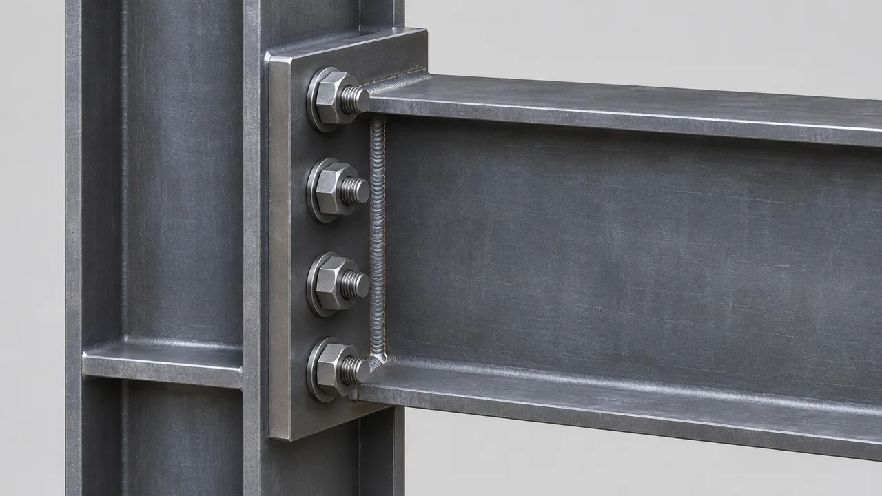
Axial Tension in Welded Connections
When a welded connection transfers axial tension, the force must pass through the weld into the connected steel. Fillet weld resistance depends on the effective throat, weld length, filler metal strength, weld orientation, and geometry of the weld group. Groove welds may provide more direct force transfer and can develop high resistance when properly designed and executed.
However, increasing weld strength alone does not guarantee greater connection capacity. The connected plate or base metal may yield or rupture before the weld reaches its maximum resistance.
Axial Tension in Bolted Connections
Bolted connections subjected to axial tension require the bolts to resist tensile force. The distribution of tension among multiple bolts depends on connection stiffness and geometry. Flexible plates can also develop prying action, which introduces additional bolt tension beyond the externally applied force.
The connected plate must also be checked for net-section fracture around bolt holes, block shear, local yielding, and other applicable limit states.
Axial Compression in Connections
Compression may be transferred directly through contact between connected surfaces, through welds, or through bearing depending on the connection arrangement. Bolts may primarily maintain alignment and stability while compressive force passes through contact surfaces.
Under high compression, local plate deformation, buckling, bearing, and member instability may become more important than the nominal strength of the weld or bolt itself.
Key Failure Modes Under Axial Loads\
Common limit states under axial loading include bolt tension fracture, weld rupture, base metal yielding, net-section fracture, block shear, plate deformation, and local buckling. The governing condition depends on the connection arrangement and whether the load acts in tension or compression.
Weld and Bolt Capacity Under Shear Loads
Shear Transfer Through Welds
Welded connections frequently transfer shear through fillet welds. The effective throat area, weld length, filler metal strength, and loading direction determine the available resistance. Longitudinal and transverse welds may respond differently because the direction of loading relative to the weld axis affects stress distribution.
A weld group must also be evaluated as a complete system when several weld segments share the applied shear.
Shear Transfer Through Bolts
In a conventional bearing-type connection, bolts transfer shear while the bolt shank bears against the connected plate. Bolt shear resistance depends on bolt diameter, bolt grade, number of shear planes, and whether the threaded portion passes through the shear plane.
A bolt in double shear can engage two shear planes, while a bolt in single shear has one primary shear plane. The configuration therefore directly affects available resistance.
Plate Bearing and Tear-Out
Bolt capacity cannot be separated from the behavior of the connected plate. As the bolt presses against the side of the hole, local bearing stresses develop. Plate thickness, material strength, edge distance, bolt spacing, and hole geometry influence the available bearing resistance.
If a bolt is placed too close to the plate edge, the material between the hole and the edge can tear out before the bolt itself fails.
How Shear Distribution Changes in Bolt and Weld Groups
For simple symmetrical connections, engineers may begin with an idealized equal distribution of direct shear among bolts or weld segments. Real connections, however, may develop unequal forces due to stiffness differences, eccentric loading, geometry, and deformation.
The most heavily loaded bolt or weld segment may therefore govern the connection even when the average demand appears acceptable.
Weld and Bolt Capacity Under Moment Loads
How Moment Creates Tension and Compression Forces
A bending moment is typically resisted by a force couple consisting of tension on one side of the connection and compression on the opposite side. The distance between these forces creates the lever arm needed to resist the applied moment.
Increasing the effective connection depth can reduce the magnitude of the required tension and compression forces for the same applied moment, which is why connection geometry plays such an important role.
Weld Groups Under Moment
When a weld group resists moment, stresses are not distributed uniformly. Weld segments located farther from the centroid of the group may experience greater demand. If the connection also carries direct shear or axial force, these stresses must be combined.
Eccentric welded connections therefore require evaluation of both the direct force and the additional moment created by the offset load.
Bolt Groups Under Moment
Moment can create different tensile forces in individual bolts. Bolts farther from the center of rotation generally experience greater tensile demand, while compression may be transferred through contact between plates or connected members.
The bolt group should therefore be analyzed based on its geometry rather than simply dividing the applied moment equally among all bolts.
Prying Action in Bolted Moment Connections
Flexible end plates and flanges can deform under tension and create prying forces that increase bolt tension. This additional force can be significant even when the externally applied tensile load appears acceptable.
For this reason, checking only the direct bolt tension may underestimate the actual demand in some moment connections.
Failure Modes Under Moment Loading
Possible limit states include bolt tension fracture, weld rupture, end-plate yielding, flange local bending, base metal failure, stiffener yielding, and excessive connection deformation. The governing mode depends on the relative strength and stiffness of each component.
Combined Axial, Shear, and Moment Loads
Why Combined Loading Is Common
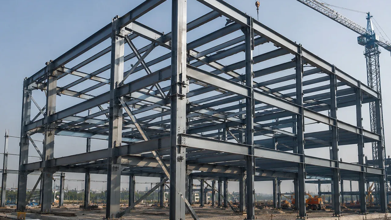
Many structural connections carry several load components simultaneously. Beam-to-column connections may resist shear and moment. Bracing connections may transfer axial force together with secondary shear. Portal frame joints can experience axial force, shear, and large bending moments at the same time.
Industrial steel buildings may also introduce crane loads, equipment forces, vibration, and lateral actions that create complex combinations of demand.
Combined Tension and Shear in Bolts
When a bolt carries tension and shear simultaneously, the two demands cannot always be checked independently. Interaction between them reduces the amount of resistance available for each action.
A bolt that is acceptable under pure shear and acceptable under pure tension may still become inadequate when both demands act together.
Combined Stress in Weld Groups
Weld groups may experience direct shear, axial force, torsion, and bending moment simultaneously. These actions create different stress components along the weld group.
Engineers must determine the critical resultant demand rather than checking each force component in isolation.
Why Separate Capacity Checks Are Not Enough
Evaluating weld and bolt capacity under loads requires consideration of load interaction. A connection may satisfy separate axial and shear checks while becoming overstressed when these demands occur simultaneously with moment or eccentricity.
Combined-load evaluation therefore provides a more realistic representation of how the connection performs in the actual structure.
Effect of Eccentric Loading on Weld and Bolt Capacity
What Is Connection Eccentricity?
Connection eccentricity occurs when the applied force does not pass through the centroid or effective resistance center of the connection. The offset distance creates an additional moment equal to the applied force multiplied by the eccentricity.
Even a relatively modest direct force can therefore create significant additional demand when the eccentricity is large.
Eccentric Weld Groups
In an eccentric weld group, direct force acts together with the secondary moment created by the offset load. This produces unequal stresses along the weld group, with certain weld segments carrying greater demand.
Ignoring this secondary moment can significantly underestimate the required weld capacity.
Eccentric Bolt Groups
Eccentric bolt groups also experience unequal force distribution. Bolts positioned farther from the group centroid may develop higher forces, and some configurations can produce combined shear and tension in individual bolts.
Bolt arrangement and spacing therefore influence both structural capacity and load distribution.
Factors That Control Weld Capacity Under Different Loads
Weld Type
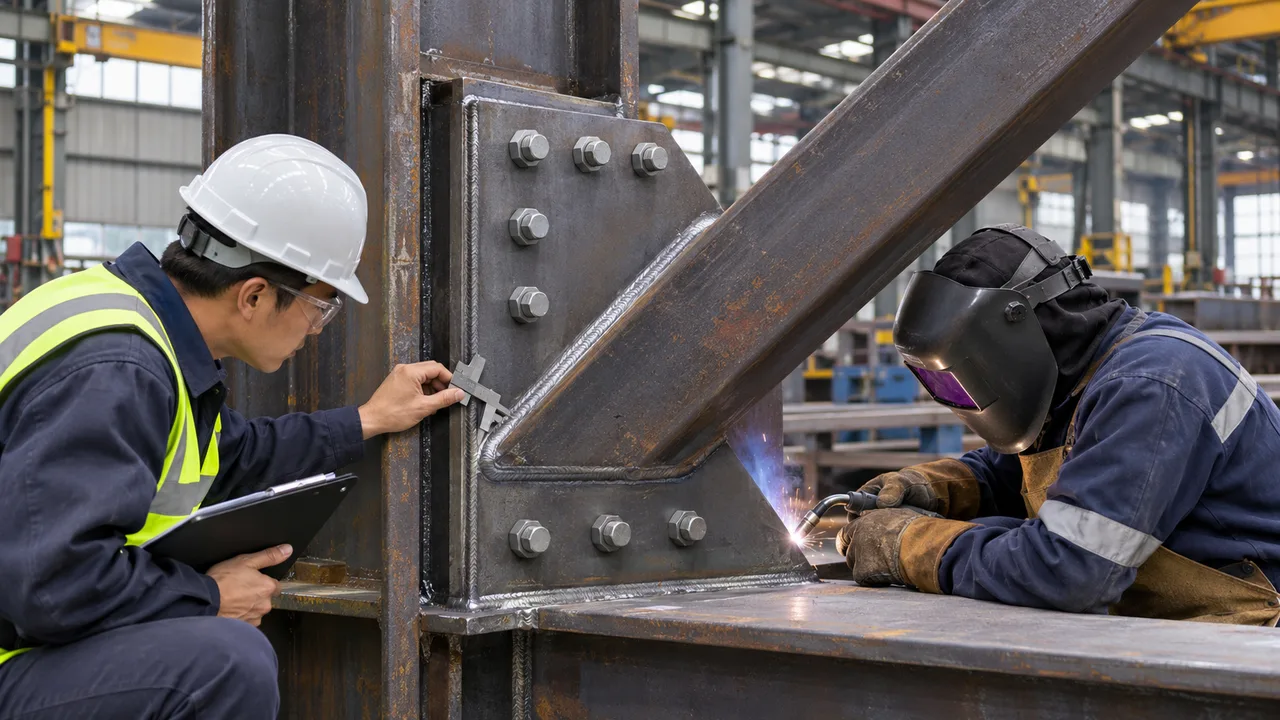
Fillet welds, partial-joint-penetration groove welds, and complete-joint-penetration groove welds provide different resistance and force-transfer characteristics. Selection depends on load demand, joint geometry, fabrication access, and structural requiremenMany steel structures combine welding and bolting rather than relying entirely on one method. An end plate can be welded to a beam in the fabrication shop and then bolted to a column during erection. Similarly, a gusset plate may be welded to a supporting member while the brace is bolted to the gusset on site.
These arrangements allow controlled shop welding while maintaining the speed and flexibility of field bolting. Hybrid connection systems can therefore provide an effective balance between structural performance, fabrication quality, transportation efficiency, and erection speed.
Fabrication and Installation Effects on Connection Capacity
Welding Quality Control
Welded connection performance depends on qualified personnel, appropriate welding procedures, correct fit-up, controlled heat input, suitable sequencing, and proper inspection. Fabrication defects can reduce the actual resistance below the intended design capacity.
Bolt Installation Control
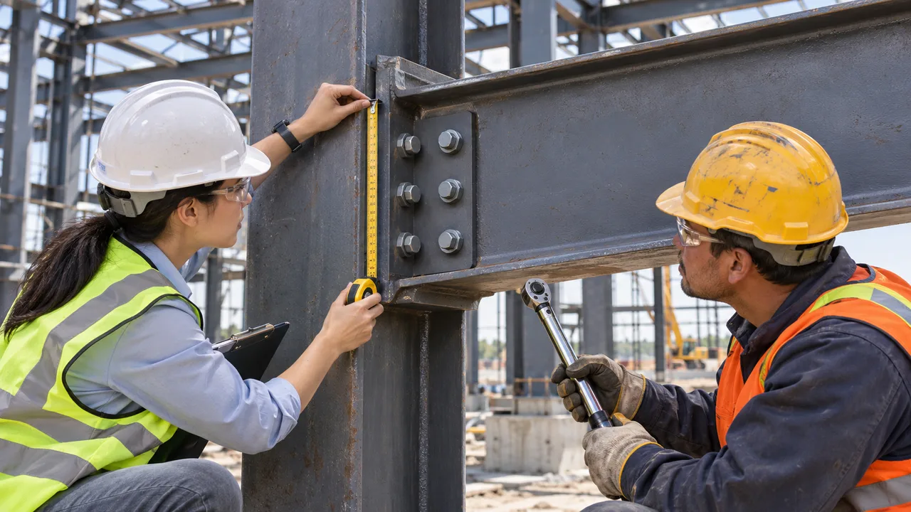
Bolted connections require the correct bolt grade, accurate hole alignment, suitable washers, proper tightening procedures, and correct pretension where specified.
Fabrication Tolerance
Poor fit-up or inaccurate hole positioning can introduce unintended eccentricity and redistribute forces within the connection. Fabrication tolerances therefore influence actual structural behavior as well as erection efficiency.
When Welded Connections May Be Better Under Loads
Controlled Factory Fabrication
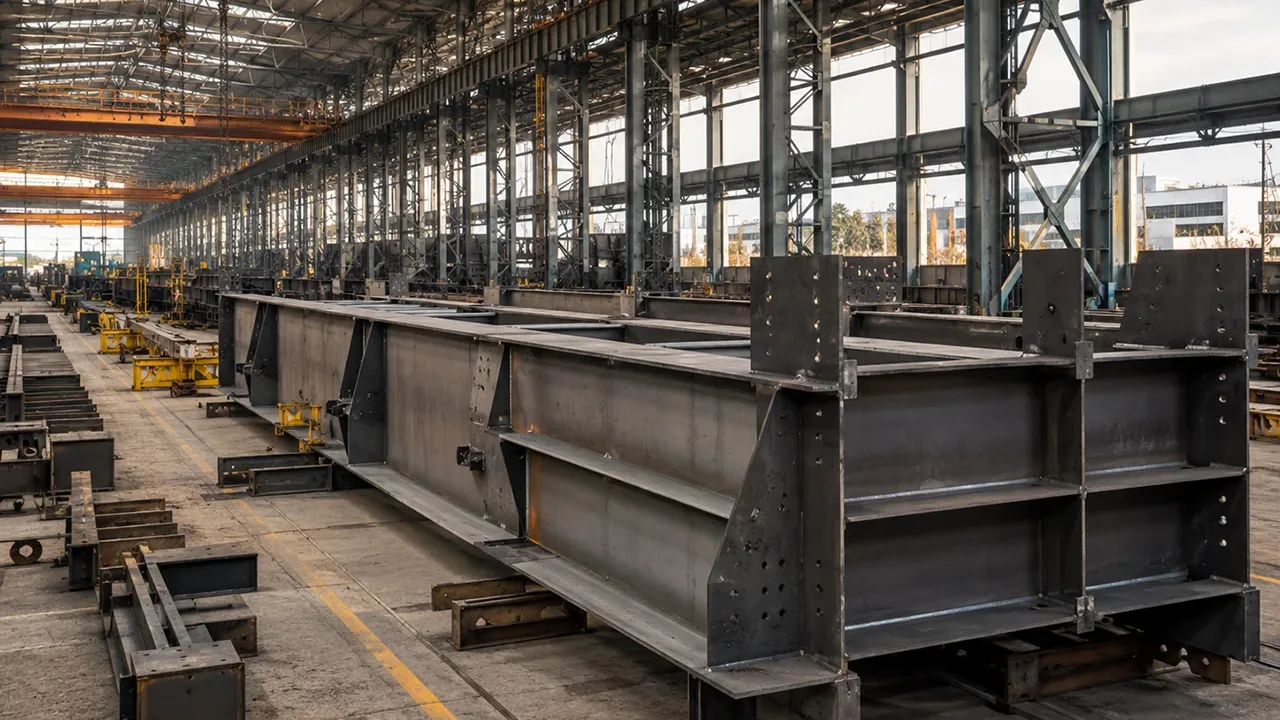
Welded connections can perform efficiently when fabrication occurs under controlled conditions. A well-managed Steel structure factory can control fit-up, welding procedures, heat input, positioning, distortion, and inspection more consistently than many construction sites. XTD Steel Structure integrates connection detailing with controlled fabrication so welded components can be prepared before transportation and erection.
Compact Connection Geometry
Welding can reduce the space required for bolt heads, nuts, and installation tools, making it useful in compact or congested connections.
Continuous Force Transfer Requirements
Built-up members, stiffeners, moment connection components, and fabricated assemblies can benefit from continuous force transfer along welded interfaces.
High-Stiffness Fabricated Assemblies
Welded assemblies can provide relatively stiff and compact connections where deformation control is important.
When Bolted Connections May Be Better Under Loads
Fast Site Erection
Bolted connections allow prefabricated members to arrive on site ready for assembly, reducing the amount of field welding and accelerating erection.
Connections Requiring Adjustment
Bolt holes and erection tolerances can provide greater adjustment during assembly than fully welded connections.
Remote or Difficult Site Conditions
Wind, rain, restricted access, limited electrical power, and shortages of qualified welding personnel may make field bolting more practical.
Future Disassembly or Modification
Bolted connections can be advantageous in modular structures, equipment supports, and facilities that may later require expansion or modification.
How Engineers Evaluate Weld and Bolt Capacity Under Loads
Evaluating weld and bolt capacity under loads typically involves the following sequence:
-
- Determine the axial force acting on the connection.
- Determine the applied shear force.
- Determine the bending moment.
- Identify any connection eccentricity.
- Define the complete load path.
- Calculate the demand on welds or bolts.
- Evaluate interaction between combined loads.
- Check connected plate capacity.
- Check the surrounding base metal and structural members.
- Evaluate bearing, tear-out, net-section fracture, and block shear where applicable.
- Review fabrication and installation conditions.
- Identify the governing limit state and confirm adequate connection resistance.
This process prevents designers from relying on a single nominal capacity value and helps ensure that the connection performs as a complete structural system.
Common Design Mistakes
- Checking axial, shear, and moment loads independently without considering interaction
- Comparing only individual bolt strength with weld strength
- Ignoring connection eccentricity
- Ignoring prying action in tension connections
- Assuming equal bolt load distribution in every configuration
- Ignoring plate bearing and tear-out
- Ignoring net-section reduction caused by bolt holes
- Oversizing welds without checking the base metal
- Ignoring weld-group geometry
- Ignoring fabrication tolerances
- Ignoring site installation conditions
- Assuming that the strongest individual fastener automatically produces the strongest connection
Frequently Asked Questions
Does Weld Capacity Change with Load Direction?
Yes. Weld performance depends on the direction of loading relative to the weld axis, the geometry of the weld group, and whether the connection is subjected to shear, tension, moment, torsion, or combined actions.
Does Bolt Capacity Change Under Combined Shear and Tension?
Yes. When bolts are subjected to tension and shear simultaneously, interaction between these forces must be considered. A bolt that is adequate under each load separately may not remain adequate under their combined effect.
How Does Moment Affect a Bolt Group?
Moment creates unequal forces within the bolt group. Bolts positioned farther from the center of rotation typically experience greater tensile demand, depending on the connection geometry and stiffness.
How Does Moment Affect a Weld Group?
Moment produces nonuniform stress throughout a weld group. Weld segments farther from the centroid may experience higher demand, especially when the connection also carries direct shear or axial force.
Can Welds and Bolts Carry Axial, Shear, and Moment Loads at the Same Time?
Yes. Structural connections frequently carry several load components simultaneously. The connection must be checked for combined effects rather than treating each force independently.
What Usually Controls Connection Capacity Under Combined Loads?
The governing limit state may be bolt shear, bolt tension, weld rupture, plate bearing, tear-out, net-section fracture, block shear, base metal yielding, local bending, buckling, or another connected component. The lowest applicable resistance generally controls the final connection capacity.
Conclusion
Weld and bolt capacity under loads cannot be determined from a single nominal strength value. Axial force, shear, moment, eccentricity, and combined loading change how forces are distributed through welds, bolts, plates, and connected structural members.
Welded connections can provide compact geometry and continuous force transfer, while bolted connections can improve erection speed, adjustability, inspection, and site practicality. In many structures, combining shop welding with field bolting provides an efficient balance between structural performance and construction requirements.
The final connection should therefore be designed by evaluating the complete load path, interaction between loads, weld or bolt resistance, connected plate behavior, base metal capacity, fabrication quality, installation conditions, and the governing failure mode as one integrated structural system.