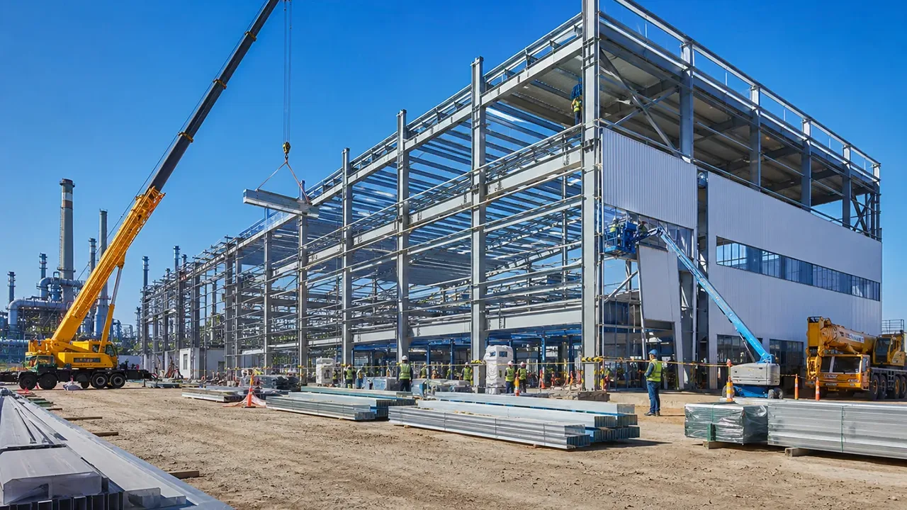
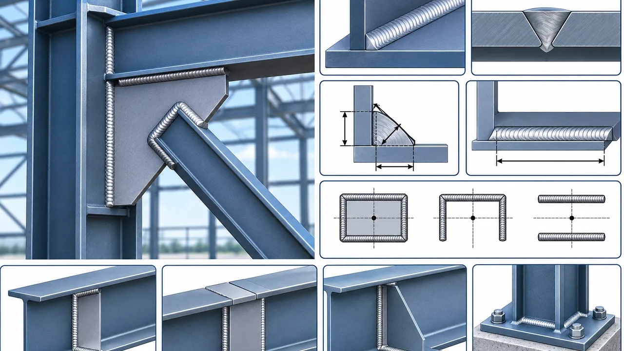
Welded connections are essential in structural steel construction because they transfer forces between plates, beams, columns, braces, stiffeners, and other fabricated components. A connection may appear simple on a drawing, but its performance depends on whether the weld, surrounding base metal, and connected members can safely resist the actual load path.
weld capacity design is the process of determining whether a welded connection provides sufficient resistance for the forces acting through it. The calculation involves more than selecting a weld size. Engineers must consider the weld type, effective throat, effective length, electrode strength, base metal strength, force direction, weld-group geometry, eccentricity, and potential failure modes.
These considerations are important in plate connections, beam assemblies, gusset plates, bracing systems, moment connections, stiffeners, brackets, and other structural details. Reliable welded connections require the weld and the connected steel to work together as one continuous load-transfer system.
What Is Weld Capacity Design?
weld capacity design evaluates the resistance available from a weld and compares it with the forces the connection must transfer. The objective is to ensure that the weld has sufficient capacity while also confirming that adjacent plates, beams, braces, and other components do not fail first.
A connection can contain a weld that is stronger than necessary while the surrounding steel remains inadequate. For example, a large weld may successfully transfer force into a thin plate, but the plate itself may yield, tear, buckle, or experience local deformation. For this reason, weld resistance should never be evaluated in isolation.
Main Variables Affecting Weld Capacity
Important variables include:
- Weld type
- Nominal weld size
- Effective throat thickness
- Effective weld length
- Weld metal strength
- Base metal strength
- Direction of loading
- Weld orientation
- Connection eccentricity
- Fabrication and inspection quality
Weld Capacity vs Connection Capacity
Weld capacity refers specifically to the resistance provided by the welded portion of the connection. Connection capacity includes every component involved in transferring the force.
A complete check may therefore include weld metal fracture, plate yielding, plate rupture, beam web shear, flange yielding, gusset plate deformation, local buckling, and other limit states. The governing connection capacity is controlled by the weakest relevant component rather than by the weld alone.
Common Weld Types in Structural Steel Connections
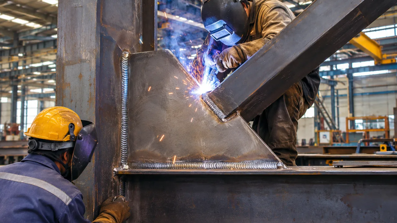
Fillet Welds
Fillet welds are among the most widely used welds in structural steel fabrication. They are commonly applied where two steel surfaces meet at approximately a right angle or where one plate overlaps another.
Typical applications include gusset plates, beam web connections, stiffeners, brackets, base details, and bracing connections. The strength of a fillet weld is influenced by its leg size, effective throat, effective length, weld metal strength, and loading direction.
Groove Welds
Groove welds are used when steel components are joined along prepared edges. They may provide partial or complete penetration through the thickness of the connected material.
A complete-joint-penetration weld can transfer significant forces when properly designed and executed. Partial-joint-penetration welds have a smaller effective throat and must be evaluated according to the actual penetration provided.
Plug and Slot Welds
Plug and slot welds may be used in overlapping plate connections where additional force transfer is required through openings in one component. Their geometry and application differ from ordinary fillet welds, and they should be designed according to the actual connection configuration.
Choosing the Appropriate Weld Type
Weld selection depends on structural demand, plate thickness, connection geometry, fabrication access, welding position, required inspection, and whether the connection will be produced in the shop or at the project site.
An efficient connection uses a weld type that provides the required resistance without creating unnecessary fabrication complexity.
How Weld Forces Are Transferred
Direct Shear
Direct shear occurs when a force acts generally parallel to the connected interface. This condition is common in beam web connections, lap joints, connection plates, and some brace details.
The force is distributed through the effective weld group. The designer must determine whether the available weld area can resist the required shear demand.
Tension and Normal Forces
Some connections transfer force across the weld rather than parallel to it. Direct tension can occur in flange connections, groove welds, brackets, and other joints where force acts normal to the connected surface.
The response depends on the weld type, joint preparation, force direction, and behavior of the surrounding base metal.
Combined Loading
Structural welds frequently resist more than one type of force. A weld group may experience shear, tension, and moment effects simultaneously.
Checking only one force component can therefore underestimate the actual demand. Combined loading should be evaluated using the applicable design method so that the interaction between forces is properly considered.
Eccentric Loading
When an applied force does not pass through the centroid of a weld group, the eccentricity creates an additional moment. The welds must then resist both the direct force and the moment-induced demand.
This condition is common in brackets, offset connection plates, and bracing connections where the brace force does not align perfectly with the weld-group centroid.
Key Parameters in Weld Capacity Design
Weld Size
For a fillet weld, weld size generally refers to the leg dimension. Increasing the weld size usually increases the available resistance because the effective throat becomes larger.
However, increasing weld size is not always beneficial. Very large welds can require greater heat input, increase distortion, consume more filler metal, and provide little benefit when the connected base metal already governs the connection.
Effective Throat Thickness
The effective throat is the critical weld dimension through which force is transferred. In a fillet weld, it is smaller than the nominal leg size.
This distinction is important because the resisting weld area is based on the effective throat rather than simply on the visible weld dimensions.
Effective Weld Length
The effective weld length represents the portion of the weld that can be considered active in transferring force. Weld termination, end conditions, detailing, and applicable structural requirements influence the effective length.
Increasing weld length can increase resistance, but very long welds may not always distribute force uniformly due to differences in stiffness and deformation along the connection.
Weld Metal Strength
The strength of welding consumables affects the nominal resistance of the weld. Electrode selection should be compatible with the base material, welding process, loading requirements, and project specifications.
Base Metal Strength
The connected plate or structural member must be capable of receiving the force transmitted by the weld. Base metal yielding, rupture, shear failure, or local tearing can govern even when the weld itself has greater nominal strength.
Fillet Weld Capacity
Effective Weld Area
The resisting area of a fillet weld is determined from the effective throat multiplied by the effective weld length. This effective area forms the basis for evaluating the available weld resistance.
For practical design, engineers often evaluate the resistance provided per unit length of weld and then determine how much effective weld length is required to transfer the applied load.
Weld Strength per Unit Length
Weld resistance per unit length increases as the effective throat or weld metal strength increases. This provides a practical way to compare different weld sizes and estimate the required weld length for a connection.
Single vs Multiple Weld Lines
A connection may use a single weld line, two parallel welds, welds on both sides of a plate, transverse welds, or a combination of several weld segments.
Balanced weld arrangements are generally preferred because they can reduce eccentricity and distribute forces more evenly across the connected components.
Long Weld Considerations
Long welds can provide substantial nominal resistance, but they may not transfer force uniformly along their entire length. Differences in stiffness and deformation can concentrate demand near particular areas of the connection.
Applicable structural design requirements should therefore be considered when very long welds are used.
Groove Weld Capacity
Complete-Joint-Penetration Welds
Complete-joint-penetration welds extend through the full thickness of the joint. When properly detailed, fabricated, and inspected, they can provide a direct force-transfer path capable of developing substantial resistance.
They are commonly used in highly loaded connections, moment-resisting joints, flange splices, and locations where full force transfer is required.
Partial-Joint-Penetration Welds
Partial-joint-penetration welds do not extend through the full connected thickness. Their capacity is based on the effective throat provided by the joint preparation and actual weld penetration.
Careful detailing is required to ensure adequate access, preparation, and quality during fabrication.
When Groove Welds Are Preferred
Groove welds may be appropriate for thick plates, direct tension connections, moment connections, highly loaded joints, or locations where available space does not permit an efficient fillet weld arrangement.
Weld Capacity Design for Steel Plates
Plate-to-Plate Connections
Steel plates may be connected using lap joints, T-joints, butt joints, or other arrangements. The selected connection must account for plate thickness, weld orientation, force direction, available edge distance, and local plate response.
The weld should transfer force without causing premature yielding, rupture, tearing, or excessive distortion in the connected plates.
Stiffener Plate Connections
Stiffeners are commonly welded to beam webs, column webs, flanges, and other structural components. The weld must transfer the required force between the stiffener and supporting member while the stiffener itself remains stable.
Bearing stiffeners and highly loaded web stiffeners can introduce concentrated forces that require careful evaluation of both weld resistance and local base metal behavior.
Connection Plates and Brackets
Connection plates and brackets may experience combined shear, bending, and eccentric loading. The weld group should therefore be evaluated together with plate bending and local yielding.
Weld Capacity Design for Beams
Beam Web Connections
Beam webs commonly transfer shear through welded connection plates, shear tabs, stiffeners, or framing connections. The weld must provide enough resistance to transfer the required shear while the beam web and connection plate also remain adequate.
Beam Flange Connections
Beam flanges may transfer significant tension or compression, particularly in moment-resisting connections. These concentrated forces can require continuous or highly effective weld arrangements.
weld capacity design for beam flanges should consider not only weld resistance but also flange strength, supporting column behavior, local stresses, and connection geometry.
Beam-to-Column Connections
Beam-to-column connections can range from simple shear connections to rigid moment-resisting joints. Weld requirements must correspond to the intended structural behavior.
A connection intended primarily for shear may require only web force transfer, while a moment connection may require substantial flange and web weld capacity.
Weld Capacity Design for Bracing Connections
Brace-to-Gusset Plate Welds
Diagonal braces primarily transfer axial tension or compression. When a brace is welded to a gusset plate, the weld arrangement must transfer this axial force without producing unnecessary eccentricity.
Welds may be positioned along one or both sides of the brace depending on the brace section and connection configuration. Balanced weld layouts can improve load distribution and reduce secondary bending.
Gusset Plate-to-Frame Welds
The gusset plate must also transfer brace forces into the beam, column, or beam-column joint. The weld between the gusset plate and supporting frame should therefore be evaluated based on the actual force path.
Increasing the weld size alone does not guarantee adequate performance if the beam web, column flange, gusset plate, or other connected component cannot resist the transferred force.
Force Alignment and Work Point
Bracing connections perform more efficiently when the brace centerline aligns closely with the intended structural work point. When alignment is poor, eccentricity can introduce additional moments into the gusset plate and weld group.
Proper coordination of the brace, gusset plate, beam, and column is therefore important when detailing a gusset plate braced connection. The complete load path should be evaluated rather than considering the brace weld separately.
Compression Brace Considerations
Compression braces may buckle and rotate during severe loading. The gusset plate and surrounding welds must continue transferring forces while accommodating the expected connection behavior.
Overly restrictive detailing can interfere with required deformation, particularly in systems where ductile behavior is expected.
Weld Group Design and Load Distribution
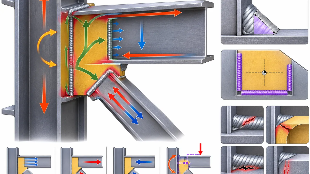
Weld Group Centroid
The weld-group centroid is the geometric center of the effective weld arrangement. Its location becomes particularly important when the applied force is eccentric.
Direct Force Distribution
For a concentrically loaded weld group, the direct force is distributed through the effective weld area. The actual demand depends on the weld pattern, loading direction, and stiffness of the connected parts.
Moment-Induced Forces
An eccentric load generates a moment about the weld-group centroid. Weld segments farther from the centroid may experience greater secondary demand.
The direct and moment-induced forces should be combined to determine the resultant demand acting on critical portions of the weld group.
Weld Pattern Geometry
Common weld patterns include parallel weld lines, rectangular groups, U-shaped configurations, perimeter welds, and asymmetric arrangements. Geometry influences both the distribution of force and the resistance of the connection to eccentric loading.
Base Metal Checks Around Welded Connections
Base Metal Yielding
The plate or structural member adjacent to the weld must have enough cross-sectional area to resist the transmitted force. If the surrounding steel yields before the weld reaches its capacity, base metal yielding governs the connection.
Base Metal Rupture
Local fracture may occur when the available section around the weld is insufficient. A high-strength weld cannot compensate for inadequate base metal dimensions.
Local Shear Failure
Highly loaded welded connections can introduce concentrated shear into beam webs, plates, gussets, or other components. Local tearing or shear yielding should therefore be checked where appropriate.
Lamellar Tearing
Lamellar tearing can occur when thick steel plates are subjected to significant through-thickness tensile stress, particularly in highly restrained welded joints.
Material selection, joint geometry, welding sequence, and detailing can help reduce this risk.
Common Weld Failure Modes
Weld Throat Failure
An insufficient effective throat may not provide enough area to resist the applied force. Excessive shear or combined stress can then cause failure through the weld throat.
Weld Metal Fracture
Weld metal fracture may result from excessive structural demand, unsuitable consumables, welding defects, inadequate fusion, or other quality problems.
Base Metal Failure
In some connections, the plate or structural member yields or fractures before the weld. The weld and connected steel must therefore be designed together rather than independently.
Cracking
Hydrogen cracking, hot cracking, and crater cracking may occur under unfavorable combinations of material properties, restraint, heat input, welding procedure, and environmental conditions.
Lack of Fusion or Penetration
Incomplete fusion or insufficient penetration reduces the effective weld area and can significantly reduce connection reliability. Proper joint preparation and welding technique are essential.
Undercut and Porosity
Undercut and excessive porosity may reduce the effective cross section and create stress concentrations. Inspection and acceptance criteria are therefore important components of quality control.
Shop Welding vs Field Welding
Shop Welding
Shop welding is performed in a controlled fabrication environment. It generally provides better access to welding equipment, stable working positions, improved environmental control, and more consistent inspection.
These conditions can help manufacturers maintain repeatable weld quality across multiple structural components.
Field Welding
Field welding may be necessary for certain erection connections, repairs, or project-specific details. However, site welding is more affected by weather, restricted access, member positioning, and construction sequencing.
Strict control of welding procedures and inspection is therefore especially important in field conditions.
Designing for Fabrication Efficiency
Efficient connection design avoids unnecessarily large welds and excessive weld lengths. Engineers should also consider welding position, access, distortion, heat input, and whether the joint is better fabricated in the shop or completed on site.
Welding Procedure and Quality Control
Welding Procedure Specification
A welding procedure should define essential parameters such as joint type, welding process, electrode selection, current, voltage, preheat requirements, interpass temperature, and welding sequence.
Consistent production in a controlled Steel structure factory environment can improve access to equipment, procedure control, dimensional inspection, and overall fabrication quality.
Welder Qualification
Welding personnel should be qualified for the required welding process, material, joint type, and welding position according to the applicable project requirements.
Visual Inspection
Visual inspection can identify problems involving weld dimensions, cracks, undercut, porosity, surface appearance, termination, and obvious workmanship defects.
Non-Destructive Testing
Additional testing may be required for critical connections. Depending on the weld type and project specification, methods may include ultrasonic testing, magnetic particle testing, dye penetrant testing, or radiographic testing.
Common Weld Capacity Design Mistakes
Several recurring mistakes can reduce the reliability or efficiency of welded structural connections:
- Selecting weld size without evaluating the actual applied forces
- Assuming that larger welds are always better
- Ignoring effective throat thickness
- Providing insufficient effective weld length
- Ignoring eccentric loading
- Checking weld resistance without checking base metal strength
- Overlooking local beam, plate, or gusset failure
- Using weld layouts that are difficult to access
- Ignoring weld shrinkage and distortion
- Using unnecessary field welding
- Failing to coordinate weld symbols and fabrication drawings
- Ignoring inspection requirements
How to Develop an Efficient Welded Connection
Efficient welded connection design begins with a clear understanding of the structural load path. The designer should determine where forces enter the connection, how they pass through the weld group, and how they are distributed into the supporting steel.
A practical design process should:
- Determine the actual structural forces
- Identify tension, compression, shear, and moment demands
- Select an appropriate weld type
- Determine a practical weld size and effective length
- Evaluate the complete weld group
- Check the connected base metal
- Evaluate local plate, beam, brace, and gusset behavior
- Provide sufficient fabrication and inspection access
- Minimize unnecessary weld volume
- Coordinate welding procedures and quality-control requirements
- Verify compliance with the applicable structural design standard
XTD Steel Structure coordinates connection detailing with fabrication requirements so that welded steel components can be produced with practical joint geometry, controlled dimensions, and suitable inspection access.
Frequently Asked Questions
What Determines Weld Capacity?
Weld capacity depends on the weld type, effective throat, effective length, weld metal strength, force direction, weld-group geometry, and the behavior of the connected base metal. Eccentricity and combined loading can also affect the demand on individual weld segments.
Does a Larger Fillet Weld Always Provide More Capacity?
A larger fillet weld generally increases the effective weld area, but it does not always improve the overall connection capacity. The connected plate, beam, brace, or gusset may govern first, while excessive weld size can increase heat input, distortion, material use, and fabrication time.
What Is the Effective Throat of a Fillet Weld?
The effective throat is the shortest effective distance through the fillet weld section that resists the applied force. It is used together with the effective weld length to determine the resisting weld area.
Can Weld Capacity Be Higher Than the Connected Plate Capacity?
Yes. A weld can have greater nominal resistance than the plate or structural member it connects. In such cases, yielding, rupture, local shear, or another base metal limit state governs the connection.
How Is Weld Capacity Checked Under Eccentric Loading?
The direct force acting on the weld group is combined with additional forces generated by the eccentric moment. The resulting demand is then compared with the available resistance of the critical portions of the weld group.
Conclusion
weld capacity design involves much more than selecting a nominal weld size. Effective throat, effective length, weld metal strength, force direction, eccentricity, weld-group geometry, and base metal resistance all influence the final connection capacity.
Steel plates, beams, braces, gusset plates, and welds should be evaluated as parts of one continuous structural load path. A strong weld alone cannot compensate for weak surrounding steel or poor connection geometry.
Coordinating structural engineering, fabrication detailing, welding procedures, quality control, and inspection helps ensure that welded connections provide reliable performance throughout the service life of the steel structure.