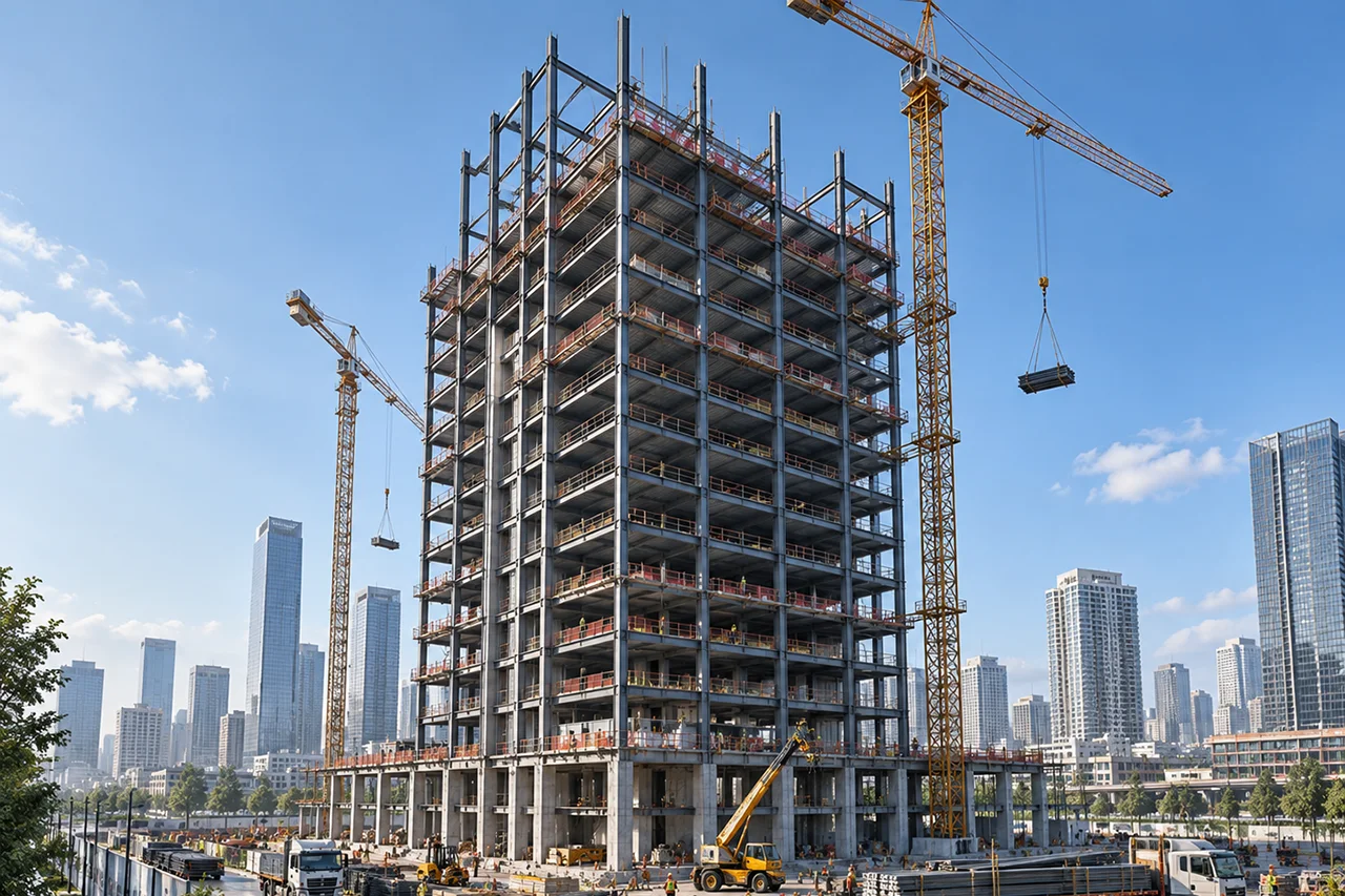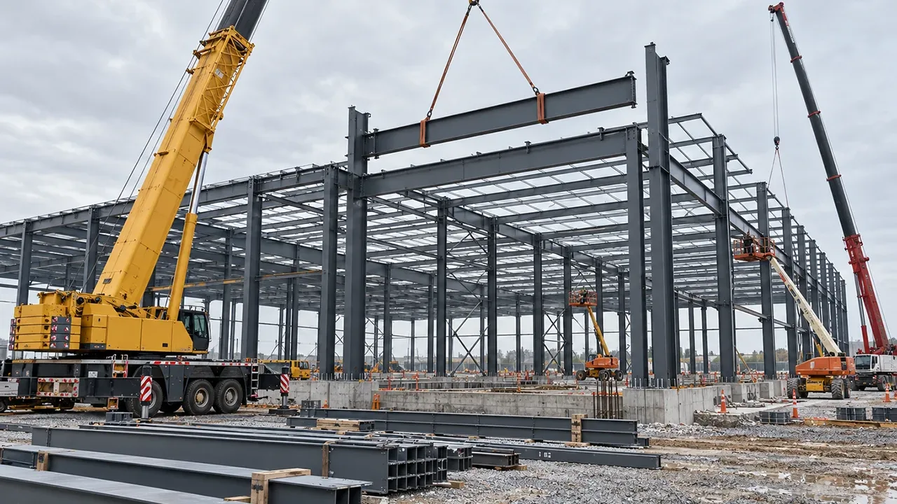
Steel structures are not supported only by beams carrying vertical loads. In many buildings, the most important forces move directly along the length of a member. These forces may act as compression, tension, or a combination of both depending on the structural system. Before selecting steel sections or designing connections, engineers must understand how axial loads move through columns, bracing, and truss members.
Axial load design is the process of checking whether a steel member can safely transfer force along its centerline without excessive deformation, buckling, yielding, or connection failure. It is especially important in industrial buildings, warehouses, factories, long-span roofs, and truss-supported structures where the load path must remain stable from the roof framing down to the foundation.
What Axial Load Design Means in Steel Structures
An axial force acts along the longitudinal axis of a member. When the force pushes the member together, it is called compression. When the force pulls the member apart, it is called tension. Many steel members are efficient because they can carry high axial force with relatively compact sections, but that efficiency depends on proper sizing, bracing, and connection detailing.
In a real steel structure, axial force rarely works in isolation. A column may carry compression while also resisting bending from wind or crane movement. A bracing member may carry tension under one load direction and compression under another. A truss member may be designed mainly for axial force, but poor joint alignment can introduce secondary bending. This is why axial load design must consider member strength, stability, geometry, and connection performance together.
Axial Compression
Compression occurs when the force pushes inward along the member. Steel columns, compression braces, and top chords of roof trusses commonly carry axial compression. The main design concern is not only whether the steel has enough material strength, but whether the member can remain stable under load. A long and slender compression member can buckle before the steel reaches its full yield strength.
Axial Tension
Tension occurs when the force pulls outward along the member. Bottom chords, tie members, cross bracing, and some diagonal truss members often carry axial tension. Tension members are usually less sensitive to buckling, but they still require careful checks for net section area, bolt holes, weld strength, gusset plates, and connection tear-out.
Main Steel Members That Carry Axial Forces
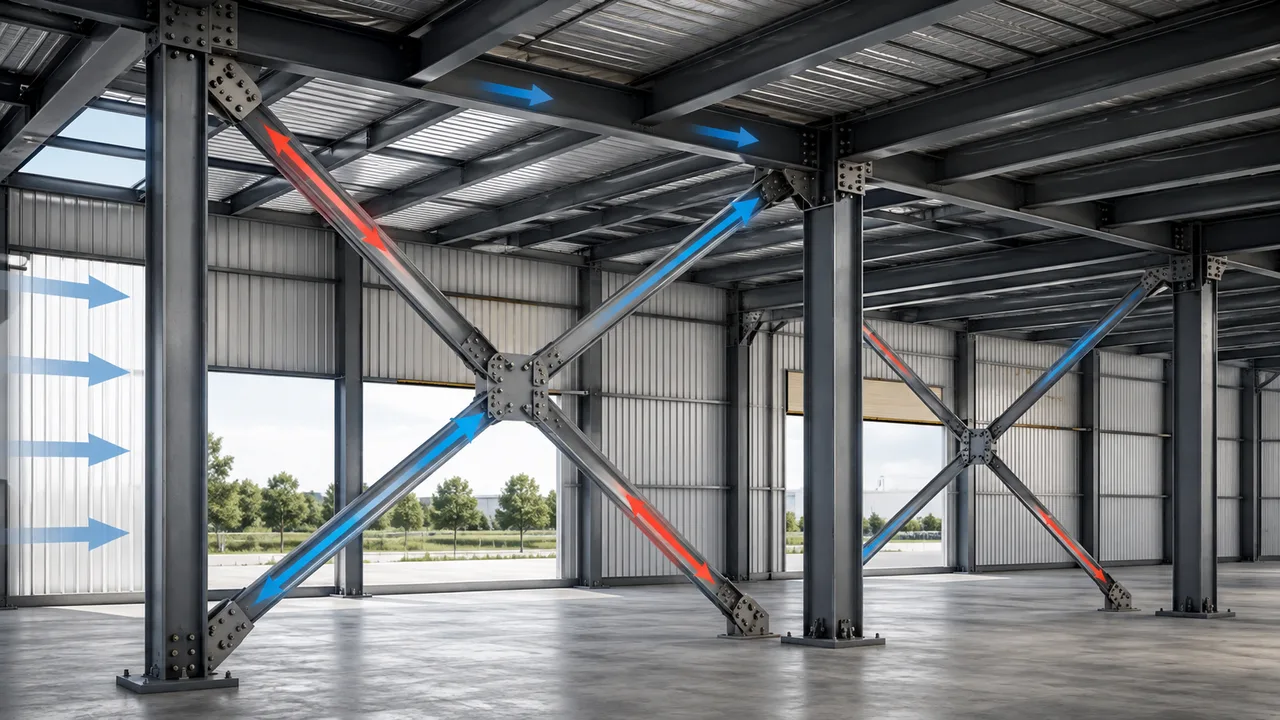
Axial force appears in many parts of a steel building, but columns, bracing systems, and truss members are usually the most important member groups to review. Each member type has a different role in the load path, so the design approach must match how the member works inside the structure.
Columns
Steel columns transfer vertical and lateral reactions from the upper structure to the foundation. In industrial buildings, columns may support roof framing, wall systems, mezzanine floors, crane brackets, pipe racks, or equipment platforms. Most columns are compression members, but they may also experience bending moments, shear forces, and uplift reactions depending on the frame system.
Bracing Members
Bracing members stabilize the building against lateral movement. They help transfer wind load, seismic load, equipment vibration, and frame sway into the foundation. Depending on the bracing arrangement, a brace may work in tension only, compression only, or both tension and compression.
Truss Members
Truss systems are designed to transfer load through a network of connected members. In an ideal truss, each member carries mainly axial tension or compression. This makes trusses highly efficient for long-span roofs, industrial halls, hangars, and large covered spaces where open interior space is required.
Axial Load Design for Steel Columns
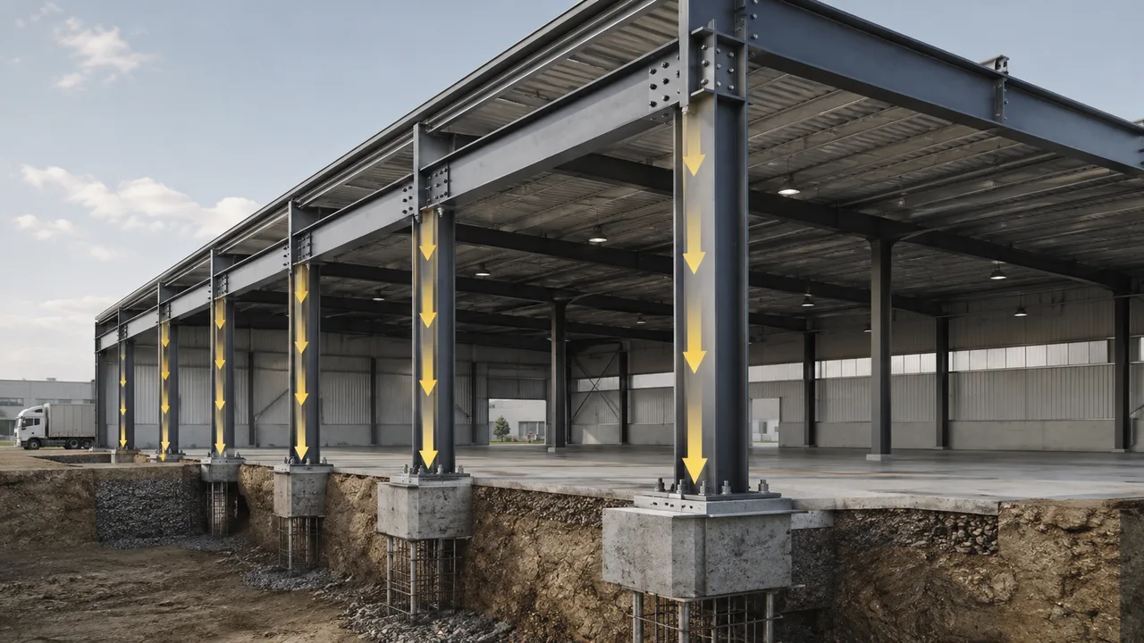
Column design usually begins with the vertical load demand from the roof, floor, equipment, cladding, and supported framing. The engineer then evaluates whether the selected steel section can resist the required compression while remaining stable in both major and minor axes. For slender columns, buckling often controls the design more than direct compression strength.
Unsupported length is one of the most important factors. A column that is restrained at intermediate points can carry more compression than a similar column with a longer unbraced length. The support condition at the base and top also affects the effective length. A fixed base, pinned base, rigid frame connection, or braced frame connection can all change how the column behaves.
Base plate design is another key part of the load path. Axial compression must transfer from the column into the base plate, anchor bolts, grout layer, and concrete foundation. If uplift is possible, the anchor bolts must also resist tensile force. For tall buildings or large industrial structures, column splices may be needed because of fabrication, transport, or installation limits. These splices must transfer axial force safely between column segments.
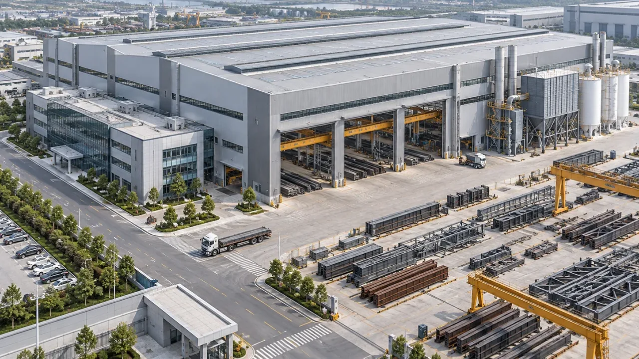
For warehouses, factories, and steel structure buildings, XTD Steel Structure coordinates column sizing, base detailing, fabrication tolerance, and installation requirements so the structural frame can transfer axial force safely from roof level to foundation level.
Axial Load Design for Bracing Members
Bracing is often the hidden stability system of a steel building. While beams and columns form the main frame, bracing members help control lateral movement and distribute horizontal forces. In roof planes, wall planes, and vertical bays, bracing provides a direct path for wind and seismic force to reach the foundation.
In tension-only bracing, the member is designed to work effectively when pulled. This is common in cross-bracing systems using rods, angles, or slender steel sections. Under the opposite load direction, the other diagonal may become active while the first brace relaxes. In tension-compression bracing, the brace must resist both pulling and pushing forces, so compression buckling must be checked carefully.
Connection design is especially important for bracing. The brace is commonly connected to columns and beams through gusset plates, bolts, and welds. If the gusset plate is too thin, poorly shaped, or misaligned with the brace centerline, the connection may introduce bending or local stress concentration. A brace may have enough member capacity, but the system can still fail if the connection cannot transfer the required force.
Axial Load Design for Truss Members
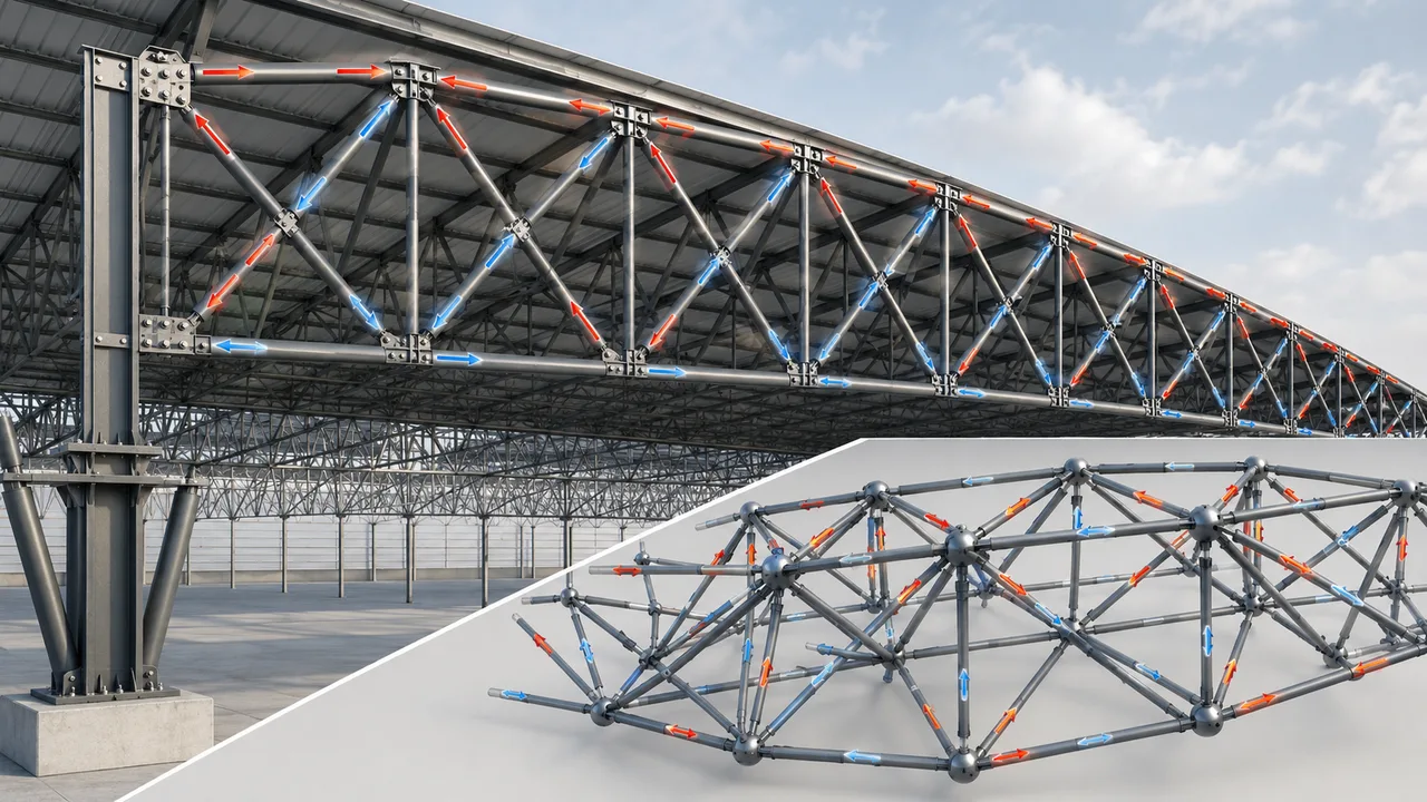
Trusses are among the clearest examples of axial force behavior in steel construction. A properly configured truss transfers roof loads through chords and web members, allowing long spans with efficient steel usage. Instead of relying on one deep beam, the truss divides the load into multiple members that carry tension and compression.
Top Chord Members
The top chord of a roof truss often carries compression under gravity loading. Because compression members are vulnerable to buckling, the top chord usually requires lateral restraint from purlins, roof bracing, or secondary framing. The spacing and stiffness of these restraints can strongly affect the member capacity.
Bottom Chord Members
The bottom chord often carries tension in a typical roof truss. Although tension members are generally efficient, the connection at each panel point must be designed to transfer the member force without tearing, excessive deformation, or bolt group failure. If the bottom chord also supports suspended loads, ceilings, service pipes, or maintenance platforms, those additional forces must be included.
Web Members
Diagonal and vertical web members may carry either tension or compression depending on the truss type and loading condition. In some cases, force reversal can occur under wind uplift or asymmetric loading. This means the engineer must evaluate whether a member that is normally in tension may also need compression capacity under another load case.
Panel Point Detailing
Good truss design depends on accurate panel point detailing. Ideally, the centerlines of connected members should meet at the joint. If the geometry is offset, the joint may create secondary bending that was not intended in the original member force calculation. This is one reason fabrication accuracy and shop drawing coordination are critical in truss construction.
How Axial Forces Work in a Space Truss
A space truss transfers load in three dimensions instead of one flat plane. It is often used for wide-span roofs, stadiums, terminals, exhibition halls, and large industrial buildings where the roof must cover a broad area without many interior columns. In a space truss, many short members connect at nodes, and each member is usually designed to carry axial tension or compression.
The advantage of this system is load distribution. Instead of concentrating force through a few large members, a space truss spreads force through a three-dimensional network. However, this also means node accuracy is very important. Each node must transfer forces from several directions, and fabrication tolerance must be controlled to avoid misalignment during assembly.
Key Checks in Axial Load Design
Axial load design requires more than selecting a steel profile from a table. The engineer must check the complete behavior of the member and its connection within the structural system.
Member Strength
The first check is whether the selected steel section has enough cross-sectional area and material strength to resist the required axial force. For tension members, this includes gross section and net section checks. For compression members, section strength must be reviewed together with stability.
Buckling Stability
Buckling is one of the most important concerns in compression design. A member with a small cross-section and long unsupported length can suddenly deflect sideways under compression. Buckling checks are essential for columns, compression braces, top chords, and compression web members.
Connection Capacity
Connections must be designed for the same force that the member carries. Bolts, welds, gusset plates, splice plates, base plates, and end plates all need enough capacity. If the member is strong but the connection is weak, the load path is still unsafe.
Fabrication and Installation Tolerance
Axial members are most efficient when the force passes cleanly through the member centerline. Fabrication errors, hole misalignment, plate distortion, or poor installation fit-up can create eccentricity. Even small eccentricity may introduce bending into a member that was intended to carry axial force only.
Erection-Stage Stability
A steel frame may not reach full stability until all bracing, purlins, columns, and connections are installed. Temporary supports or erection bracing may be required during construction. This is especially important for long-span trusses, tall columns, and partially assembled roof systems.
Comparison of Axial Load Members
| Member Type | Main Axial Force | Key Design Concern | Typical Connection Detail |
|---|---|---|---|
| Steel columns | Compression | Buckling, base reaction, and unsupported length | Base plate, anchor bolts, splice plates |
| Bracing members | Tension or compression | Lateral stability and gusset plate capacity | Gusset plates, bolts, welds |
| Truss top chord | Compression | Buckling and lateral restraint | Panel point connection |
| Truss bottom chord | Tension | Net section and joint force transfer | Bolted or welded chord connection |
| Truss web members | Tension or compression | Force reversal and member slenderness | Gusset plate or node connection |
Common Mistakes in Axial Load Design
One common mistake is treating every axial member as if it behaves the same way. A tension member and a compression member may look similar in the shop drawing, but their design checks are very different. Compression members need careful buckling review, while tension members often require close attention to net area and connection holes.
Another mistake is designing the member but underestimating the connection. In steel structures, the force must pass through the member, connection plate, bolt group, weld, supporting member, and foundation. A weak gusset plate, thin base plate, or poorly detailed splice can interrupt the load path.
Misalignment is also a major issue. If the brace or truss member does not align with the intended node, the connection may create eccentric force. This can cause local bending, plate distortion, and uneven bolt loading. For industrial buildings and long-span roofs, small detailing errors can become significant when member forces are high.
Why Connection Details Are Critical
Axial force does not stop at the end of a steel member. It must continue through the connection into the next part of the structure. This is why bolt shear, bolt bearing, weld length, plate thickness, edge distance, hole spacing, and gusset geometry must be checked carefully.
For columns, the connection may involve base plates, anchor bolts, stiffeners, and concrete foundations. For bracing, the connection may involve gusset plates and beam-column joints. For truss members, the connection may involve node plates, chord splice plates, or welded joint details. Each connection must match the force direction and member behavior.
A well-designed connection keeps the load path clear. It also helps reduce unexpected bending, local yielding, and installation problems. In fabricated steel structures, connection detailing is often where engineering design, workshop production, and site installation meet.
How XTD Steel Structure Supports Axial Load Design
For steel warehouses, factories, long-span roof systems, and industrial buildings, axial force behavior must be considered from early design through fabrication and installation. XTD Steel Structure supports this process through structural coordination, member fabrication, connection detailing, quality inspection, and project installation support.
This integrated approach helps ensure that columns, bracing members, truss components, and connection plates are not treated as isolated parts. Instead, they are coordinated as one complete steel structure system, allowing the final building to transfer loads safely and efficiently.
Practical Takeaway for Steel Structure Projects
Axial load design is one of the foundations of safe and efficient steel construction. Columns must resist compression and buckling. Bracing members must stabilize the building and transfer lateral force. Truss members must carry tension and compression through clear panel-point geometry. Connections must be strong enough to pass the force from one member to another without interrupting the load path.
For project owners, contractors, and engineers, understanding axial force behavior helps improve member selection, connection design, fabrication accuracy, and installation planning. Whether the structure is a factory, warehouse, roof truss, or long-span steel building, a reliable axial load path is essential for long-term performance.
FAQ About Axial Load Design
What Is Axial Load Design?
Axial load design is the process of checking whether a structural member can safely carry force along its length in tension or compression. It includes member strength, buckling stability, and connection capacity.
Which Steel Members Carry Axial Loads?
Steel columns, bracing members, truss chords, truss web members, tie members, and many space truss elements commonly carry axial forces in steel buildings.
Why Is Buckling Important in Compression Members?
Buckling is important because a compression member can lose stability before the steel reaches its full material strength. Slender columns, top chords, and compression braces must be checked carefully for buckling.
Do Connections Need to Be Designed for Axial Force?
Yes. Bolts, welds, gusset plates, base plates, splice plates, and node connections must be designed to transfer axial force safely from one member to another.