Shear loads in beam-to-column connections are a fundamental part of how forces move through a steel building. Floor slabs, roof systems, secondary framing, equipment, and other loads first act on beams before being transferred through their end connections into columns and eventually into the foundation. Although the beam reaction may appear straightforward in structural analysis, the actual connection must distribute that force through bolts, welds, plates, beam webs, column flanges, and column webs without creating an unintended weak point.
This means connection design cannot stop after checking the nominal shear strength of a few bolts or a weld line. Engineers must understand the complete load path, the behavior assumed in the structural model, local stresses around the joint, connection eccentricity, and possible interaction between shear, axial force, and bending moment.
The appropriate solution depends on beam reaction, connection geometry, framing system, member sizes, loading combinations, fabrication method, erection access, and the applicable structural design standard. A well-designed beam-to-column connection should transfer forces efficiently while remaining practical to fabricate, inspect, transport, and assemble on site.
What Are Shear Loads in Beam-to-Column Connections?
A shear load at a beam-to-column joint is commonly associated with the vertical reaction developed at the end of a beam. As loads act on the supported beam, internal shear forces develop and are transferred through the connection into the supporting column.
Typical sources include:
- Self-weight of structural steel
- Floor or roof dead loads
- Occupancy live loads
- Storage loads
- Mechanical and process equipment
- Roof rain or snow loads where applicable
- Wind-related frame actions
- Seismic forces
- Temporary construction loads
The beam reaction itself is only the beginning of the connection load path. After the force reaches the end of the beam, it must pass through connection plates, angles, bolts, welds, or other components before entering the supporting column.
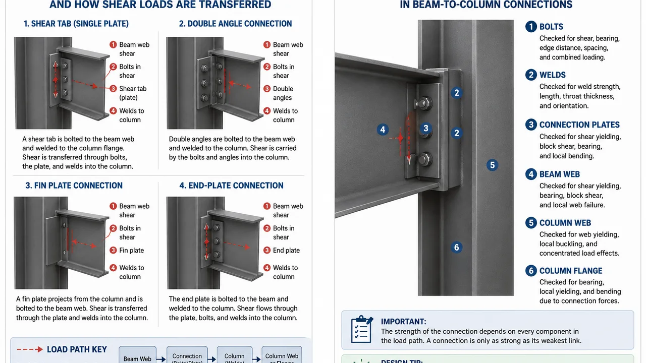
For example, in a simple shear-tab connection, the beam web transfers force into bolts, the bolts transfer it into the shear plate, and the plate transfers it through welds into the column. Every component along this path must have adequate strength and deformation capacity.
The structural model and physical detailing must also agree. A connection modeled as nominally pinned should provide sufficient rotational flexibility to behave consistently with that assumption. A joint intended to transfer significant bending moment requires a different connection arrangement and additional checks.
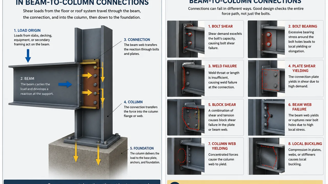
How Shear Loads Travel Through a Steel Frame
Understanding the complete force path helps prevent local connection failures and inconsistencies between structural analysis and fabrication details.
From the Floor or Roof System to the Beam
Loads may begin at concrete slabs, metal decking, roof panels, purlins, joists, secondary beams, or other supported systems. These elements distribute load to the primary beam.
A uniformly loaded beam typically develops reactions at its supports. Concentrated equipment loads, secondary framing reactions, or irregular loading can create additional forces that need to be considered individually.
From the Beam Into the Connection
At the beam end, the reaction must enter the connection through a defined structural mechanism.
Depending on the connection type, force transfer may occur through:
- Bolts through the beam web
- Welds between plates and supporting members
- Single shear plates
- Double angles
- End plates
- Seats
- Combined flange-and-web connection components
Connection geometry determines whether the force is transferred almost concentrically or creates additional eccentricity.
From the Connection Into the Column
Once the force passes through the connection components, it enters the column flange or column web.
This concentrated load can create local demands that are sometimes overlooked when attention is focused only on bolts and welds. Depending on joint geometry and force magnitude, engineers may need to evaluate column web yielding, local buckling, bearing, crippling, or other localized behavior.
From the Column to the Foundation
The column carries the accumulated reactions from connected beams downward through the structure. These forces eventually combine with other gravity and lateral actions before being transferred through column bases, base plates, anchor systems, and foundations.
This complete path illustrates why a connection should never be evaluated as an isolated component.
Common Beam-to-Column Connections That Transfer Shear
Different connection types can transfer beam reactions efficiently, but their structural behavior, fabrication requirements, and installation characteristics vary.
| Connection Type | Typical Force Transfer | Rotation Behavior | Common Application |
|---|---|---|---|
| Single shear plate | Beam web bolts to a welded plate | Relatively flexible | Simple framing |
| Double-angle connection | Angles connect beam web to supporting member | Relatively flexible | Conventional beam framing |
| Fin plate connection | Beam web transfers reaction through a projecting plate | Generally designed for simple behavior | Industrial and building frames |
| End-plate connection | Beam reaction transfers through plate, bolts, and welds | Depends on detailing | Simple or moment-resisting framing |
| Seated connection | Beam reaction bears onto a supporting seat | Can permit beam-end rotation | Higher reactions or erection convenience |
| Moment connection | Web and flange components transfer shear and moment | Restricted rotation | Moment-resisting frames |
Connection selection should not be based only on which detail is easiest to draw. Beam reaction, member geometry, required rotational behavior, field access, fabrication strategy, and overall structural system should influence the choice.
Shear Loads in Simple Connections vs Moment Connections
The behavior of shear loads in beam-to-column connections changes significantly depending on whether the joint is intended to act primarily as a simple connection or as part of a moment-resisting frame.
Simple Shear Connections
A simple connection is generally intended to transfer the beam-end shear reaction while allowing enough rotational flexibility for the beam to behave approximately as assumed in a simply supported analysis.
Common examples include shear tabs, fin plates, double-angle connections, and some seated arrangements.
These connections should not be excessively rigid if the structural analysis assumes free or nearly free beam-end rotation. Unintended rotational restraint may alter moment distribution within the frame.
Moment-Resisting Connections
Moment connections transfer significant bending moment in addition to vertical shear. The force path therefore becomes more complex.
Beam flanges commonly participate in transferring bending actions, while the web region may transfer much of the shear. End plates, flange plates, bolts, welds, continuity plates, and column panel-zone components can all contribute to joint behavior.
Because several actions occur simultaneously, engineers must consider combined loading rather than checking shear independently.
Why Connection Behavior Matters
Two beams carrying similar vertical reactions can require very different connections if one joint is modeled as simple and the other belongs to a moment-resisting frame.
Structural analysis assumptions, connection stiffness, and fabricated details must therefore remain compatible throughout design and construction.
Key Components Checked for Shear Capacity
The capacity of a connection depends on multiple possible limit states. Checking only one component can leave another part of the force path vulnerable.
Bolts
Bolted connections may require checks for:
- Bolt shear
- Bearing around bolt holes
- Edge distance
- Bolt spacing
- Slip where relevant to the connection type
- Combined loading
- Bolt-group behavior under eccentric force
Increasing the number of bolts does not automatically solve every problem because the surrounding plate and beam web must also resist the corresponding forces.
Welds
Weld design can depend on:
- Weld throat thickness
- Effective weld length
- Weld orientation
- Base-metal strength
- Load direction
- Eccentricity
- Fabrication and inspection access
A weld may have sufficient nominal strength but still be difficult to produce reliably if the connection geometry creates restricted access.
Connection Plates
Shear tabs, end plates, angles, and other connection components must be checked for relevant failure modes such as:
- Shear yielding
- Shear rupture
- Block shear
- Bearing at bolt holes
- Local bending
- Net-section effects
Plate thickness should therefore be selected from structural requirements rather than only fabrication convenience.
Beam Web
The beam web is directly involved in many shear connections.
Potential concerns include:
- Shear yielding
- Rupture near bolt holes
- Bearing deformation
- Block shear
- Local web deformation
- Interaction with concentrated forces
The connection should introduce the reaction into the beam web in a manner consistent with its actual capacity.
Column Web and Flange
The supporting column must also be capable of receiving the connection forces.
Large concentrated reactions may require evaluation of the column flange, web, panel zone, and nearby stiffened regions. In some conditions, local reinforcement may be necessary to distribute the load safely.
Shear Loads and Connection Eccentricity
Connection forces do not always act directly through the centroid of the resisting bolt group, weld group, or plate.
When the line of action is offset, the shear force creates an additional moment. This effect is known as connection eccentricity.
Examples include:
- Single plates projecting from a column flange
- One-sided angle connections
- Brackets supporting beams away from a column centerline
- Offset framing conditions
- Connections involving unusual architectural geometry
Ignoring eccentricity can underestimate demand on bolts, welds, plates, and supporting members.
For this reason, the geometry of the actual fabricated connection should be used when evaluating the force transfer mechanism rather than assuming that every beam reaction acts concentrically.
Interaction Between Shear and Moment
Real steel connections often carry more than one type of force.
Vertical shear may occur together with:
- Bending moment
- Axial tension
- Axial compression
- Torsion
- Lateral frame forces
Even a connection categorized as a shear connection can develop secondary moments because of eccentricity, connection stiffness, deformation compatibility, or unusual loading.
Moment-resisting connections require even greater attention because shear and bending are intentionally transferred through the joint.
For a broader explanation of how these forces are established and checked throughout steel members and framing systems, see shear load design.
The key principle is that connection components should be evaluated under the combinations of forces they actually experience rather than under isolated idealized actions.
Shear Loads Under Lateral Frame Actions
Gravity loading is not the only source of shear demand in steel frames. Wind and seismic actions can modify force distribution and may even reverse forces in some connection components.
Wind Loads
Wind acting on walls and roofs enters the structural frame through cladding supports, diaphragms, bracing systems, and moment frames.
Beam-to-column joints may therefore experience additional forces depending on their role in the lateral-force-resisting system.
Wind uplift can also reverse reactions in roof framing compared with ordinary downward gravity loading.
Seismic Loads
Seismic loading can create cyclic forces and repeated load reversals. Connections used in seismic-force-resisting systems may require substantially different detailing from ordinary gravity connections.
Strength alone may not be sufficient. Ductility, deformation capacity, connection hierarchy, member stability, and expected inelastic behavior may become important design considerations.
Braced Frames
In braced frames, brace forces can introduce significant local demands close to beam-to-column joints.
Gusset plates, beam ends, column webs, and supporting connections may interact within a relatively compact region. The engineer should evaluate the complete joint rather than considering the beam reaction independently from the brace connection.
When Stiffeners Are Needed Near Beam-to-Column Connections
Stiffeners can help distribute concentrated forces or prevent local instability, but they should not be added automatically to every heavily loaded connection.
They may become necessary where there are:
- High beam reactions
- Thin column webs
- Large concentrated forces
- Local web yielding concerns
- Web crippling risk
- Local buckling concerns
- Closely spaced connections
- Combined moment and shear demands
A stiffener changes how forces travel through the joint. Its welds, fit-up, geometry, and access must therefore also be designed.
From a fabrication perspective, excessive stiffening can increase cutting, welding, inspection, coating difficulty, and distortion. A more efficient solution may sometimes involve selecting a stronger supporting member rather than adding numerous local reinforcement plates.
Typical Failure Modes Related to Connection Shear
Several possible limit states should be considered when evaluating the complete connection.
| Failure Mode | Typical Location | Main Concern | Possible Design Response |
|---|---|---|---|
| Bolt shear | Bolted connection | Shear demand exceeds bolt resistance | Revise bolt size, grade, or quantity |
| Bolt bearing | Beam web or plate | Excessive bearing around holes | Revise thickness, spacing, or edge distance |
| Weld failure | Plate-to-column or beam-to-plate interface | Insufficient weld resistance | Revise weld size, length, or configuration |
| Plate shear yielding | Shear plate or end plate | Plate stress exceeds allowable resistance | Increase thickness or revise geometry |
| Block shear | Plate or beam web near bolts | Combined tension-and-shear failure path | Revise bolt layout or material area |
| Beam web failure | Beam end | High local reaction or reduced net section | Reinforce or modify connection detail |
| Column web yielding | Supporting column | Concentrated connection force | Use reinforcement or revise member selection |
| Local buckling | Web, plate, or stiffened region | Compression instability | Reduce slenderness or provide reinforcement |
Good connection design checks the entire sequence of possible limit states and avoids creating a situation in which one strengthened component simply transfers excessive demand into another weaker component.
Shear Load Design Workflow for Beam-to-Column Connections
A practical connection design process can follow a systematic sequence:
- Define the structural framing system and expected connection behavior.
- Determine beam-end reactions from the structural analysis.
- Identify the governing load combinations.
- Establish the complete connection load path.
- Select an appropriate connection type.
- Check bolt or weld resistance.
- Check connection plates, angles, or end plates.
- Evaluate the beam web and surrounding beam material.
- Check the supporting column flange and web.
- Evaluate eccentricity and secondary moments.
- Check interaction with axial force or bending where relevant.
- Add reinforcement only where structural checks require it.
- Review fabrication access and installation tolerances.
- Confirm that erection sequencing does not create temporary instability.
This workflow prevents the design from becoming a simple bolt-capacity calculation and helps ensure that all components along the force path are compatible.
Fabrication and Detailing Considerations
A structurally efficient connection should also be practical to manufacture.
Important detailing considerations include:
- Access for tightening bolts
- Welding position and accessibility
- Plate thickness and cutting requirements
- Bolt-hole tolerances
- Clearance between adjacent connection components
- Access for coating and corrosion protection
- Shop welding versus field welding
- Inspection requirements
- Stiffener congestion
- Repeatability across similar framing bays
For repetitive steel buildings, standardizing similar beam-to-column details can significantly improve fabrication efficiency. Repeated plate dimensions, bolt patterns, and weld configurations can reduce production variation and simplify inspection.
However, standardization should not override structural requirements. Connections with substantially different reactions may require different plate sizes, bolt arrangements, or reinforcement.
For manufacturers such as XTD Steel Structure, connection detailing is closely connected to CNC processing, shop welding, trial assembly where required, component identification, surface treatment, packaging, and erection planning. The fabrication model should therefore accurately reflect the intended structural load path.
Installation and Erection Considerations
Connections must also remain safe during construction before the complete steel frame becomes stable.
During erection:
- Beams may temporarily carry loads different from final design conditions.
- Permanent bracing may not yet be installed.
- Connections may initially contain only erection bolts.
- Columns may have limited lateral restraint.
- Temporary platforms or lifting equipment may introduce additional forces.
The erection sequence should specify when connections achieve their required structural condition.
Misaligned members should not simply be forced into position if doing so introduces unintended stresses or damages connection plates. Field cutting, drilling, or welding can alter the structural capacity and should be reviewed before modification.
Temporary stability is particularly important in long bays, tall frames, and structures with significant lateral loads.
Common Design Mistakes
Several recurring mistakes can reduce the reliability or economy of beam-to-column connections.
Checking Only the Bolts
A bolt group may have sufficient resistance while the connected plate, beam web, weld, or column web remains inadequate. The entire load path must be evaluated.
Ignoring Eccentricity
An offset between the load and connection resistance creates additional moment that can increase bolt and weld forces.
Treating Every Joint as a Pure Shear Connection
Actual connection stiffness, framing geometry, axial actions, lateral loads, or moment transfer may produce forces beyond simple vertical shear.
Adding Suspended Loads After Fabrication
New ductwork, piping, platforms, conveyors, or mechanical equipment can increase beam reactions and connection demands beyond the original design assumptions.
Ignoring the Supporting Column
A strong beam connection can still create local yielding or instability in a thin column web or flange.
Overusing Stiffeners
Reinforcement that is not structurally necessary increases material, welding, inspection, and fabrication complexity.
Comparing Connections Only by Steel Weight
A lighter plate arrangement may require additional bolts, longer welds, difficult fit-up, or more field labor. Total fabricated and installed cost is often more important than connection weight alone.
Choosing the Right Connection for the Required Shear Load
The best connection depends on the complete project rather than a single force value.
Selection factors commonly include:
- Magnitude of the beam reaction
- Beam depth and web thickness
- Column orientation and section size
- Required rotational behavior
- Whether moment transfer is required
- Connection eccentricity
- Available bolt access
- Shop and field welding strategy
- Number of repeated connections
- Seismic or wind requirements
- Transportation limitations
- Erection sequence
- Inspection requirements
- Total fabrication and installation cost
Standard connection details are useful starting points, but they should not replace engineering evaluation. A detail that performs efficiently in one building may be inappropriate when reactions, section geometry, lateral-force requirements, or installation conditions change.
Shear Loads in Beam-to-Column Connections: Final Design Considerations
Shear loads in beam-to-column connections should be evaluated as part of the complete structural force-transfer system rather than as isolated beam reactions.
The load begins in the floor, roof, equipment, or secondary framing, travels through the beam, crosses the connection, enters the column, and continues toward the foundation. Along that path, bolts, welds, connection plates, beam webs, column flanges, column webs, stiffeners, and surrounding structural components may all influence performance.
Simple shear connections and moment-resisting connections also require different assumptions regarding rotation and force transfer. Eccentricity, combined loading, local failure modes, construction tolerances, and temporary erection conditions can further change connection demand.
A successful design therefore combines structural analysis with practical detailing, fabrication, inspection, and installation planning. When every part of the load path is considered together, beam-to-column connections can transfer shear efficiently while supporting safe, economical, and constructible steel frames.